Circutor CEM-C12 Multifunctional Energy Meter
SAFETY PRECAUTIONS
Follow the warnings described in this manual with the symbols shown below.
DANGER
Warns of a risk, which could result in personal injury or material damage.
ATTENTION
Indicates that special attention should be paid to a specific point.
If you must handle the unit for its installation, start-up or maintenance, the following should be taken into consideration:
Incorrect handling or installation of the unit may result in injury to personnel as well as damage to the unit. In particular, handling with voltages applied may result in electric shock, which may cause death or serious injury to personnel. Defective installation or maintenance may also lead to the risk of fire.
Read the manual carefully prior to connecting the unit. Follow all installation and maintenance in-structions throughout the unit’s working life. Pay special attention to the installation standards of the National Electrical Code.
Refer to the instruction manual before using the unit
In this manual, if the instructions marked with this symbol are not respected or carried out correctly, it can result in injury or damage to the unit and /or installations.
CIRCUTOR, SA reserves the right to modify features or the product manual without prior notification.
DISCLAIMER
CIRCUTOR, SA reserves the right to make modifications to the device or the unit specifications set out in this instruction manual without prior notice.
CIRCUTOR, SA on its web site, supplies its customers with the latest versions of the device specifications and the most updated manuals.

CIRCUTOR, recommends using the original cables and accessories that are supplied with the device.
REVISION LOG
Table 1: Revision log
| Date | Revision | Description |
| 03/22 | M336B01-03-21A | Initial Version |
SYMBOLS
| Symbol | Description |
| CE | In compliance with the relevant European directive. |
 | Device covered by European directive 2012/19/EC. At the end of its useful life, do not leave the unit in a household waste container. Follow local regulations on electronic equipment recycling. |
| ~ | AC current |
VERIFICATION UPON RECEPTION
Check the following points upon receiving the device:
- The device meets the specifications described in your order.
- The device has not suffered any damage during transport.
- Perform an external visual inspection of the device prior to switching it on.
- Check that it has been delivered with the following:
– An installation guide,
If any problem is noticed upon reception, immediately contact the transport com-pany and/or CIRCUTOR’s after-sales service.
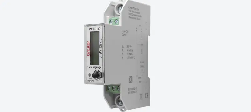
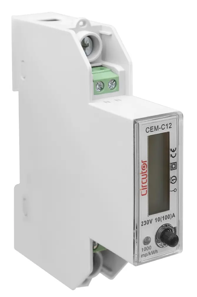
PRODUCT DESCRIPTION
The CEM-C12 static single-phase energy meter measures class 1 (IEC 62053-21) / class B (EN50470), with multifunction, RS-485 communications and DIN rail standard installations. It is the ideal solution for residential and commercial installations.
The device features:
- Only 18 mm wide, can up to 100A.
- RS-485 communication, protocol: IEC1107 or Modbus-TRU Mode.
- Device has 3.6V Lithium battery. The precision of RTC is better that 0.5s/day.
- Blue LCD backlight allows the device to be read in low light conditions.
- 1 key, to move between the different display screens and be able to configure the communications.
DEVICE INSTALLATION
PRELIMINARY RECOMMENDATIONS
In order to use the device safely, it is critical that individuals who handle it follow the safety measures set out in the standards of the country where it is being used, use the necessary personal protective equipment, and pay attention to the various warnings indicated in this instruction manual.
The CEM-C12 device must be installed by authorised and qualified staff.
The measuring systems switched off before handling, altering the connections or replacing the device. It is dangerous to handle the unit while it is powered.
Also, it is critical to keep the cables in perfect condition in order to avoid accidents, personal injury and damage to installations.
The manufacturer of the device is not responsible for any damage resulting from failure by the user or installer to observe the warnings and/or recommendations set out in this manual, nor for damage resulting from the use of non-original products or accessories or those made by other manufacturers.
If an anomaly or malfunction is detected in the device, do not use the device to take any measurements.
Inspect the work area before taking any measurements. Do not take measurements in dangerous areas or where there is a risk of explosion.
Disconnect the device from the power supply before maintaining, repairing or handling the device’s connections.
Please contact the after-sales service if you suspect that there is an operational fault in the device.
INSTALLATION
Terminals, opening covers or removing elements can expose parts that are hazardous to the touch while the device is powered. Do not use the device until it is fully installed.
Installation instruction:
- Choose 35mm standard DIN rail (the length is confirmed by yourself), fixed them in the location which are waiting for installation.
- Push down the clip under the bottom of the meter for a gear, see Figure 1
 Figure 1:Push down the clip
 - Put the meter into the DIN rail as per Figure 2, then push up the clip for a gear, install meter to the DIN rail, see Figure 3.
 Figure 2:Put the meter into the DIN rail
 Figure 3: Install meter to the DIN rail
 - Making the connection according to the wiring diagram.
- After connection, use lead sealing to seal terminal cover.
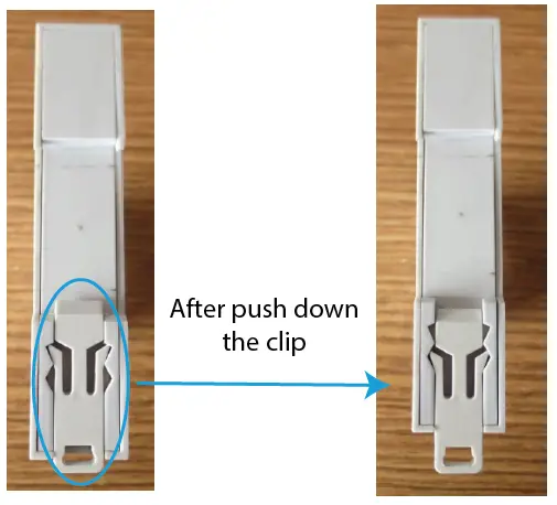 Figure 1:Push down the clip
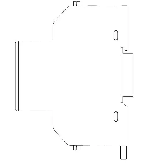 Figure 2:Put the meter into the DIN rail
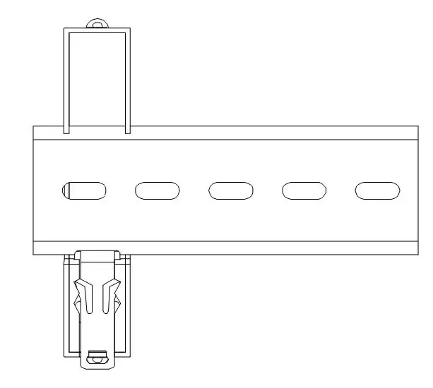 Figure 3: Install meter to the DIN rail
DEVICE TERMINALS
Table 3:List of CEM-C12 terminals
| Device terminals | |
| 1 : L, Input, connected to the mains phase | B-: B-, RS-485 connection |
| 3: LOAD, Output | S: S, RS-485 connection |
| N: N, Input, connected to neutral | A+: A+, RS-485 connection |
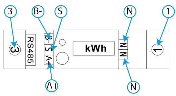 Figure 4:Terminals of the CEM-C12
Note: The Neutral wire can be connected to one of N ports or both.
Note: If RS-485 installation does not have S port, it is not necessary to connect it.
CONNECTION DIAGRAM
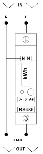 Figure 5: Connection diagram, CEM-C12
OPERATION
The CEM-C12 measures in the 4 quadrants (consumption and generation).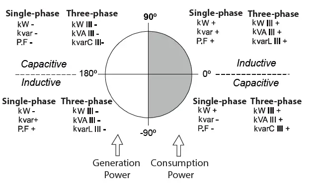 Figure 6: Sign convention
Table 4: CEM-C12 Measurement parameters
| Parameter | Display | RS-485 | ||
| Instantaneous | Maximum | Minimum | ||
| Voltage | ü | ü | ü | ü |
| Current | ü | ü | ü | ü |
| Frequency | ü | ü | – | – |
| Active Power | ü | ü | ü | ü |
| Reactive Power | ü | ü | ü | ü |
| Inductive Reactive Power | – | ü | ü | ü |
| Capacitive Reactive Power | – | ü | ü | ü |
| Apparent Power | ü | ü | ü | ü |
| Power Factor | ü | ü | ü | ü |
| Maximum Active Power Demand | – | ü | ü | – |
| Active Energy Consumed | – | ü | – | – |
| Active Energy Generated | – | ü | – | – |
| Total Active Energy | ü | ü | – | – |
| Inductive Reactive Energy Consumed | ü | ü | – | – |
| Inductive Reactive Energy Generated | – | ü | – | – |
| Capacitive Reactive Energy Consumed | – | ü | – | – |
| Capacitive Reactive Energy Generated | – | ü | – | – |
| Reactive Energy Consumed | – | ü | – | – |
| Reactive Energy Generated | – | ü | – | – |
| Total Reactive Energy | – | ü | – | – |
Maximum demand
The maximum demand is the average instantaneous power over a specific time interval, usually 15 minutes. There are several ways to calculate this parameter:
Fixed Window (by block)
This is the calculation of maximum demand in a specific interval (usually every 15 minutes). Once the number is calculated, the value is saved and a new calculation for the next 15 minutes begins. The result would be 4 values per hour.
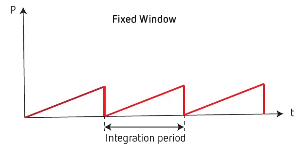 Figure 7: Fixed Window.
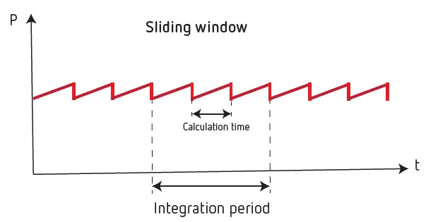
Figure 8: Sliding Window.
The CEM-C12 calculates the Maximum demand with a fixed window and a 15-minute integration period
KEYBOARD FUNCTIONS
The CEM-C12 has one key to move around the different screens and configure the communications (Figure 9).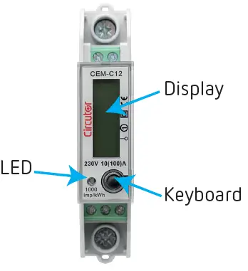 Figure 9: CEM-C12, description
DISPLAY
The device has an LCD where all parameters are displayed (Figure 9).
LED INDICATORS
The device has one verification LED, to verify the active energy The weight of the LED is 1000 imp/kWh (Figure 9).
DISPLAY
The data can be displayed through 2 methods:
- Automatically, the device automatically switches screens every 5 seconds.
- Pressing the key.
| Screen | Parameters |
| 123450 KWH | Total Active Energy (consumed + generated) (kWh) |
| 1200 kVArh | Inductive Reactive Energy consumed (kVArh) |
| 2300V | Voltage (V) |
| 005.0A | Current (A) |
| F 50.00 | Frequency (Hz) |
| PF 1.00 | Power factor (cos Φ) |
| 11.50 kW | Active power (kW) |
| 00.00kVAr | Reactive power (kVAr) |
| 115.0 kVA | Apparent power (kVA) |
CONFIGURING RS-485 COMMUNICATIONS
To go into the communications configuration menu, press > 5 seconds while in any display screen.
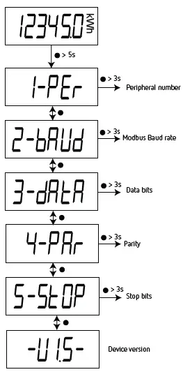 Figure 10: Communications menu
If the key is not pressed for 10 seconds, the device skips to the display screens.
PERIPHERAL NUMBER
This screen enables peripheral number configuration. To go into the configuration screen, press > 3 seconds.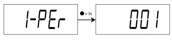 Press to change the digit value.
Press > 3 seconds to change digits.
Press > 6 seconds to save the change. The screen shown in Figure 11 indicates that the changes have been saved correctly.
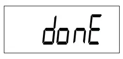
Figure 11:Done screen
Configuration values
Table 6: Configuration values: Peripheral nº
| Peripheral Nº | |
| Minimum value | 1 |
| Maximum value | 247 |
Press to skip to the next programming step.
MODBUS BAUD RATE
This screen is used to configure the Baud Rate. Press > 3 seconds to open the configuration screen.
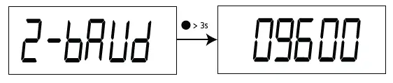
Press to change options.
Press > 6 seconds to save the change. The screen shown in Figure 11 indicates that the changes have been saved correctly.
Configuration values
Table 7:Configuration values: Baud rate
| Baud Rate | ||
| Possible values | 9600 | 9600 bps |
| 19200 | 19200 bps | |
| 38400 | 38400 bps | |
Press to skip to the next programming step.
DATA BITS
This screen shows the number of data bits. Press > 3 seconds to open the configuration screen.
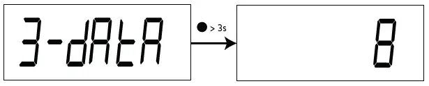
Note: This parameter cannot be modified.
Press to skip to the next programming step.
PARITY
This screen is used to configure the parity. Press > 3 seconds to open the configuration screen.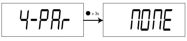 Press to change options.
Press > 6 seconds to save the change. The screen shown in Figure 11 indicates that the changes have been saved correctly.
Configuration values
Table 8: Configuration values: Parity
| Parity | ||
| Possible values | MOME | No parity |
| Odd | Odd parity | |
| EUEM | Even parity | |
Press to skip to the next programming step.
STOP BITS
This screen is used to configure the number of stop bits. Press > 3 seconds to open the configuration screen.
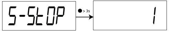 Press to change options.
Press > 6 seconds to save the change. The screen shown in Figure 11 indicates that the changes have been saved correctly.
Configuration values
Table 9: Configuration values: Stop bits
| Stop bits | ||
| Possible values | 1 | 1 stop bit |
| 2 | 2 stop bit | |
Press to skip to the next programming step.
RS-485 COMMUNICATIONS
The CEM-C12 has one RS-485 communications port to view the measurement data and configure the devices. The visualization and configuration can also be done through the CIRCUTOR PowerStudio software.
Note: Default values of RS-485 communication: No. of peripheral 1, 9600 bps, No parity, 8 data bits and 1 stop bit.
MODBUS PROTOCOL
In the Modbus protocol, the CEM-C12 device uses the RTU (Remote Terminal Unit) mode.
The Modbus functions implemented in the device are as follows:
Function 0x03: Reading integer registers
Function 0x10: Writing multiple registers
READING EXAMPLE:
Function 0x03
Question: Voltage value
| Address | Function | Initial register | No of registers | CRC |
| 01 | 03 | 0000 | 0002 | C40B |
Address: 01, Peripheral number: 1 in decimals.
Function: 03, Read function.
Initial Register: 0000, register on which the reading will start. (Modbus address).
No of registers: 0002, number of registers read.
CRC: C40B, CRC Character.
Response:
| Address | Function | No of Bytes | Register no 1 | Register no 2 | CRC |
| 01 | 03 | 02 | 0000 | 091F | 359A |
Address: 01, Responding peripheral number: 10 in decimals.
Function: 03, Read function.
No of bytes: 02, No. of bytes received.
Register: 091F, value of the voltage :0000091F : 2335 → 233.5V CRC: 359A, CRC Character.
WRITING EXAMPLE: Function 0x10.
Question: Modify the Modbus baud rate to 9600 bps
| Address | Function | Initial Register | No of Registers | No of Bytes | Value | CRC |
| 01 | 10 | 0064 | 0001 | 02 | 0004 | xxxx |
Address: 01, Peripheral number: 1 in decimals.
Function: 10, Writing function.
Initial Register: 0064, Address of the Baud rate parameter. No of registers: 0001, number of registers write.
No of bytes: 02, number of bytes write.
Value: 0004, 0004 → 9600 bps.
CRC: xxxx, CRC Character.
MODBUS COMMANDS
Note: The waiting time of a Modbus query can exceed 200 ms, depending on the number of registers requested.
All the addresses of Modbus memory are in Hexadecimal.
Table 10: Modbus memory map (Table 1)
| Parameter | Function | Modbus address | Units | ||
| Instantaneous | Maximum | Minimum | |||
| Voltage | 03 | 00 – 01 | 32 – 33 | 44 – 45 | V x 10 |
| Current | 03 | 02 – 03 | 34 – 35 | 46 – 47 | A x 100 |
| Active Power | 03 | 04 -05 | 36 – 37 | 48 – 49 | kW x 100 |
| Reactive Power | 03 | 06 – 07 | 38 – 39 | 4A – 4B | kvar x 100 |
| Inductive Reactive Power | 03 | 08 – 09 | 3A – 3B | 4C – 4D | kvarL x 100 |
| Capacitive Reactive Power | 03 | 0A – 0B | 3C – 3D | 4E – 4F | kvarC x 100 |
| Apparent Power | 03 | 0C – 0D | 3E – 3F | 50 – 51 | kVA x 100 |
| Power Factor | 03 | 0E – 0F | 40 – 41 | 52 – 53 | x 100 |
| Maximum demand of the Active Power | 03 | 10 – 11 | 42 – 43 | – | kW x 100 |
Table 11: Modbus memory map (Table 2)
| Parameter | Function | Modbus address | Units |
| Consumed Active Energy Total | 03 | 12 – 13 | kWh x 100 |
| Consumed Inductive Reactive Energy Total | 03 | 14 – 15 | kvarh x 100 |
| Consumed Capacitive Reactive Energy Total | 03 | 16 – 17 | kvarh x 100 |
| Consumed Reactive Energy Total | 03 | 18 -19 | kvarh x 100 |
| Consumed Active Energy Partial | 03 | 1A – 1B | kWh x 100 |
| Consumed Inductive Reactive Energy Partial | 03 | 1C – 1D | kvarh x 100 |
| Consumed Capacitive Reactive Energy Partial | 03 | 1E – 1F | kvarh x 100 |
| Consumed Reactive Energy Parcial | 03 | 20 – 21 | kvarh x 100 |
| Generated Active Energy Total | 03 | 22 – 23 | kWh x 100 |
| Generated Inductive Reactive Energy Total | 03 | 24 – 25 | kvarh x 100 |
| Generated Capacitive Reactive Energy Total | 03 | 26 – 27 | kvarh x 100 |
| Generated Reactive Energy Total | 03 | 28 – 29 | kvarh x 100 |
| Generated Active Energy Partial | 03 | 2A – 2B | kWh x 100 |
| Generated Inductive Reactive Energy Partial | 03 | 2C – 2D | kvarh x 100 |
| Generated Capacitive Reactive Energy Partial | 03 | 2E – 2F | kvarh x 100 |
| Generated Reactive Energy Partial | 03 | 30 – 31 | kvarh x 100 |
| Frequency | 03 | 5A | Hz x 100 |
| Parameter | Function | Modbus address | Units |
| Total active Energy (Consumed + Generated) | 03 | 5B – 5C | kWh x 100 |
| Total reactive energy (Consumed + Generated) | 03 | 5D – 5E | kvarh x 100 |
Table 12: Modbus memory map (Table 3)
| Parameter | Function | Modbus address |
| Reset of maximum values | 05 | 5F |
| Reset of minimum values | 05 | 60 |
| Maximum Demand Reset | 05 | 61 |
| Reset of Partial Energies | 05 | 62 |
| Total reset (Maximum and minimum values, Maximum demand and Partial Energies) | 05 | 63 |
Table 13: Modbus memory map (Table 4)
| Parameter | Modbus address | Function | Data format |
| Date and time | 56 … 59 | 03 / 10 | YY YY MM DD WW hh mm ss (1) |
| Serial number | 69 … 6C | 04 | – |
(1)Data format :
Table 14: Data format
| Parameter | Data format | Description |
|
Date and time | YY YY (decimal value) | Year |
| MM (decimal value) | Month | |
| DD (decimal value) | Day | |
| WW (decimal value) | Weekday number | |
| hh (decimal value) | Hour | |
| mm (decimal value) | Minutes | |
| ss (decimal value) | Seconds |
Table 15: Modbus memory map (Table 5)
| Parameter | Modbus address | Function | Default values | Data format |
| Baud Rate | 64 | 04 / 10 | 04 | 04: 9600 bps| 05: 19200 bps, 06: 38400 bps |
| ID (peripheral number) | 65 | 04 / 10 | 1 | 1 – 247 |
| Parity | 66 | 04 / 10 | 0 | 0: none, 1: odd, 2: even |
| Data bits | 67 | 04 | 0 | 0: 8 bits |
| Stop bits | 68 | 04 / 10 | 0 | 0: 1 stop bit, 1: 2 stop bit |
TECHNICAL FEATURES
| Power supply | |
| Mode | Self-powered |
| Voltage Measurement | ||
| Connection | Single-phase | |
| Reference voltages | 230 V ~ | |
| Frequency | CEM-C12 | 50 / 60 Hz |
| CEM-C12-MID | 50 Hz | |
| Power consumption | ≤ 10 VA, ≤ 0.4 Wh | |
| Current measurement | |
| Current | 0.25 … 5 A |
| Maximum current (Imax) | 100 A |
| Starting current | 0.004 Ib |
| Accuracy | ||
| Accuracy | CEM-C12 | Class 1 (IEC 62053-21) |
| CEM-C12-MID | Class B (EN50470) | |
| RS-485 Communications | |
| Bus | RS-485 |
| Protocol | Modbus RTU |
| Baud rate | 9600 – 19200 – 38400 |
| User interface | |
| Display | LCD |
| Maximum counter value | 99999.9 kWh |
| Keys | 1 key |
| LED (kWh) | 1000 imp/kWh ( width: 90 ms) |
| Environmental features | ||
| Operating temperature | CEM-C12 | -20ºC… +65ºC |
| CEM-C12-MID | -25ºC… +55ºC | |
| Relative humidity (maximum value) | 95% | |
| Average humidity value of year | 75% | |
| Mechanical features | |||
| Dimensions ( Figure 12) | 90 x 18 x 72 mm | ||
| Weight | 0.10 kg | ||
| Enclosure | ABS, PC alloy material | ||
| Protection degree | IP 51 (indoor) | ||
| Connections | |||
| RS-485 (B-, S, A+) | ≤ 1.5 mm2 | 0.4 Nm | Flat, PH2 |
| Neutral (N) | ≤ 1.5 mm2 | 0.4 Nm | Flat, PH2 |
| Measure (L, LOAD) | ≤ 22 mm2 | ≤ 3 Nm | Flat, PZ2 |
| Standards | |
| Electrical energy metering equipment (AC) Particular requirements Part 21: Static active energy meters (classes 1 and 2) | IEC 62053-21 |
| (Continuation) Standards | |
| Electricity metering equipment (AC) – General requirements, tests and test conditions — Part 11: Metering equipment | IEC 62052-11 |
| Electricity metering equipment (ac) — Part 1: General requirements, tests and test conditions – Metering equipment (class indexes A, B and C) | EN 50470-1 |
| Electricity metering equipment (ac) — Part 3: Particular requirements – Static meters for active energy (class indexes A, B and C) | EN 50470-3 |
| CEM-C12-MID | |
| MID (Measuring Instruments Directive): EU Directive 2014/32/EU on Measuring Instruments Annex II, Module B | |
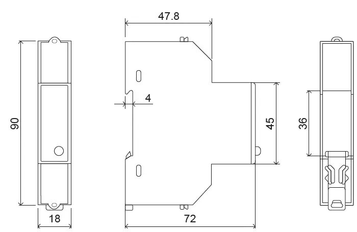 Figure 12: Dimensions of the CEM-C12
MAINTENANCE AND TECHNICAL SERVICE
In the case of any query in relation to device operation or malfunction, please contact the CIRCUTOR, SA Technical Support Service.
Technical Assistance Service
Vial Sant Jordi, s/n, 08232 – Viladecavalls (Barcelona)
Tel: 902 449 459 ( España) / +34 937 452 919 (outside of Spain)
email: [email protected]
GUARANTEE
CIRCUTOR guarantees its products against any manufacturing defect for two years after the delivery of the units.
CIRCUTOR will repair or replace any defective factory product returned during the guarantee period.
- No returns will be accepted and no unit will be repaired or replaced if it is not accompanied by a report indicating the defect detected or the reason for the return.
- The guarantee will be void if the units has been improperly used or the storage, installation and maintenance instructions listed in this manual have not been followed. “Improper usage” is defined as any operating or storage condition contrary to the national electrical code or that surpasses the limits indicated in the technical and environmental features of this manual.
- CIRCUTOR accepts no liability due to the possible damage to the unit or other parts of the installation, nor will it cover any possible sanctions derived from a possible failure, improper installation or “improper usage” of the unit. Consequently, this guarantee does not apply to failures occurring in the following cases:
- Over voltages and/or electrical disturbances in the supply;
- Water, if the product does not have the appropriate IP classification;
- Poor ventilation and/or excessive temperatures;
- Improper installation and/or lack of maintenance;
- Buyer repairs or modifications without the manufacturer’s authorization.
CE CERTIFICATE
EU DECLARATION OF CONFORMITY
This declaration of conformity is issued under the sole responsibility of CIRCUTOR with registered address at Vial Sant Jordi, s/n – 08232 Viladecavalls (Barcelona) Spain.
Product:
Single-phase energy meter
Series:
CEM-C4-MID, CEM-CG-MID, CEM-CG-MID-ST,
CEM-C12-MID
Brand:
CIRCUTOR
The object of the declaration is in conformity with the relevant EU harmonization legislation, provided that ii is installed , maintained and used for the application for which it was manufactured, in accordance with the applicable installation standards and the manufacturer’s instruction
2014/32/CE: Measuring Instrument Directive 2011/65/EU: RoHS2 Directive
2015/863/EU: RoHS3 Directive
It is in conformity with the following standard(s) or other regulatory document(s):
EN 50470-1:2006 EN 50470-3:200
Year of CE mark:
2022
Viladecavalls (Spain), 30/3/2022
General Manager: Ferran Gil Tome
CIRCUTOR, SA
Vial Sant Jordi, s/n
08232 -Viladecavalls (Barcelona)
Tel.: (+34) 93 745 29 00 – Fax: (+34) 93 745 29 14
www.circutor.com [email protected]..


 Aeoezw095c3a200 Manual")
 Aeoezw095c1a200 Manual")
 Aeoezw095c1a100 Manual")
 Aeoezw095c3a100 Manual")
 Aeoezw095c3a60 Manual")
 Aeoezw095c1a60 Manual")


