KIBANI BH65b-200 Air Compressor
Operating Instructions
Please read these instructions carefully before attempting to assemble, install, operate or maintain the product described. Protect yourself and other people by observing all safety information. Failure to comply with instructions could result in personal injury and/or property damage! Retain instructions for future reference.
DESCRIPTION
Belt drive, Oil lubrication air compressors are designed for professional market with a variety of home, and automotive work. These compressors can drive spray guns, impact wrenches, nail guns, hammer gun, sandblaster and other tools. Wet Compressed air(<8.0bar or <12.5 bar) can be supplied by these compressors, Set up a water filter or air dryer between compressor and power tools if the power tools need dry air.
SAFETY GUIDELINES
This manual contains very important information need to read and understand. This information is provided for SAFETY and to PREVENT EQUIPMENT PROBLEMS. Following symbols are help for understanding this information.
- DANGER!
Danger indicates an imminently hazardous situation, which, if not avoided, will result in death or serious injury. - WARNING!
Warning indicates a potentially hazardous situation, which, if not avoided, could result in death or serious injury. - CAUTION!
Caution indicates a hazardous situation, which, if not avoided, MAY result in minor or moderate injury. - NOTICE!
Notice indicates important information that if not followed, MAY cause damage to equipment. - Unpicking
Before and after unpacking the package, inspect carefully for any damage that may have occurred during transit. Make sure fittings, bolts and so on are tight before putting compressor into service. - WARNING!
Do not operate compressor if it have been damaged during shipping. Handling or use, these damages may result in bursting and cause injury or property damage. - DANGER!
Breathable Air Warning This compressor is not equipped and should not be used “as is” to supply breathing quality air. For any application of air for human consumption, the air compressor will need to be fitted with suitable in-line safety and alarm equipment. This additional equipment is necessary to properly filter and purify the air to meet minimal specifications for local standard.
GENERAL SAFETY INFORMATION
Since the air compressor and other components (material pump, spray guns, filters, lubricators, hoses, etc.) used, set up a high pressure pumping system, the following safety precautions must be observed at all times:
- Read all manuals included with this product carefully. Be thoroughly familiar with the controls and the proper use of the equipment.
- Follow all local electrical and safety codes as well as in the US, National Electrical Codes (NEC) and Occupational safety and Health Act (OSHA).
- Only persons well acquainted with these rules of safe operation should be allowed to use the compressor.
- Keep visitors away and NEVER allow children in the work area.
- Wear safety glasses and use hearing protection when operating the pump or unit.
- Do not stand on or use the pump or unit as a handhold.
- Before each use, inspect compressed air system and electrical components for signs of damage, deterioration, weakness or leakage, Repair or replace defective items before using
- Check all fasteners at frequent intervals for proper tightness.
WARNING!
Motors, electrical equipment and controls can cause electrical arcs that will ignite a flammable gas or vapor. Never operate or repair in or near a flammable gas or vapor. Never store flammable liquids, gases or material in the vicinity of the compressor.
CAUTION!
Compressor parts may be hot even if the unit is stopped. - Keep fingers away from a running compressor, fast moving and hot parts will cause injury and/or burns.
- If the equipment should start to abnormally vibrate, STOP the engine/motor and check immediately for the cause, vibration is generally a warning of trouble.
- To reduce fire hazard, keep engine/motor exterior free of oil, solvent, or excessive grease. WARNING!
Never remove or attempt to adjust safety valve. Keep safety valve free from paint and other accumulations.
DANGER!
Never attempt to repair or modify a tank! Welding, drilling or any other modification will weaken the tank resulting in damage from rupture or explosion. Always replace worn or damaged tanks.
WARNING!
Drain liquid from tank daily. - Tank rust from moisture build-up, which weakens the tank. Make sure to drain tank regularly and inspect periodically for unsafe conditions such as rust formation and corrosion.
- Fast moving air will stir up dust and debris, which may be harmful. Release air slowly when draining moisture or depressurizing the compressor system.
SPRAYING PRECAUTIONS
WARNING!
Do not spray flammable materials in vicinity of open flame or near ignition sources including the compressor unit.
- Do not smoke when spraying paint, insecticides, or other flammable substances.
- Use a face mask/respirator when spraying and spray in a well ventilated area to prevent health and fire hazards.
- Do not direct paint or spray other sprayed material at the compressor. Locate compressor as far away from the spraying area as possible to minimize overspray accumulation on the compressor.
- When spraying or cleaning with solvents or toxic chemicals, follow the instructions provided by the chemical manufacturer.
ASSEMBLY
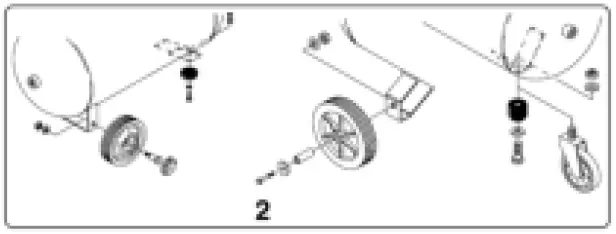
WHEELS ASSEMBLY
Assemble and fasten the wheels and rubber feet before using compressor. Make sure the compressor is horizontal and stable.

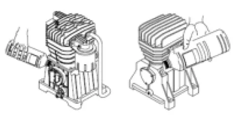
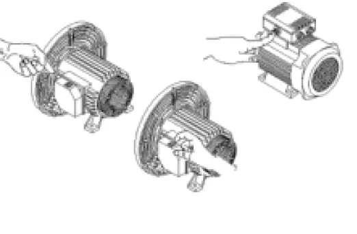
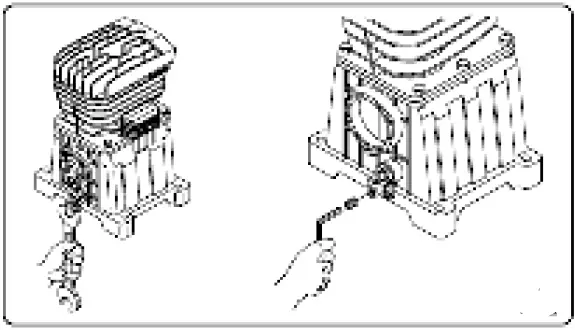
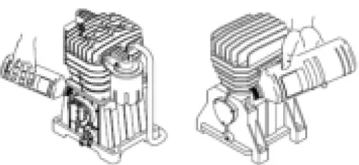
AIR FILTER ASSEMBLY
Move the transport plug. Fit and fasten air filter s in cylinder head.
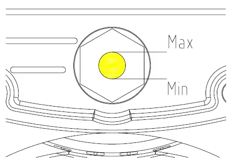
OIL
Check oil level, Add air compressor oil from oil hole(if possible), Make sure the oil level higher than middle line of oil lever.
INSTALLATION
LOCATION
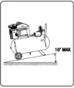
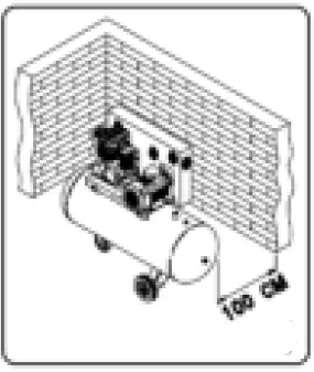
It is extremely important to install the compressor in a clean, well ventilated area where the surrounding air temperature will not be high than 40°C. A minimum distance of 1 meter between the compressor and objects is required because objects could obstruct airflow. Locate compressor on a horizontal ground.
CAUTION!
Do not locate the air inlet of compressor near steam, paint spray, sawdust sandblast areas or any other source of contamination. This debris will damage the motor.
ELECTRICAL INSTALLATION
WARNING!
All wiring and electrical connections should be performed by a qualified electrician. Installation must be in accordance with local codes and national electrical codes.
CAUTION!
Never use an extension power cord with this product. Use additional air hose instead of an extension power cord to avoid power loss and permanent motor damage; Use of an extension power cord voids the warranty.
ADJUST THE BELT:
Belt need to be adjusted in a line, adjust the tension as following requirement: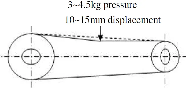
GROUNDING INSTRUCTIONS
This product is for use on a nominal 110V~240V circuit and has a grounding plug that looks like the plug illustrated in Fig.5. Make sure the product is connected to an outlet having the same configuration as the plug. This product must be grounded. In the event of an electrical short circuit, grounding reduces risk of electrical shock by providing an escape wire for electric current. This product is equipped with a cord having a grounding wire with an appropriate grounding wire with an appropriate grounding plug. Plug must be plugged into an outlet that is properly installed and grounded in accordance with all local codes and ordinances.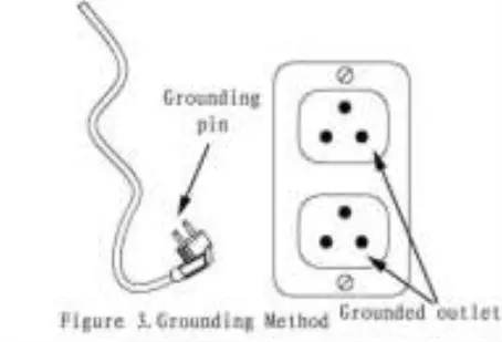
DANGER!
Improper use of grounding plug can result in a possible risk of electrical shock!
DANGER!
Do not use a grounding adapter with this product! If repair or replacement of power cord or plug is necessary, do not connect grounding wire to either flat blade terminal. The wire with insulation having an external surface that is green (with or without yellow stripes) is the grounding wire.
WARNING!
Never connect green (or green and yellow) wire to a live terminal.
Check with a qualified electrician or service man if grounding instructions not completely understood or in doubt as to whether product is properly grounded. Never modify the plug receptacle privately; if there are not fitting outlet, make proper outlet installed by a qualified electrician.
WARNING!
- Local electrical wiring codes differ from area to area. Source wiring, plug and protector must be rated for at least the amperage and voltage indicated on motor nameplate, and meet all electrical codes for this minimum,
- Use a slow blow fuse or a circuit breaker.
CAUTION!
Overheating, short circuiting and fire damage will result from inadequate wiring, etc.
NOTE:
230 volt, 5 amp units can be operated on a 230volt circuit under the following conditions:
- No other electrical appliances or lights are connected to the same branch circuit.
- Voltage supply is normal.
- Circuit is equipped with a 5 amp circuit breaker or a 15 amp slow blow fuse.
If these conditions cannot be met or if disconnection of current protection device occurs, it may be necessary to operate compressor from a 230 volt, 5 amp circuits.
OPERATION
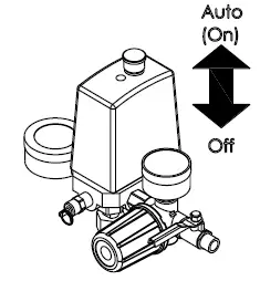
Pressure Switch-Auto/Off Switch-In the “AUTO” position, the compressor shuts off automatically when tank pressure reaches the maximum preset pressure (0.8Mpa) and runs automatically when tank pressure reaches the minimum preset pressure (about 0.6Mpa). In the “OFF” position, the compressor will not operate. This switch must be in the “OFF” position when connecting or disconnecting the power cord from the electrical outlet or when changing air tools.
- Regulator
The regulator use to adjust pressure of outlet to fitting air-power tools. Safety Valve- It release compressed air automatically when pressure in tank exceeds allowing pressure. - Discharge Pipe
Discharge pipe connects pump to check valve. It is hot when compressor is running. To avoid grievous burn, never touch discharge pipe. - Check Valve
Check valve is a one-way valve allowing compressed air go ahead to the tank, but prevents compressed air in tank back to pump. - Belt Vover
Designed to protect pulley and belt. - Handle and wheels
Designed to move the compressor easily.
WARNING!
Never use the handle on wheeled units to lift the unit completely off the ground. - Reset switch
Designed to protect to motor when the power circuit is too low, or compressor is overloading.
CAUTION!
If the compressor can not be started when it is connect with power, check the reset switch firstly.
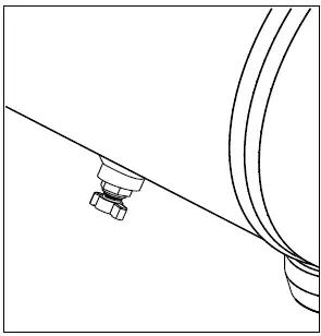
- Drain Valve
locate at bottom of the tank, used to exhaust water from tank. Make sure the pressure of tank is below 1 bar, open drain valve to exhaust water from tank. Then close it tightly. This action should be done every week.
- ADD OIL
Air compressor oil is suggested to use. Keep the oil level higher than the red cycle or middle lever of oil glass (the oil level need to be checked and added every week). - OIL Replacing
Replace the oil every 6 months


BREAK-IN PROCEDURE
CAUTION!
Do not attach air chuck or other tools to the outlet until unit have been checked and start procedure has been completed.
IMPORTANT: Do not operate compressor before reading instructions, otherwise damage may result.
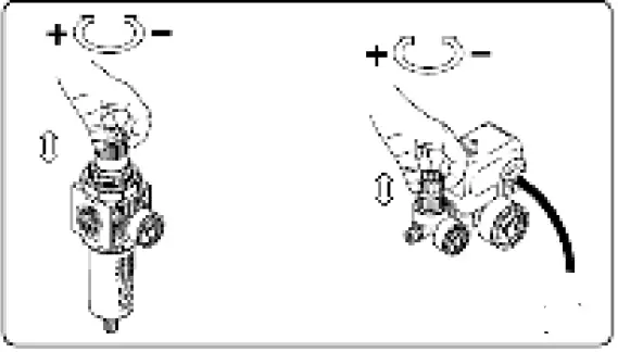
- Turn regulator fully clockwise to open airflow.
- Turn switch to OFF position and plug in power cord.
- Turn switch to AUTO position and run unit for 30 minutes to run the pump parts without pressure.
- Turn regulator knob fully counterclockwise. Compressor will build to maximum preset pressure and shut off.

- Turn regulator knob clockwise to bleed off air. Compressor will restart at a preset pressure (about 6.0bar).
- Turn regulator knob counterclockwise to shut off the air and turn switch to off position.
- Attach chuck or other tool to outside. Open the pressure switch to AUTO position, the compressor starts work and pumps air into the tank. It shuts off automatically when unit reaches its maximum preset pressure. In the OFF position, the pressure switch cannot function and the compressor will not operate. Make sure switch is in OFF position when connecting or disconnecting power cord to electrical receptacle.
MOISTURE IN COMPRESSED AIR
Moisture in the air will change to water when air is compressed or temperature is drop. When humidity is high or when a compressor is in continuous use for a long time, water will collect in the tank. If you use a paint spray or sandblast gun, Moisture will be carried from the tank through the hose, and out of the gun as water mixed with the spray material.
IMPORTANT: This condensation will cause water spots in a paint job, especially when spraying other than water based paints. If sandblasting, it will cause the sand to case and clog the gun rendering it ineffective. A dry filter in the air line, located nearby the gun as possible, will help eliminate this moisture.
SAFETY VALVE
WARNING!
- Never remove or attempt to adjust the safety valve! Safety valve should be checked under pressure occasionally by pulling the ring by hand. If air leakage after ring has been released, or valve is stuck and cannot be actuated by ring, it MUST be replaced.
- If the safety valve start operation automatically, shut up the motor and check the reason. Never use the compressor if safety valve operated.
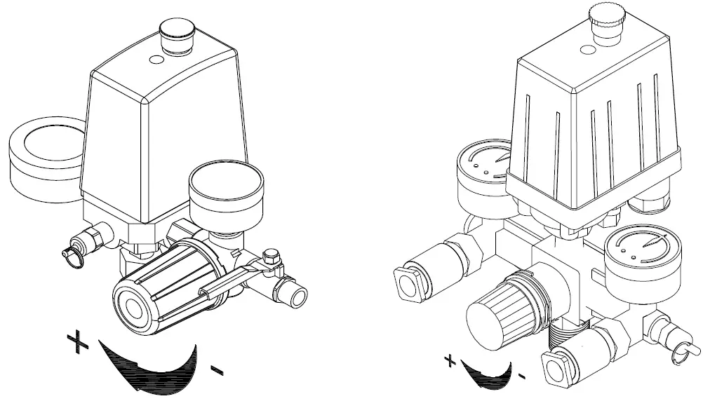
REGULATOR
- Regulator adjusts air pressure to fit an air-operated tool or paint spray gun.
- Adjust outlet air pressure by turn the knob


PRESSURE GAUGE
There are 1 or 2 gauges on this type of compressor, one shows pressure in tank and another one (if there are 2 gauges) shows outlet’s pressure after regulator.
MAINTENANCE
WARNING!
Disconnect power source, release all pressure from the system before attempting to install, service, relocate or perform any maintenance. Check compressor often for any visible problems and follow maintenance procedures each time compressor is used.
- Pull ring on safety valve and allow it to snap back to normal position.
WARNING!
Safety valve must be replaced if it cannot be actuated or it leaks air after ring is released. - Turn compressor off and release pressure from system. Drain moisture from tank by opening drain valve underneath tank.
- Clean dust and dirt from motor, tank, and airlines and pump cooling fins while compressor is still OFF.
WARNING!
Never put your handle into the running parts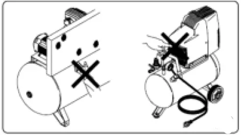 IMPORTANT:
Locate unit as far from spraying area, as hose will allow preventing overspray from clogging filter.
LUBRICATION
SAE30 oil or Air Compressor oil is suggested to use. Keep the oil’s level higher than the red cycle or middle line of oil glass.
THERMAL OVERLOAD PROTECTOR
CAUTION!
This compressor is equipped with an automatic reset thermal overload protector, which will shut off motor if it becomes overheated.
If thermal overload protector shuts motor OFF frequently, look for the following causes.
- Low voltage.
- Motor problem.
- Lack of proper ventilation.
CAUTION!
If the thermal overload protector is actuated, the motor must be allowed to cool down before start-up is possible. The motor will automatically restart without warning if left plugged into electrical outlet and unit is turned on.
STORAGE
- Store hose and compressor in a cool dry place when there are not in use.
- Exhaust water from tank.
- Disconnect hose and hang it on top of compressor, to avoid damage.
PROBLEM LIST
| Symptom | Possible Cause (s) | Corrective Action |
| Compressor cannot start/restart |
|
|
| Motor stalls or runs slowly |
|
DANGER! Never disassemble check valve under pressure. release tank firstly |
| Fuses blow/circuit breaker trips repeatedly. CAUTION! Never use an extension cord with this product |
|
DANGER! Never disassemble check valve under pressure. release tank firstly |
| Thermal overload protector cuts out repeatedly |
|
DANGER! Never disassemble check valve under pressure. release tank firstly |
| Knocks, rattles, excessive vibration |
|
|
| Tank pressure drops when compressor shuts off |
|
|
| Compressor runs continuously and air flow is lower than normal/low discharge pressure |
|
|
| Excessive moisture in discharge air |
|
NOTE: Water condensation is not caused by compressor malfunction |
| Compressor runs continuously and safety valve opens as pressure rises |
|
|
| Excessive starting and stopping (auto start) | Excessive condensation in tank | Drain more often |
| Air leak from release valve under pressure switch when the compressor is power off. | Check valve stuck in an open position | Replace check valve DANGER! Never disassemble check valve under pressure. release tank firstly |
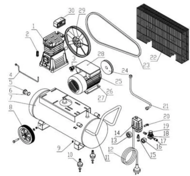
Main Exploded-Drawing of Belt-Driven Model
Main Exploded-Drawing of Belt-Driven Model
| Parts List | ||||||||
| NO | PART | UNIT | QTY | NO | PART | UNIT | QTY | |
| 1 | BH65 Pump Head | SET | 1 | 16 | Pressure Gauge 40 | PC | 1 | |
| 2 | Oil breather | PC | 1 | 17 | Quick coupler | PC | 2 | |
| 3 | One-Way Valve | SET | 1 | 18 | Regulator | PC | 1 | |
| 4 | Release Tube | PC | 1 | 19 | 1/4 Connector | PC | 1 | |
| 5 | Tank Plug | PC | 1 | 20 | Safety Valve | PC | 1 | |
| 6 | O ring for tank | PC | 1 | 21 | Discharge Tube | PC | 1 | |
| 7 | Tank | PC | 1 | 22 | Belt cover | SET | 1 | |
| 8 | Wheel | SET | 2 | 23 | Belt | PC | 1 | |
| 9 | Drain Valve | PC | 1 | 24 | Motor Pully | PC | 1 | |
| 10 | Foot pad | SET | 2 | 25 | Motor | SET | 1 | |
| 11 | Handle | PC | 1 | 26 | Start capacitor | SET | 1 | |
| 12 | Power Cord | PC | 1 | 27 | Run Capacitor | PC | 1 | |
| 13 | Pressure Gauge 50 | PC | 1 | 28 | Capacitor Cover | SET | 1 | |
| 14 | Pressure Switch | PC | 1 | 29 | Pump pully | PC | 1 | |
| 15 | PS Connector | SET | 1 | 30 | Air Filter | SET | 1 | |


