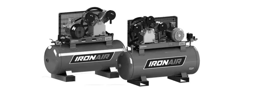
IRONAIR LB50270S3 Air Compressor 
INSTRUCTION MANUAL
Forward
This manual is an integral part of your compressor that should be retained for future reference. Before operating your compressor read this manual carefully so as you are aware of its correct operation. If you are unclear on any feature please consult your dealer. The manual also contains information regarding safe operation and warnings with which you need to be familiar. You will also find simple maintenance procedures which if followed will prolong the life of your compressor and validate your warranty. The manual contains a spare parts list & drawings which are available from your dealer.
Important Information
- Understand all operating procedures, safety precautions and warnings before operation.
- Most accidents occur as a result of failure to observe basic safety rules and precautions
- Accidents can often be avoided by recognising potentially hazardous situations before they occur
- Basic safety precautions are outlined in the “General Safety Warnings” section of this manual
- Hazards that can potentially cause injury or damage to the compressor are identified by warning labels on the compressor and in this manual.
- Never use the compressor in a manner or for purposes that it has not been designed for or recommneded by the manufacturer.
- For three phase (415V) models the “Warranty Requirements” checklist must be validated. Your copy and the dealers copy of the checklist is included with the compressor. You must ask your dealer if you cannot locate it.
- A Plant Risk Assessment is also available for this compressor and should be read and understood in conjunction with this owner’s manual. Recommendations are made specifically regarding the workplace in addition to what is provided in this manual. Contact your place of purchase to secure your copy for your workplace.
Warning Labels
Read the Instruction Manual – Before positioning, operating or adjusting the compressor.
Risk of Electric Shock – Caution! Before commencing any tasks on your compressor it must be disconnected from the power/electricity supply
Risk of Accidental Start Up – Caution! Your compressor can start automatically without warning, it is designed to restart when it reaches its minimum preset pressure. It may start after a power blackout and subsequent power re-supply.
Risk of High Temperatures – Caution! Your compressor has some parts which reach high temperatures that can cause burns.
Protective Gear Required – Caution! Ensure you wear the correct protective gear when operating the compressor (hearing and eye protection and dust mask).
Risk of Pressurised Parts – Caution! Some parts and components of your compressor are under high pressure which if damaged or tampered with may cause injury.
General Warning – Refer to the safety instructions that must be complied with in order to protect the operator and personal in the work place.
Moving Parts – Fan and Belt Guards– Caution! Take care around moving parts such as fans and belts. Secure fan and belt guards before operating compressor. Ensure you are not wearing loose clothing or jewellery and long hair is tied back or in a hair net.
Misuse – Compressor must be used safely, misuse may result in injury. Do not direct com pressed air at any person or animal.
Note– Refer to recommended instructions and precautionary measures to facilitate maintenance and special procedures.
Specialised Personnel – Refer to operations that should be carried out by authorised service agents only. Service & Spare Parts – Use only original spare parts from your dealer or authorised service agent. Failure to do so may void your warranty and/or cause damage to your compressor.
Description
Your Compressor belongs to the piston/belt driven/reciprocating class. High pressure (lObar and above) compressors are two stage. All compressors are on tanks that are manufactured according to Australian Standard AS-1210-2010. All compressors have their F.A.D. (Free Air Delivery) rated in accordance with Australian Standard AS-4637-2006 which makes it easy for you to identify what air equipment your compressor is capable of operating.
Designed Usage
Your compressor is designed to operate a variety of pneumatic tools & equipment. Such tools require different air volumes and pressures to operate correctly. Technical data of pneumatic tools and equipment should be provided by the manufacturer. Your dealer will assist you in making the correct choice or give you the correct advice if you are uncertain. Compressor pumps are designed for intermittent duty applications. It is recommended that your compressor duty cycle never exceed 50%. This means that for a given time period such as a working day, your compressor should not operate for more than half of that time. It is also recommended that within that time period your compressor should not run continuously for more than 15 minutes.
Leaking air lines or poor installation may cause your compressor to run excessively. Always check for leaks. Your compressor should be switched off when unattended or not in use.
Supplied with Compressor
- Instruction Manual
- High flow quick connect coupler or couplers
- Manufactures data sheet for tank design.
- Tank pressure gauge.
General Safety Warnings
- Read the instruction manual prior to use, ensure all operators are trained and experienced in the operation of the compressor and have read the instruction manual.
- Learn how to operate all controls and how to stop the compressor in case of emergency.
- Before commencing any service, routine maintenance or inspection, ensure that your compressor is turned off, the power supply is disconnected and all pressure has been
- released from the tank.
- After all maintenance operations ensure that all components have been fitted correctly .
- Ensure compressor is assembled according to the manufacturer’s instructions .
- Always wear correct safety gear when operating the compressor (hearing protection, safety glasses, dust masks).
- Do not wear loose clothing or jewellery and keep long hair tied back or in a hair net when op erating compressor.
- Do not allow infants, animals or anyone who is not authorised by you to operate or be in the operating area of your compressor.
- For ALL models always turn the compressor on and off using the knob on top of the pressure switch.
- Avoid electrocution! Never use your compressor if the electrical cord or electrical components are frayed or damaged in any manner. Inspect all cords regularly.
- Never spray paint in confined areas or near naked flames .
- Do not touch the cylinder heads, cooling fins and feed pipes during operation. They will be hot and may cause burns. Even when your compressor has been turned off these parts retain heat for some time.
- Do not leave flammable or plastic objects near your compressor.
- Never move your compressor with pressure still in the tank.
- The compressor must be moved or lifted using a forklift or other correct lifting equipment and techniques to avoid damaging the compressor in any way.
- Never direct pressurised air at any person or animal.
- Never allow any person to operate your compressor unless they have read and understand this manual.
- Keep hands and loose objects clear of moving parts .
- Never operate your compressor without air filters .
- Never operate your compressor without the correct guards on moving parts and covers on electrical components.
- Never tamper with or attempt to adjust the pressure safety valve or valves .
- Never connect to your compressor an air line or hose that can not withstand the air flow rate and pressure that your compressor can deliver.
TRANSPORT AND HANDLING
Unpacking
Depending on the model, your compressor may be packed on a wooden pallet with a cardboard cover or in a cardboard box. All packaging is marked showing the correct way up and the weight of the compressor. Always ensure that the compressor us the correct way up before unpacking. If you store your compressor before unpacking it, ensure it is kept in a dry place with a surrounding temperature between 0-35 degrees celsius. If your compressor is stored for long periods it is recommended that the oil be replaced prior to commissioning. Ensure to wear safety glasses when cutting packaging straps. After removing the cardboard cover or open the top of the box, lift it out of the box with adequate assistance (use a suitable mechanical lifting device if the compressor is too heavy, ensure the lifting device is operated by qualified personnel). Secure the wheels, vibration dampers and or rubber pads. Compressors with tanks exceeding l00lt capacity can be awkward to handle. Ensure that you keep the compressor well balanced at all times.
Disposal of Packaging
We recommend that you retain the packaging material for at least the warranty period. If disposing the packaging please do so in a correct manner that is friendly to the environment.
Scheduled Maintenance Table
| Maintenance operations | Every week | Every month | Every 6 months | Every 2 years |
| Checking the oil level | Tick | |||
| Draining the condensation | Tick | |||
| Cleaning the intake filter | Tick | |||
| General cleaning of compressor | Tick | |||
| Replacing the oil | Tick | |||
| Check belt tension | Tick | |||
| Check non return valve | Tick |
Standardized to DIN 51506 and ISO/DP6521.3
Recommended Oils
| Compressor model | Drive rating | Viscosity grade |
| Oil piston air cooling | < 20 KW | 68, 100, 150 |
Room temperature below +5°C: ISO 68
Room temperature above +6°C: ISO 100
Room temperature above +25°C: ISO 150
| AGIP | DICREAl00 | MOBIL | RARUS 427 |
| BP | ENERGOL CSl00 | FINA | EOLAN AC 100 |
| SHELL | COREMA OIL Hl0 | CASTROL | AIRCOL PDl00 |
| ESSO | EXXC OLUB HlS0 | TOTAL | CORTUSA 100 |
| FUCHX | RENOLIN 104L VG 100 | API | CM-8X |
| IP | CALATIA OIL ISO 100 |
(Suitable for room temperature ranging from +5°C to +25°C)
Maintenance
Warning
In order to keep your compressor in good working condition, periodic service procedures must be performed. Before performing any maintenance operation make sure the compressor is switched off; isolated from the mains power and all the air in the tank has been released.
First 50 Hours
- Check that all screws and bolts are tight, paying special attention to the head and crankcase.
- Replace the oil with one of the recommended oils listed in the schedule on page 5 or one supplied by your dealer.
- Never mix different oils together.
- Dispose of waste oil correctly and in a manner that is environmentally responsible.
Weekly
- Check the oil level. Top up if necessary.
- Do not exceed the maximum level mark.
- Drain condensation by opening the drain cock located under the tank, when all the
condensate is drained and only air is released close the drain cock. If your compressor is fitted with a filter/regulator the drain cock at the base of the filter bowl should also be opened and the condensate released. Compressor condensate can pollute and should be disposed of in a manner that is environmentally responsible.
Monthly
- Remove the air filter and clean or replace the filter element. Paper elements should be blown out with compressed air from the inside towards the outside then refitted.
- Sponge or foam elements should be washed in a solution of warm water and detergent, then rinsed and dried before refitting.
- Metal elements should be washed with degreaser then blown clean with compressed air.
- Do not operate your compressor without air filters. Foreign bodies and dust can seriously damage inside components.
Six Month
- Change the oil. Best performed when the compressor is warm or hot as the viscosity of the oil is less.
- Remove the dipstick or oil breather then unscrew and remove the sump drain plug.
- Drain the oil into a container.
- Replace the sump drain plug and pour clean oil into crankcase through the dipstick or oil breather opening until the maximum level is reached.
- Dispose of waste oil correctly and in a manner that is environmentally responsible.
- Clean all finned cooling parts with compressed air.
- Check the belt tension. Apply approximately 2.5kg force to the mid section of the pulley belt. The belt should flex approximately Smm. If necessary tighten the belt tension ensuring that the alignment of the motor and pump pulleys are correct.
Two Years
- Check the non return valve.
- MAKE SURE THAT ALL AIR HAS BEEN RELEASED FROM THE TANK!!!
- Inspect the seal and replace if worn.
- Check intake and delivery valves.
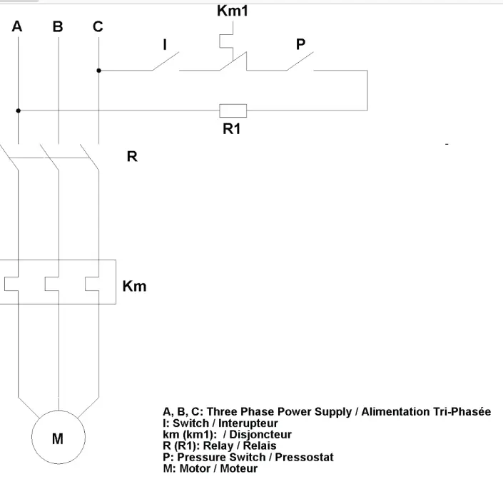
Wiring Diagram
SETTING UP AND COMMISSIONING
Positioning
Your compressor should be placed on a level surface. Inclines greater than 15 degrees will cause damage, b) Your compressor requires ventilation. Ensure that all flywheels, fans and cooling grills are unobstructed by any obstacles that may prevent air flow. c) Ensure that your compressor is in an environment that has clean air with a surrounding temperature between 5 -30 degrees Celsius.
Commissioning
All compressors are pretested prior to delivery. To ensure that your compressor performs to the level that it was designed to, follow hereinafter instructions:
- Check the oil level; check through the sight glass on the side of the compressor’s pump or use the crankcase dip-stick. Oil should be up to MAX level.
- After the first 50 hours of running replace the oil with one listed on page 5. Your dealer stocks replacement oil.
- Check the label on the electric motor and ensure that your mains power supply is adequate and correct. Mains power should be provided through a plug that is connected via fuses and an earth connection
- Three phase models are not supplied with a plug. Your compressor should not be directly connected to the mains power; it should be fitted with a three phase plug so it can be isolated. Plugs and connections should be fitted by a licensed electrician. 5hp models should have a minimum l0amp plug and 7.5hp and l0hp should have a minimum 15amp plug.
- Check that the drain plug on the underside of the tank is closed.
Starting
When you have commissioned your compressor, check that the main switch (for 3 phase models) and the pressure switch are in the off or “O”position. Plug in your compressor to the mains power and switch the main switch (for 3 phase models) then the pressure switch on or to the “I” position.
When starting your compressor for the first time allow it to run continuously for approximately 10 minutes by opening the ball valve or the pressure regulator. (If a quick connector is fitted to the pressure regulator air will not pass through the connector, in this case the male part of the connector should be inserted to keep the connector valve open). After approximately 10 minutes running, close the ball valve or pressure regulator (remove the male part of the quick connector) and check using the pressure gauge that the tank pressure increases.
The pump should automatically stop when the tank maximum pressure has been reached. You will now appreciate how simple it is to use your compressor. The pressure switch is factory set to cut the power to the electric motor when the tank maximum pressure has been reached. As you use the stored air in the tank the pressure switch will cut-in automatically when the pressure drops below the minimum setting, this is normally 2Bar (30p.s.i.) below the maximum setting Never stop your compressor using the mains power switch or by unplugging it. Your compressor should be stopped by turning the mains switch to the off or “O” position.
Working Pressure
Three phase models are fitted with a magnetic overload cut-out and automatic starter. The heat relay will stop the motor in the event of an overload. Should this occur contact your dealer, authorised service agent or a licensed electrician to have the relay setting checked and replaced if necessary. NOTE: on models fitted with an oil control system, low oil levels may cause the power cut out. Check the oil level before resetting the relay. If the problem persists switch off your compressor, disconnect it from the mains power and contact your dealer or authorised service agent.
Working Pressure
Pneumatic tools and equipment operate with at a variety of pressure settings. The working pressure of you compressor can be set by adjusting the pressure regulator or filter/regulator. Check the recommended operating pressure of the tools or equipment that you are going to use. Adjust the pressure regulator or filter/regulator by turning the knob clockwise to increase the pressure or anti-clockwise to reduce it. For filter/regulators the adjustment knob can be locked by depressing it or unlocked by pulling it up. The working pressure can be checked with the pressure gauge fitted to the regulator. When you have finished using your compressor set the working pressure to zero, this will avoid damage to the regulator. For compressors where air is taken directly from the tank or ball valve by-passing the pressure regulator, additional regulators and filters can be fitted along the air supply line. Your dealer can advise you on the best way to do this.
Pneumatic Connections
Always use air pipe, hose couplings and fittings that are designed to withstand the maximum pressure that your compressor can deliver. If you are unsure check with your dealer. Never repair faulty pneumatic connections.
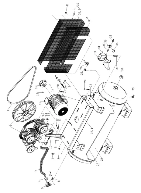
PARTS LIST-COMPRESSOR
Model: LB50270S3 W0.90 LB32270S3 W0.67
| No _ | Q_t!f | Part no_ | Part N ame |
| 1 | 2 | 441m88000mm | V-Helt for 0_91 |
| 1 | 2 | 441 B·118 0 ) 0000 | V-Belt for 0.67 |
| 2 | 1 | 3500908890000 | Bare IPu mp,0_9 |
| 2 | 1 | 85006188009 0 | Bare 1Pu mp,{l 67 |
| 3 | 1 | 4682080000000 | Copper Tube |
| 4 | 2 | 4690040000000 | Leck nut |
| 5 | 1 | 47)0250000000 | Chedk!M’al\rie |
| 6 | 1 | 46.518,063 000000 | NU)p le |
| 7 | 1 | 4703810000000 | s aieti; V.alve |
| 8 | 8 | 4611003{)00 000 | Nut |
| 9 | 5 | 4600201604000 | Sonew |
| 10 | 1 | 3490030000000 | Bracket,be, lt guard |
| 11 | 9 | 3490030000000 | Belt guard was.her |
| 12 | 9 | 4600601206000 | S onew |
| 13 | 12 | 6031790000000 | Washer |
| 14 | 12 | 4661002000000 | S!plfirng Washer |
| 1.5 | 4 | 4601004001000 | Sonew |
| 16 | 1 | 4910015 2020 0 | Motor–, 0_9 |
| 16 | 1 | 49100 55403000 | Motor-, (l 67 |
| 17 | 1 | 4640225000000 | K1ey |
| 18 | 1 | 446B214 ooom m | Motor- Pul ey o_g |
| 18 | 1 | 446B21300DOOO | Motor- IPu l ey 0_67 |
| rn | 1 | 469022000000 | Siet Screw |
| 20 | 4 | 4611006{)00 000 | Nut |
| 21 | 1 | 822102100000 | Motor shake handshan dle |
| 22 | 1 | 4620216{)00 000 | Washer plate |
| 23 | 4 | 4601003{)0 4 000 | Nut,Hlex |
| 24 | 4 | 4601004003000 | Sonew |
| 25 | 1 | 4290430000000 | Ellbow |
| 26 | 1 | 4740010000000 | Baml Valve |
| 27 | 1 | 120611mmmmo | Tube |
| 2,8 | 1 | 81 10’9081900000 | Air– T an‘k 270L |
| 28.1 | 1 | 8073009000000 | Bsae pl:ate |
| 29 | 1 | 4723600000000 | Drain !la e |
| 30 | 2 | 43)0210000000 | Pilug,sodke.t head |
| 31 | 1 | 43536140000DO | NU)ple |
| 32 | 1 | 430.2501403000 | Piressur-e ,g,aug e |
| 33 | 1 | 200.205 1100000 | Piressur-e switch |
| 34 | 1 | 43)0140200000 | Pilug |
| 3.5 | 1 | 4351403{)00 000 | NU)ple |
| 36 | 1 | 4710020000000 | Piressur-e ragul:ator |
| 37 | 1 | 4091250000000 | QllJ ick coupleJ |
| 18 | 1 | 430.25014 0 4 000 | Piressur-e Ga1JJg 1e |
| J,19 | 1 | 34)0900500000 | B1elt guard |
| J,19.1 | 1 | 34)0’900500010 | B1elt guard FIR) |
| J,19.2 | 1 | 34)0900500002 | 8elt guard RR) |
| 40 | 11) | 3490040000000 | Belt Guard clip |
EXPLOSION VIEW-PUMP Model:W-0.90
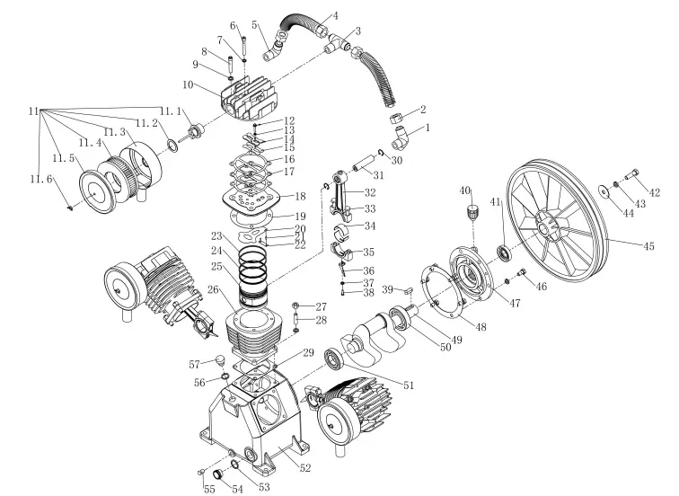
PARTS LIST-PUMP Model:W-0.90
| No. Q.ty | Part no. | Part Name |
| 1 | 4213412300000 | 3-way manifold nipple |
| 2 4 | 4690040000000 | Nut |
| 3 1 | 4213418300000 | 3-way manifold nipple |
| 4 2 | 4682022601000 | Copper tube.Inter discharge |
| 5 1 | 4213409200000 | Elbow fitting |
| 6 3 | 4608060000000 | Head bolt |
| 7 3 | 4660801000000 | Spring washer |
| 8 12 | 4601005000000 | Head.bolt |
| 9 30 | 4661000000000 | Spring washer |
| 10 3 | 8370090010000 | Cylinder head |
| 11 3 | 4341115000000 | Intake filter Ass’Y |
| 11.1 3 | 4341115001001 | Support,lntake filter |
| 11.2 3 | 4341115001002 | Seal,lntake filter |
| 11.3 3 | 4341115001003 | Filter case |
| 11.4 3 | 4341115001004 | Element |
| 11.5 3 | 4341115001005 | Filter cover |
| 11.6 3 | 4341115001006 | Nut,Butterfly |
| 12 6 | 4600501607000 | Screw |
| No. | Q.ty | Part no. | Part Name |
| 13 | 6 | 4660500000000 | Spring washer |
| 14 | 3 | 4290900000000 | Valve holder |
| 15 | 3 | 4170901000000 | Blade,valve |
| 16 | 6 | 4240901000000 | Gasket, Head |
| 17 | 3 | 4221090030000 | Gasket, Head |
| 18 | 3 | 4160900000000 | Valve plate |
| 19 | 3 | 4222090030000 | Gasket, valve |
| 20 | 3 | 4170900000000 | Blade,valve |
| 21 | 6 | 414030100000 | Locking pin |
| 22 | 3 | 6030500000000 | Locking plate |
| 23 | 6 | 4110903000000 | Piston ring cco |
| 24 | 6 | 4110902000000 | Piston ring rof |
| 25 | 3 | 4100900000000 | Piston |
| 26 | 3 | 4150902000000 | Cylinder |
| 27 | 12 | 4611006000000 | Nut |
| 28 | 12 | 4200104000000 | Stud bolt |
| 29 | 3 | 4223090010000 | Cylinder gasket |
| 30 | 6 | 4630200300000 | Circlip |
| 31 | 3 | 4142008000000 | Piston pin |
| 32 | 3 | 4132015700000 | Conrod part 1 |
| 33 | 2 | 4601005000000 | Screw |
| 34 | 6 | 4190800000000 | Metal bearing |
| 35 | 3 | 4132015700000 | Conrod part 2 |
| 36 | 3 | 4290600000000 | Oil finger |
| 37 | 3 | 4660600000000 | Washer spring |
| 38 | 3 | 4600501500000 | Screw |
| 39 | 1 | 4641030000000 | Key |
| 40 | 1 | 1131615000000 | Air-Breather |
| 41 | 1 | 1123555100000 | Shaft seal |
| 42 | 1 | 4601204000000 | Screw |
| 43 | 1 | 4661200000000 | Spring washer |
| 44 | 1 | 6031500000000 | Plate washer |
| 45 | 1 | 445420B200000 | Flywheel |
| 46 | 6 | 4601002002000 | Screw |
| 47 | 1 | 8366090000000 | Front support |
| 48 | 1 | 4224080010000 | Gasket,Front support |
| 49 | 1 | 4180900000000 | Crankshaft |
| 50 | 1 | 4406307000000 | Bearing 6307 |
| 51 | 1 | 4406207000000 | Bearing 6307 |
| 52 | 1 | 3210900100000 | Crankcase |
| 53 | 1 | 4313400000000 | O-Ring |
| 54 | 1 | 4313400000000 | Oil sight glass |
| 55 | 1 | 4330140100000 | Plug Oil drain |
| 56 | 1 | 1142025000000 | O-Ring |
| 57 | 1 | 1142025000000 | Oil cap |
EXPLOSION VIEW-PUMP Model:W-0.67
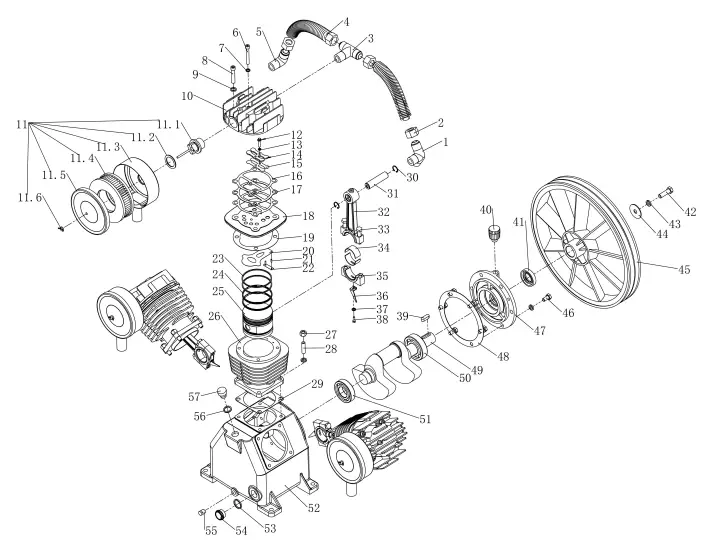
PARTS LIST-PUMP Model:W-0.67
| No. Q.ty | Part no. | Part Name |
| 1 | 4213412300000 | 3-way manifold nipple |
| 2 4 | 4690040000000 | Nut |
| 3 | 4213418300000 | 3-way manifold nipple |
| 4 2 | 4682021601000 | Copper tube,lnter discharge |
| 5 1 | 4213409200000 | Elbow fitting |
| 6 3 | 4608060000000 | Head bolt |
| 7 3 | 4660801000000 | Spring washer |
| 8 12 | 4601005000000 | Head,bolt |
| 9 30 | 4661000000000 | Spring washer |
| 10 3 | 8370067000000 | Cylinder head |
| 11 3 | 4341115001000 | Intake filter Ass’Y |
| 11.1 3 | 4341115001001 | Support,lntake filter |
| 11.2 3 | 4341115001002 | Seal,lntake filter |
| 1 1.3 3 | 4341115001003 | Filter case |
| 11.4 3 | 4341115001004 | Element |
| 11.5 3 | 4341115001005 | Filter cover |
| 11.6 3 | 4341115001006 | Nut.Butterfly |
| 12 6 | 4600501600000 | Screw |
| No. | Q.ty | Part no. | Part Name |
| 13 | 6 | 4660500000000 | Spring washer |
| 14 | 3 | 4290800000000 | Valve holder |
| 15 | 3 | 4170801000000 | Blade,valve |
| 16 | 6 | 4240901000000 | Gasket, Head |
| 17 | 3 | 4221080030000 | G asket, Head |
| 18 | 3 | 4160801000000 | Valve plate |
| 19 | 3 | 4222080010000 | G asket, valve |
| 20 | 3 | 4170800000000 | Blade,valve |
| 21 | 3 | 4140301000000 | Locking pin |
| 22 | 3 | 6030500000000 | Locking plate |
| 23 | 6 | 4110903000000 | Piston ring cco |
| 24 | 6 | 4110802000000 | Piston ring rof |
| 25 | 3 | 4100800000000 | Piston |
| 26 | 3 | 4150800000000 | Cylinder |
| 27 | 12 | 4611006000000 | Nut |
| 28 | 12 | 4200104000000 | Stud bolt |
| 29 | 3 | 4223080010000 | Cylinder gasket |
| 30 | 6 | 4630170300000 | Circlip |
| 31 | 3 | 4141707000000 | Piston pin |
| 32 | 3 | 4131716000000 | Conrod part 1 |
| 33 | 6 | 4601005000000 | Screw |
| 34 | 6 | 4190800000000 | Metal bearing |
| 35 | 3 | 4131716000000 | Conrod part 2 |
| 36 | 3 | 4290420000000 | Oil finger |
| 37 | 3 | 4660600000000 | Washer spring |
| 38 | 3 | 4600501500000 | Screw |
| 39 | 1 | 4641030000000 | Key |
| 40 | 1 | 1131615000000 | Air-Breather |
| 41 | 1 | 1123052100000 | Shaft seal |
| 42 | 1 | 4601203004000 | Screw |
| 43 | 1 | 4661200000000 | Spring washer |
| 44 | 1 | 4621234000000 | Plate washer |
| 45 | 1 | 4453708200000 | Flywheel |
| 46 | 6 | 4601003004000 | Screw |
| 47 | 1 | 8366067000000 | Front support |
| 48 | 1 | 4224080010000 | Gasket,Front support |
| 49 | 1 | 4180670000000 | Crankshaft |
| 50 | 1 | 4406306000000 | Bearing6306 |
| 51 | 1 | 4406306000000 | Bearing6306 |
| 52 | 1 | 8371067010000 | Crankcase |
| 53 | 1 | 4313400000000 | O-Ring |
| 54 | 1 | 4313400000000 | Oil sight glass |
| 55 | 4330140100000 | Plug Oil drain | |
| 56 | 1142025000000 | O-Ring | |
| 57 | 1142025000000 | Oil cap |
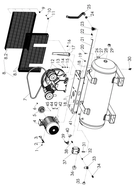
PARTS LIST-COMPRESSOR
Model: LB26200S3 V0.48
| No. | Q.ty | Part no. | Part Name | Remarks |
| 1 | 4600801604000 | Screw | ||
| 2 | 4660802000000 | Washer plate | ||
| 3 | 8221021000000 | Motor shake handshandle | ||
| 4 | 4910040313000 | Motor MEPS2 | ||
| 5 | 446B111000000 | Motor pulley | ||
| 6 | 4640830000000 | Key | ||
| 7 | 2 | 441B154900000 | V-Belt | |
| 8 | 3430480300000 | Belt guard | ||
| 8.1 | 3430480300001 | Belt guard ( FR) | ||
| 8.2 | 3430480300002 | Belt guard ( RR) | ||
| 9 | 10 | 3490040000000 | Belt guard clip | |
| 10 | 6 | 4600601206000 | Screw | |
| 11 | 6 | 3490030000000 | Belt guard washer | |
| 12 | 3500488890000 | Pump 0.48 | ||
| 13 | 4 | 4601004001000 | S crew | |
| 14 | 4 | 4661000000000 | Washer spring | |
| 15 | 4 | 4621028000000 | Washer plate | |
| 16 | 2 | 4600801604000 | Nut | |
| 17 | 3490003030000 | Bracket, Belt guard | ||
| 18 | 8110488900000 | Tank 200L | ||
| 18-1 | 8073009000000 | Base plate | ||
| 19 | 4 | 4611003000000 | Nut | |
| 20 | 4 | 4601003004000 | Screw | |
| 21 | 1 | 1220698000000 | Tube | |
| 22 | 4651806300000 | Nipple | ||
| 23 | 4730260000000 | Check valve | ||
| 24 | 2 | 4690040000000 | Lock nut | |
| 25 | 4682035000000 | Copper tube(Discharge) | ||
| 26 | 4 | 4621028000000 | Washer plate | |
| 27 | 4 | 4661000000000 | Washer spring | |
| 28 | 4 | 4611006000000 | Nut | |
| 29 | 2 | 4330320100000 | Plug.Socket head | |
| 30 | 4723800000000 | Drain valve | ||
| 31 | 4353814000000 | Nipple | ||
| 32 | 4351403000000 | Nipple | ||
| 33 | 4710020000000 | Pressure regulator | ||
| 34 | 4091250000000 | Quick coupler | ||
| 35 | 4302501404000 | Pressure gauge | ||
| 36 | 4302501403000 | Pressure gauge | ||
| 37 | 2002050900000 | Pressure switch MDR3 | ||
| 38 | 4701410000000 | Safety valve(AS) | ||
| 39 | 4740010000000 | Ball valve | ||
| 40 | 4290430000000 | Elbow | ||
| 41 | 4 | 4601004003000 | Screw | |
| 42 | 4 | 4621028000000 | Washer plate | |
| 43 | 4 | 4661000000000 | Washer spring | |
| 44 | 4 | 4611006000000 | Nut | |
| 45 | 4690220000000 | Set screw | ||
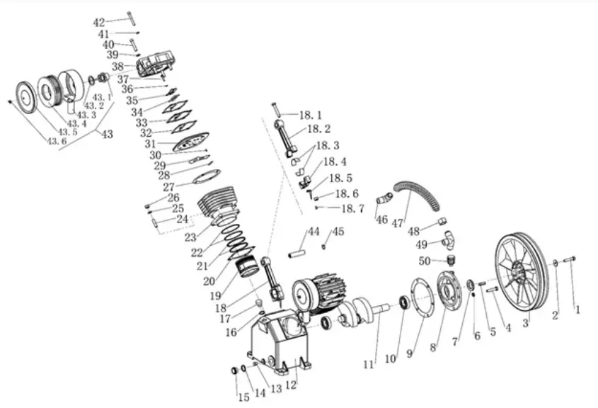
EXPLOSION VIEW-PUMP Model: V-0.48
PARTS LIST-PUMP Model: V-0.48
| No. | Q.ty | Part no. | Part Name | Remarks |
| 1 | 4600801604000 | Screw | ||
| 2 | 4660802000000 | Washer plate | ||
| 3 | 8221021000000 | Motor shake handshandle | ||
| 4 | 4910040313000 | Motor MEPS2 | ||
| 5 | 446B111000000 | Motor pulley | ||
| 6 | 4640830000000 | Key | ||
| 7 | 2 | 441B154900000 | V-Belt | |
| 8 | 3430480300000 | Belt guard | ||
| 8.1 | 3430480300001 | Belt guard ( FR) | ||
| 8.2 | 3430480300002 | Belt guard ( RR) | ||
| 9 | 10 | 3490040000000 | Belt guard clip | |
| 10 | 6 | 4600601206000 | Screw | |
| 11 | 6 | 3490030000000 | Belt guard washer | |
| 12 | 3500488890000 | Pump 0.48 | ||
| 13 | 4 | 4601004001000 | S crew | |
| 14 | 4 | 4661000000000 | Washer spring | |
| 15 | 4 | 4621028000000 | Washer plate | |
| 16 | 2 | 4600801604000 | Nut | |
| 17 | 3490003030000 | Bracket, Belt guard | ||
| 18 | 8110488900000 | Tank 200L | ||
| 18-1 | 8073009000000 | Base plate | ||
| 19 | 4 | 4611003000000 | Nut | |
| 20 | 4 | 4601003004000 | Screw | |
| 21 | 1 | 1220698000000 | Tube | |
| 22 | 4651806300000 | Nipple | ||
| 23 | 4730260000000 | Check valve | ||
| 24 | 2 | 4690040000000 | Lock nut | |
| 25 | 4682035000000 | Copper tube(Discharge) | ||
| 26 | 4 | 4621028000000 | Washer plate | |
| 27 | 4 | 4661000000000 | Washer spring | |
| 28 | 4 | 4611006000000 | Nut | |
| 29 | 2 | 4330320100000 | Plug.Socket head | |
| 30 | 4723800000000 | Drain valve | ||
| 31 | 4353814000000 | Nipple | ||
| 32 | 4351403000000 | Nipple | ||
| 33 | 4710020000000 | Pressure regulator | ||
| 34 | 4091250000000 | Quick coupler | ||
| 35 | 4302501404000 | Pressure gauge | ||
| 36 | 4302501403000 | Pressure gauge | ||
| 37 | 2002050900000 | Pressure switch MDR3 | ||
| 38 | 4701410000000 | Safety valve(AS) | ||
| 39 | 4740010000000 | Ball valve | ||
| 40 | 4290430000000 | Elbow | ||
| 41 | 4 | 4601004003000 | Screw | |
| 42 | 4 | 4621028000000 | Washer plate | |
| 43 | 4 | 4661000000000 | Washer spring | |
| 44 | 4 | 4611006000000 | Nut | |
| 45 | 4690220000000 | Set screw | ||
TROUBLESHOOTING
FAULT/ CAUSE/ REMEDY
- F) Pressure drop in tank.
- C) Air leaks at connections.
- R) Run the compressor to its maximum pressure. Switch it off and then brush a soapy water solution around all the connections, looking carefully to see if any bubbles appear. Tighten any connections where leaks appear. If the problem persists contact your dealer or authorised service agent.
- F) Air leaks from the underside of the pressure switch when the compressor is idle.
- C) Non-return valve seal is defective
- R) DRAIN ALL AIR FROM THE TANK!!! Remove the one-way valve plug. Clean the valve seat, nspect the seal and replace if necessary.
- F) Air leaks from the underside of the pressure switch when the compressor has been running for more than 1 minute.
- C) The pressure switch unload valve is faulty.
- R) Replace the pressure switch
- F) The compressor stopped and will not re-start
- C) Electric motor ehat relay (three phase) has tripped. Your compressor may be overworked.
- R) Turn the compressor off at the pressure switch. Let the motor cool down for at least 30 minutes. Turn the compressor on again at the pressure switch. If the compressor fails to restart, contact your dealer or authorised service agent.
- F) The compressor stopped and will not re-start
- C) Electric motor windings have been burnt out or damaged.
- R) Contact your dealer or authorised service agent.
- F) The compressor pump is not running at a constant speed.
- C) Pulley belt is slipping
- R) Re-tension the belt
- F) The compressor does not reach its maximum pressure, continually runs and overheats.
- C) Faulty head gasket or head valve or; C)compressor is under sized for application.
- R) Stop the compressor. Contact your dealer or authorised service agent.
- F) The compressor is noisy with knocking or has metallic clanging.
- C) Bearing or brush seizure.
- R) Stop the compressor immediately! Contact your dealer or authorised service agent.
- F) The compressor does not start.
- C) Mains Power. Faulty electrical Cables. Ambient temperature below 0° C. Low oil level.
- R) Check that all mains power connections are working and not damaged. Check that the compressor lead has not been damaged. If the ambient temperature is too low move the compressor to a warmer place. Check the oil level.
- F) Compressor runs continuously past the maximum pressure causing the safety valve to release C) Faulty pressure switch
- R) Contact your dealer or authorised service agent.
- F) The compressor safety valve releases below the compressors maximum pressure.
- C) Faulty safety valve.
- R) Do not attempt to adjust the safety valve from its factory setting. Contact your dealer or authorised service agent.
Important information for your Warranty: Commissioning Checklist lronair Three Phase Compressors
Dear Customer,
Congratulations on your purchase of a IRONAIR Industrial compressor. Your compressor comes with a three year tank, two year pump and one year electric motor and compressor components warranty. This warranty is valid from the date of sale and covers repair and or replacement of faulty materials and workmanship. To ensure your compressor is running correctly we recommend it is commissioned by a qualified service technician by checking each of the points listed below. This form must be completed to validate your warranty.
This form must be completed to validate your warranty.
Date Compressor Commissioned ______ (Serial No. ______ )
- Electric motor and pump running in correct direction.
- Pump oil level at correct level.
- Air lines not leaking.
- Correct electrical connection and suitable amperage. Suitable ambient working temperature.
- Correct cut out pressure
- Correct cut in pressure.
- Safety valve operating correctly
- Drainage valve operating correctly
- Installation angled to ensure fall to drain valve
- Clean air environment
- Capacity of compressor is suitable for usage
Important information for your Warranty: Commissioning Checklist lronair Three Phase Compressors
Dear Customer,
Congratulations on your purchase of a IRONAIR Industrial compressor. Your compressor comes with a three year tank, two year pump and one year electric motor and compressor components warranty. This warranty is valid from the date of sale and covers repair and or replacement of faulty materials and workmanship. To ensure your compressor is running correctly we recommend it is commissioned by a qualified service technician by checking each of the points listed below. This form must be completed to validate your warranty.
This form must be completed to validate your warranty.
Date Compressor Commissioned ______ (Serial No. ______ )
- Electric motor and pump running in correct direction.
- Pump oil level at correct level.
- Air lines not leaking.
- Correct electrical connection and suitable amperage.
- Suitable ambient working temperature.
- Correct cut out pressure
- Correct cut in pressure.
- Safety valve operating correctly
- Drainage valve operating correctly
- Installation angled to ensure fall to drain valve
- Clean air environment
- Capacity of compressor is suitable for usage
Signed: ______ _
Company name: ______ _


