
northerntool 200-2900 Electric Air Compressors
SPECIFICATION CHART
| SPECIFICATION CHART / TABLEAU DES SPÉCIFICATIONS / CUADRO DE ESPECIFICACIONES | |||||
|
MODEL NO. (MODÈLE) (MODELO) |
RUNNING H.P. (CV) | TANK CAPACITY GALLONS (CAPACITÉ DU RÉSERVOIR – LITRES) (CAPACIDAD DEL TANQUE – LITROS) | VOLTAGE/AMPS/ PHASE (TENSION/AMPS/ PHASE) (VOLTAJE/AMP/FASE) | KICK-IN PRESSURE (PRESSION D’OUVERTURE) (PRESION DE CONEXION) | KICK-OUT PRESSURE (PRESSION DE FERM.) (PRESION DE DESCONEXION) |
| L1682066.MN | 1.6 | 20 (75,7) | 120/240-15/7.5-1 | 105 (7,23 bar) | 135 (9,30 bar) |
| LC1682066.MN | 1.6 | 20 (75,7) | 120/240-15/7.5-1 | 105 (7,23 bar) | 135 (9,30 bar) |
WARNING:
Read and understand all safety precautions in this manual before operating. Failure to comply with
instructions in this manual could result in personal injury, property damage, and/or voiding of your warranty. The manufacturer WILL NOT be liable for any damage because of failure to follow these instructions.
SAFETY GUIDELINES
The following information relates to protecting YOUR SAFETY and PREVENTING EQUIPMENT PROBLEMS. To help you recognize this information, we use the following symbols. Please read the manual and pay attention to these sections.
- A POTENTIAL HAZA RD THAT WILL CAUSE SERIOUS INJURY OR LOSS OF LIFE.
- A POTENTIAL HAZARD THAT COULD CAUSE SERIOUS INJURY OR LOSS OF LIFE.
- A POTENTIAL HAZARD THAT MAY CAUSE MODERATE INJURY OR DAMAGE TO EQUIPMENT
IMPORTANT SAFETY INSTRUCTIONS
- Never spray flammable liquids in a confined area. It is normal for the motor and pressure switch to produce sparks while operating. If sparks come into contact with vapors from gasoline or other solvents, they may ignite, causing fire or explosion. Always operate the compressor in a well–ventilated area. Do not smoke while spraying. Do not spray where sparks or flame are present. Keep compressor as far from spray area as possible. Store flammable materials in a secure location away from compressor. Equip the area of operation with a fire extinguisher.
- Do not weld, drill or modify the air tank of this compressor. Welding or modifications on the air compressor tank can severely impair tank strength and cause an extremely hazardous condition. Welding or modifying the tank in any manner will void the warranty. If tank develops a leak, replace it immediately with a new tank or replace the entire compressor.
- Never use an electric air compressor outdoors when it is raining or on a wet surface, as it may cause an electric shock. Failure to provide adequate grounding to this product could result in serious injury or death from electrocution. Make certain that the electrical circuit to which the compressor is connected provides proper electrical grounding, correct voltage and adequate fuse protection.
- This unit starts automatically. ALWAYS shut off the compressor, remove the plug from the outlet, and bleed all pressure from the system before servicing the compressor, and when the compressor is not in use. Do not use the unit with the shrouds or belt guard removed. Serious injury could occur from contact with moving parts. Stay alert and watch what you are doing when operating the compressor. Do not use the compressor while tired or under the influence of drugs or alcohol.
- Check the manufacturer’s maximum pressure rating for air tools and accessories. Compressor outlet pressure must be regulated so as to never exceed the maximum pressure rating of the tool. Relieve all pressure through the hose before attaching or removing accessories. Never use compressor to inflate small low pressure objects such as children’s toys, footballs, basketballs, etc.
- High temperatures are generated by the pump and manifold. To prevent burns or other injuries, DO NOT touch the pump, manifold or transfer tube while the pump is running. Allow them to cool before handling or servicing. Keep children away from the compressor at all times. Do not reach around protective shrouds or attempt to maintenance until unit has been allowed to cool.
- Always wear MSHA/NIOSH approved, properly fitting face mask or respirator and work in a well ventilated area when using tools that generate dust. Some dust created by power sanding, grinding, drilling and other construction activities contains chemicals known (to the State of California) to cause cancer, birth defects or other reproductive harm. Some examples of these chemicals are:
- lead from lead-based paints
- crystalline silica from bricks and cement and other masonry products
- arsenic and chromium from chemically treated lumber.
- Be certain to read all labels when you are spraying paints or toxic materials, and follow the safety instructions provided on the lable or safety sheets for the materials you are spraying. Use a MSHA/NIOSH approved respirator mask if there is a chance of inhaling anything you are spraying. Read all instructions and be sure that your respirator mask will protect you. Work in an area with good cross ventilation.
- Always wear ANSI Z87.1 approved safety goggles when using an air compressor. Never point any nozzle or sprayer toward a person, animal or any part of the body. Equipment can cause serious injury if the spray penetrates the skin.
- Do not adjust the pressure relief valve for any reason. Doing so voids all warranties. The relief valve has been pre-set at the factory for the maximum pressure of this unit. Personal injury and /or property damage may result if the relief valve is tampered with.
- Do not use plastic or pvc pipe for compressed air. Use only galvanized steel pipe and fittings for compressed air distribution lines.
- Unattended operation of this compressor could result in personal injury or property damage. To reduce the risk of fire, do not allow the compressor to operate unattended. Always disconnect electrical power by turning the pressure switch to off and drain the tank daily or after each use.
- Air obtained directly from the compressor should never be used to supply air for human consumption. The air stream may contain carbon monoxide, toxic vapors, or solid particles from tank. Breathing these contaminant’s can cause serious injury or death. In order to use air produced by this compressor for breathing, suitable filters and in-line safety equipment must be properly installed. In-line filters and safety equipment must be properly installed.
- In-line filters and safety equipment used in conjunction with the compressor must be capable of treating air to all applicable local and federal codes prior to human consumption.
- Always operate the compressor in a stable secure position to prevend accidental movement of the unit. Never operate the compressor on a table, workbench, roof or other elevated position. Use additional air hose to reach high locations.
- Always wear hearing protection when using an air compressor. Failure to do so may result in hearing loss.
- Refer to the air compressor’s serial label for the unit’s voltage and amperage requirements. Ensure that all wiring is done by a licensed electrician, in accordance with the National Electrical code.
- WARNING: CONTAINS LEAD.
May be harmful if eaten or chewed. May generate dust containing lead. Wash hands after use. Keep out of reach of children. - WARNING:
This product can expose you to chemicals including Lead, which is known to the State of California to cause cancer and birth defects or other reproductive harm. For more information go to www.P65Warnings. ca.gov.
CAUTION:
Drain the moisture from the tank on a daily basis. A clean, dry tank will help prevent corrosion.Pull the tank safety valve ring daily to ensure that the valve is functioning properly, and to clear the valve of any possible obstructions.To provide proper ventilation for cooling, the compressor must be kept a minimum of 12 inches (31 cm) from the nearest wall, in a well–ventilated area. Restricting any of the compressor ventilation openings will cause overheating and could cause fire, never place objects against or on top of compressor.Fasten the compressor down securely if transporting is necessary. Pressure must be released from the tank before transporting.Protect the air hose and electric cord from damage and puncture. Inspect them weekly for weak or worn spots, and replace if necessary.To reduce the risk of electric shock, do not expose to rain. Store indoors.To reduce the risk of electric shock, do not expose to rain. Store indoors.
GLOSSARY OF TERMS
- CFM: Cubic feet per minute; a unit of measure of air flow.
- PSI: Pounds per square inch; a unit of measure of air pressure.
- Cut-in pressure: While the motor is off, air tank pressure drops as you continue to use your accessory. When the tank pressure drops to factory set low pressure point, the motor will restart automatically. The low pressure at which the motor automatically restarts is called “cut-in” pressure.
- Cut-out pressure: When an air compressor is turned on and begins to run, air pressure in the air tank begins to build. It builds to the factory set high pressure point before the motor automatically shuts off, protecting your air tank from pressure higher than its capacity. The high pressure at which the motor shuts off is called “cut-out” pressure.
- Well-ventilated: Means of providing fresh air in exchange for dangerous exhaust or vapors.
- Dedicated circuit: An electrical circuit reserved for the exclusive use of the air compressor.
OVERVIEW
BASIC AIR COMPRESSOR COMPONENTS
The basic components of the air compressor are the electric motor, pump, pressure switch and tank (see Fig. 1).The electric motor (see A) powers the pump. The electric motor is equipped with an overload protector to help prevent possible motor burnout. If the motor becomes overheated, the overload protector will shut it down. Should this occur, allow the motor to cool for 10-15 minutes, then press (never force) the motor reset switch to restart the motor. The pump (see B) compresses the air and discharges it into the The tank (see C) stores the compressed air. The pressure switch (see D) shuts down the motor and relieves air pressure in the pump and transfer tube when the air pressure in the tank reaches the kick–out pressure. As compressed air is used and the pressure level in the tank drops to the kick–in pressure, the pressure switch restarts the motor automatically, without warning and the pump resumes compresasing air. The air line outlet (see E). Connect 1/4” NPT air hose to this outlet.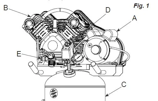
ASSEMBLY
This compressor was shipped with oil in the pump crankcase. Check oil before operating the air compressor, see Check Oil under Maintenance.
- Unpack the air compressor. Inspect the unit for damage. If the unit has been damaged in transit, contact the carrier and complete a damage claim. Do this immediately because there are time limitations to damage claims.
- carton should contain:
- air compressor
- operator/parts manual
- Check the compressor’s serial label to ensure that you have received the model ordered, and that it has the required pressure rating for its intended use.
- Locate the compressor according to the following guidelines:
- Position the compressor near a grounded electrical outlet (see GROUNDING INSTRUCTIONS). Avoid using an extension cord; use a longer hose instead.
- The flywheel side of the compressor must be at least 12 inches (31 cm) from any wall or obstruction, in a clean, well-ventilated area, to ensure sufficient air flow and cooling.
- In cold climates, store portable compressors in a heated building when not in use. This will reduce problems with lubrication, motor starting and freezing of water condensation.
- The compressor must be level to ensure proper lubrication of the pump and good drainage of the moisture in the tank.
- Connect an air hose (not included) to the manifold outlet.
COMPRESSOR CONTROLS
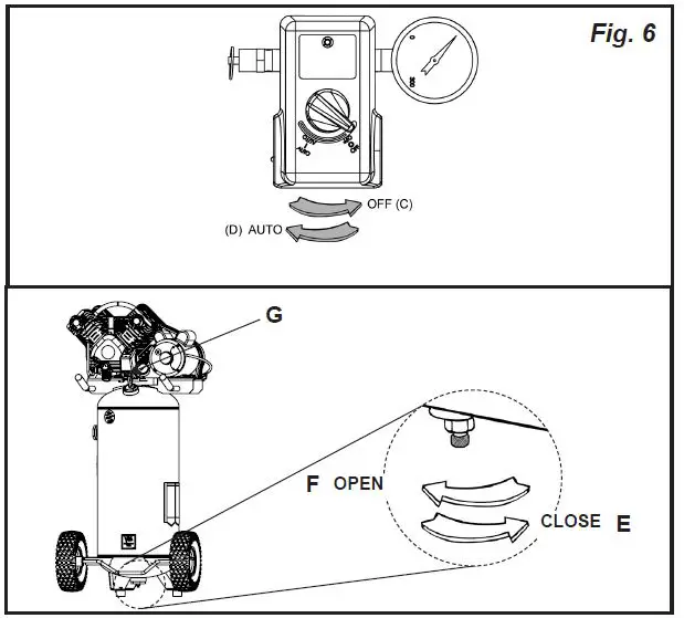
Pressure Switch (see A)
This switch turns on the compressor. It is operated manually, but when in the AUTO position, it allows the compressor to start up or shut down automatically, without warning, upon air demand. ALWAYS set this switch to OFF when the compressor is not being used, and before unplugging the compressor.
Tank Safety Valve (see B)
Used to allow tank pressure to escape into the atmosphere. If the pressure switch does not shut off the compressor at it’s “cut-out” pressure setting, the safety valve will protect against high pressure by releasing tank pressure at it’s factory set pressure (slightly higher than the pressure switch “cut-out” setting). To operate manually, pull the ring on the valve to relieve air pressure in the tank.
Pressure Release Valve (see C)
The pressure release valve (located on the bottom of the pressure switch), is designed to release compressed air from the compressor head and outlet tube when the compressor reaches “cut-out” or is shut off. The pressure valve allows the motor to restart freely. When the motor stops running, air will be heard escaping from this valve for a few seconds. No air should be heard leaking when the motor is running or after brief release after reaching “cut-out” pressure.
Tank Pressure Gauge (see D)
This gauge measures the pressure level of the air stored in the tank. It is not adjustable by the operator, and does not indicate line pressure.
Air Pressure Regulator (see E)
This air pressure regulator enables you to adjust line pressure to the tool you are using.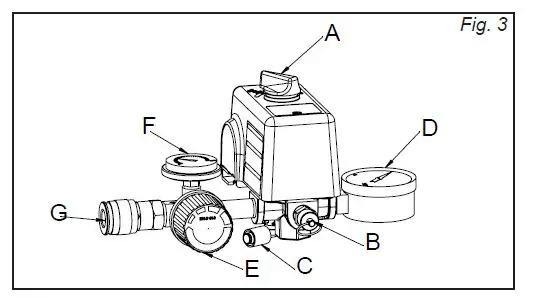
MOTOR RESET AND WARNING
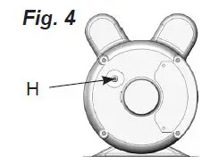
If the motor shuts down because of overload, wait 10–15 minutes so the motor can cool down, then press (NEVER force) the reset switch (see H) to restart the motor.
NOTE:
Some models are equipped with a dual voltage motor 120/240 volt. Most models are factory wired for 120 volt operation. If conversion from 120 volt to 240 volt is required, refer to the motor nameplate and have the conversion completed by a Licensed Electrician.
ELECTRICAL WIRING
Refer to the air compressor’s serial label for the unit’s voltage and amperage requirements.
Use a dedicated circuit
For best performance and reliable starting, the air compressor must be plugged into a dedicated circuit, as close as possible to the fuse box or circuit breaker. The compressor will use the full capacity of a typical 15 amp household circuit. If any other electrical devices are drawing from the compressor’s circuit, the compressor may fail to start. Low voltage or an overloaded circuit can result in sluggish starting that causes the motor overload protection system or circuit breaker to trip, especially in cold conditions.
NOTE:
To handle the initial electrical load of starting the air compressor, a circuit breaker is recommended. If the air compressor is connected to a circuit protected by a fuse, use dual element time delay fuses (Buss Fusetron type “T” only).
EXTENSION CORDS
NOTE:
Avoid use of extension cords. For optimum performance, plug the compressor power cord directly into a grounded wall socket. Do not use an extension cord unless absolutely necessary. Instead, use a longer air hose to reach the area where the air is needed.If use of an extension cord cannot be avoided, the cord should be no longer than 50 feet and be a minimum wire size of 12 gauge (AWG). Do not use a 16 or 14 gauge extension cord. Use only a 3-wire extension cord that has a 3-blade grounding plug, and a 3-slot receptacle that will accept the plug on the product. Make sure your extension cord is in good condition. An undersized cord will cause a drop in line voltage, resulting in loss of power and overheating. The smaller the gauge number, the heavier the cord.
GROUNDING INSTRUCTIONS
This product should be grounded. In the event of an electrical short circuit, grounding reduces the risk of electric shock by providing an escape wire for the electric current.
ELECTRICAL POWER REQUIREMENTS

This product is equipped with a cord having a grounding wire with an appropriate grounding plug. The plug must be plugged into an outlet that is properly installed and grounded in accordance with all local codes and ordinance. grounding plug can result in a risk of electric shock. If repair or replacement of the cord or plug is necessary, do not connect the grounding wire to either flat blade terminal of the plug. The wire ` insulation having an outer surface that is green with or without yellow stripes is the grounding wire.This product is for use on a 120 volt circuit. A cord with a grounding plug, as shown here, shall be used.Make sure that the product is connected to an outlet having the same configuration as the plug (see Fig. 5). No adapter should be used with this product.Check with a licensed electrician if the grounding instructions are not completely understood, or if in doubt as to whether the product is properly grounded. Do not modify the plug provided; if it will not fit the outlet, have the proper outlet installed by a licensed electrician.
OPERATING INSTRUCTIONS
- Check the oil level in the pump (see “Checking the Oil” in the maintenance section).
- Turn the pressure switch to the OFF position (see C).
- Open the petcock (see F).
- Plug in the power cord. Turn the pressure switch to the AUTO position (see D). The motor should start. Allow the compressor to run for 30 minutes, to break in the internal parts.
- After about 30 minutes, turn the pressure switch to the OFF position (see C).
- Close the petcock (see E). Turn in the clockwise direction.
- Turn the pressure switch to the AUTO position. The compressor will start and fill the tank to the cut-out pressure and stop.
DAILY START-UP
- Check the oil level in the pump (see “Checking the Oil” in the maintenance section).
- Turn the pressure switch to the OFF position (see C).
- Close the tank petcock (see E). Turn in the clockwise direction.
- Plug in the power cord.
- Turn the pressure switch to the AUTO position (see D). The pump will start filling the tank with air. When the air pressure in the tank reaches the level preset at the factory, the pressure switch will turn off the electric motor. As air is used and the pressure level in the tank drops, the pressure switch will start the motor and the pump will begin refilling the tank.
WARNING:
High temperatures are generated by the pump. To prevent burns or other injuries, DO NOT touch the pump or transfer tube while the pump is running. Allow it to cool before handling or servicing. Keep children away from the compressor at all times.automatically. ALWAYS shut off the compressor, remove the plug from the outlet, and bleed all pressure from the system before servicing the compressor, and when the compressor is not in use. Do not use the unit with the shrouds or belt guard removed. Serious injury could occur from contact with moving parts. Regular maintenance will ensure trouble–free operation. Your electric powered air compressor represents high–quality engineering and construction; however, even high–quality machinery requires periodic maintenance. The items listed below should be inspected on a regular basis.
SHUTDOWN
- Turn the pressure switch to the OFF position (see C).
- Unplug the power cord.
- Reduce pressure in the tank through the outlet hose. You can also pull the relief valve ring (see G) and keep it open to relieve pressure in the tank.
- Open the petcock (see F) to allow moisture to drain from the tank.

MAINTENANCE
RISK OF INJURY. This unit starts automatically. ALWAYS shut off the compressor, remove the plug from the outlet, and bleed all pressure from the system before servicing the compressor, and when the compressor is not in use. Do not use the unit with the shrouds or belt guard removed. Serious injury could occur from contact with moving parts.Regular maintenance will ensure trouble–free operation. Your electric-powered air compressor represents high–quality engineering and construction; however, even high–quality machinery requires periodic maintenance. The items listed below should be inspected on a regular basis.Drain the moisture from the tank (for instructions, see “Shutdown” in the operating instructions section).In cold climates, drain the tank after each use to reduce problems with freezing of water condensation.Check the level of oil in the pump with the sight glass. The pump oil level must be between A and B. Do not overfill or underfill.
CHANGING THE OIL
Remove the oil plug (C) and drain the oil until it slows to a drip, then close. Unscrew the oil fill plug (E) and add compressor oil (approx. 11.35 oz.) until it is between full (A) and add (B). Replace the oil fill plug. Never overfill or under fill the pump.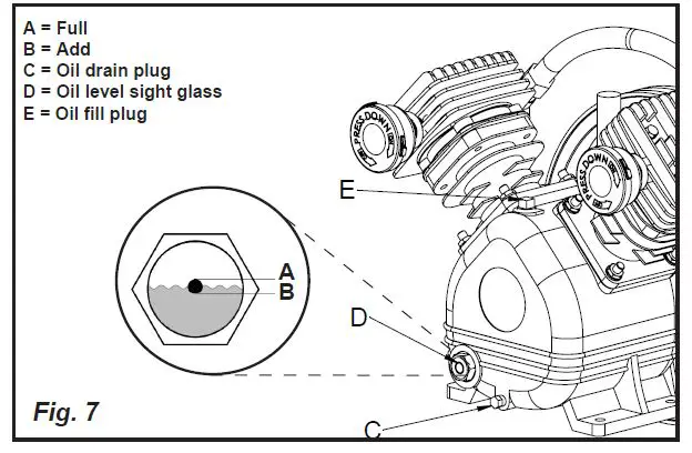
DRIVE BELT TENSION ADJUSTMENT
NOTE:
Drive belt tensioning and pulley alignment are done at the same time. They are discussed separately for clarity.automatically. ALWAYS shut off the compressor, remove the plug from the outlet, and bleed all pressure from the system before servicing the compressor, and when the compressor is not in use. Do not use the unit with the shrouds or belt guard removed. Serious injury could occur from contact with moving parts.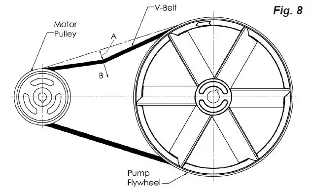
Proper belt tension and pulley alignment must be maintained for maximum drive efficiency and belt life. The correct tension exists if a deflection (see A) of 1/2” (13 mm) occurs by placing 5 lbs. (2.3 kg) of force (see B) midway between the motor pulley and the pump flywheel (See Fig. 8). This deflection can be adjusted by the following procedure. The pulley should be carefully aligned with the flywheel, and all setscrews.
- Remove the belt guard.
- Loosen the motor mounting bolts.
- Shift the motor to the point where the correct deflection exists (A & B).
- Retighten the motor mounting bolts to 130-180 in.-lbs.
- Check to ensure that the tension remained correct.
- Reinstall the belt guard. All moving parts must be guarded.
PULLEY ALIGNMENT
NOTE:
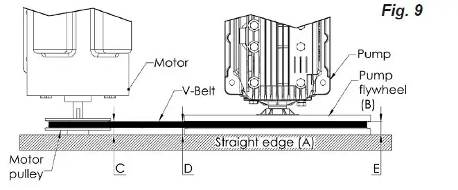
Drive belt tensioning and pulley alignment are done at the same time. They are discussed separately for clarity. automatically. ALWAYS shut off the compressor, remove the plug from the outlet, and bleed all pressure from the system before servicing the compressor, and when the compressor is not in use. Do not use the unit with the shrouds or belt guard removed. Serious injury could occur from contact with moving parts.To check pulley alignment, remove the belt guard and place a straightedge (see A) against the pump flywheel (see B) (See Fig. 9). Measure and record the distance from the straightedge to the edge of the drive belt at point C. Then measure the distance from the straightedge to the edge of the drive belt again at points D and E. Both distances should be the same as at point C. If D or E are different from C, there is a misalignment which must be corrected before the compressor is run. To correct a pulley misalignment, use the following procedure.
- Remove the belt guard.
- Loosen the motor mounting bolts.
- Align the motor pulley with the pump flywheel (C-D-E must be equal ).
- Adjust the proper belt tension.
- Retighten the motor mounting bolts to 130-180 in.-lbs.
- Reinstall the belt guard. All moving parts must be guarded.

DRIVE BELT REPLACEMENT
- Remove the belt guard.
- Loosen the motor mounting bolts.
- Shift the motor towards the pump to the point where the belts can be easily removed and installed.
- Remove and replace belts. NOTE: The belts must be centered over the grooves on the flywheel and motor pulley.
- Shift the motor back to the point where the correct deflection exists (see “Drive Belt Tension Adjustment”).
- Retighten the motor mounting bolts to 130-180 in.-lbs.
- Check to ensure that the tension remained correct.
- Reinstall the belt guard. All moving parts must be guarded.
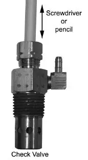
TO REPLACE OR CLEAN CHECK VALVE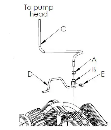
- Turn air compressor off, remove the power cord from the outlet or lock out the power supply and relieve all the air pressure from the tank (refer to “Shutdown” in Operating Instructions).
- Make sure the compressor has cooled down before servicing. Using the appropriately sized wrench, loosen the compression nut (A) on the check valve (B). Gently move the transfer tube
- valve disc up and down. If the valve disc does not move freely up and down, the check valve needs to be cleaned or replaced.

- Clean the check valve with warm soapy water and make sure to dry thoroughly before reinstalling. If the disc valve still does not move freely up and down, it will need to be replaced.
- Apply thread sealant to the check valve threads and reinstall into the tank by turning clockwise. Make sure it is the same orientation as when it was removed.
- Replace the bleeder tube by pushing it back onto the barbed fitting of the elbow.
- Replace the transfer tube and tighten compression nut.
CLEANING THE AIR FILTERS
A dirty air filter will reduce the compressor’s performance and life. To avoid any internal contamination of the A B pump, the filters should be cleaned frequently, and replaced on a regular basis. Felt filters should be cleaned in warm, soapy water, rinsed, and allowed to air dry before reinstallation. Paper filters should be replaced when dirty. Do not allow the filters to become filled with dirt or paint. If the filter becomes filled with paint, it should be replaced. Direct exposure to dirty conditions or painting areas will void your warranty.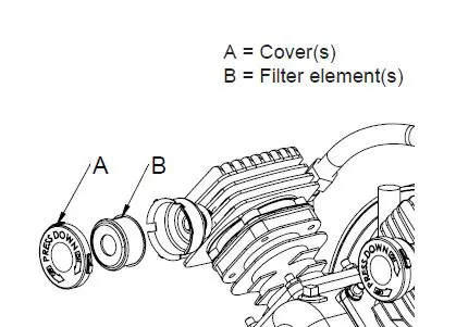
Check that all connections are tight. A small leak in any of the hoses, transfer tubes, or pipe connections will substantially reduce the performance of your air compressor. If you suspect a leak, spray a small amount of soapy water around the area of the suspected leak with a spray bottle. If bubbles appear, repair or replace the faulty component. Do not over tighten any connections.Before storing the compressor for a prolonged period, use an air blow gun to clean all dust and debris from the compressor. Disconnect the power cord and coil it up. Pull the tank safety valve to release all pressure from the tank. Drain all moisture from the tank. Clean the filter elements and filter housings; replace the elements if necessary. Drain the oil from the pump crankcase and replace it with new oil. Cover the entire unit to protect it from moisture and dust.
SERVICE INTERVAL
|
Perform the following maintenance at the intervals indicated below. | Daily or after each use | Every 100 operating hours | After first 8 hours and then every 100 operating hours |
| Inspect air filters (clean or replace as necessary) | • | ||
| Check pump oil level | • | ||
| Change pump oil (Use full synthetic, non-detergent air compressor oil.) | • | ||
| Operate the tank safety valve | • | ||
| Check belt tension | • | ||
| Drain tank | • | ||
| Check and tighten all bolts (do not over tighten) | • |
TROUBLESHOOTING
| PROBLEM | POSSIBLE CAUSE | SOLUTION |
| Excessive current draw trips circuit breaker or motor reset switch | Low voltage/motor overload | Check that power supply is adequate and that compressor is on a dedicated circuit. |
| Drive belt tension too tight | Readjust belt tension. | |
| Restricted air passages | Inspect and replace transfer tubes or the check valve, (see “To replace or clean check valve” in the maintenance section). | |
| Compressor stalls | Low voltage to motor | Furnish adequate power. |
| Bad check valve | Replace the check valve (see “To replace or clean check valve” in the maintenance section). | |
| Seized pump | Contact a qualified service center. | |
| Low discharge pressure | Air leaks | Tighten or replace leaking fittings or connections. Do not overtighten. |
| Leaking valves | Contact a qualified service center. | |
| Restricted air intake | Clean or replace air filter element(s). | |
| Blown gaskets | Contact a qualified service center. | |
| Worn piston rings or cylinder | Contact a qualified service center. | |
| Compressor pump knocking | Loose motor pulley or pump flywheel | Retighten pulley and flywheel. Check alignment. |
| Low oil level in pump crankcase | Keep oil at proper level at all times. | |
| Excess carbon on valves or top of piston | Contact a qualified service center. | |
| Oil in discharge air | Worn piston rings or cylinder | Contact a qualified service center. |
| Restricted air intake | Clean or replace the air filter element(s). | |
| Oil level too high | Reduce to proper level. | |
| Overheating | Poor ventilation | Relocate compressor to an area with cool, dry, well circulated air, at least 12 in. from nearest wall. |
| Dirty cooling surfaces | Clean all cooling surfaces thoroughly. | |
| Restricted air passages | Inspect and replace transfer tubes or the check valve, (see “To replace or clean check valve” in the maintenance section). | |
| Excessive belt wear | Pulley out of alignment | Realign pulley with compressor flywheel. |
| Improper belt tension | Readjust. | |
| Pulley wobbles | Replace the pulley and check for a damaged crankshaft or flywheel. | |
| Compressor won’t start in cold temperatures | Too much back pressure in tank | Open petcock when starting motor. |
| 40W oil in crankcase | Use full synthetic, non-detergent air compressor oil. | |
| Compressor too cold | Move compressor to a warmer location. | |
| Air leaking through bleeder valve after compressor shuts off | Dirty or defective check valve. | Replace or clean the check valve (see “To replace or clean check valve” in the maintenance section). |
PARTS DRAWING / DESSIN DES PIÈCES / ESQUEMA DE LAS PIEZAS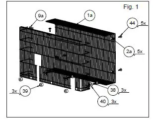
| Item Article Artículo | Part No No / P Núm / P | Qty Qté Cant |
Description |
Descripción |
Descripción | ||||
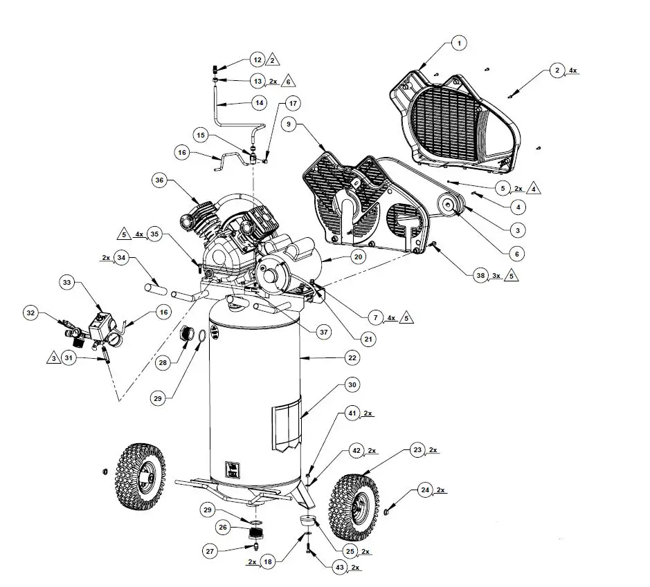
| 1 | 125-0208 | 1 | Beltguard, outer | Garant | Protector | ||||
| or 1a (Fig. 1) | 125-0175 | 1 | Beltguard, outer, wire | Garant | Protector | ||||
| 2 | 061-0152 | 6 | Screw, #10-14 X 3/4” | Vis | Tornillo | ||||
| or 2a (Fig. 1) | 103-0205 | 5 | Fastener | Attache | Sujetador | ||||
| 3 | 007-0010 | 1 | V-Belt, 4L-460 | Courroie | Correa | ||||
| 4 | 146-0016 | 1 | Key | Clé | Chaveta | ||||
| 5 | 061-0238 | 2 | Setscrew, 5/16”-18 x 3/8” | Vis d’arrêt | Tornillo fajador | ||||
| 6 | 006-0174 | 1 | Pulley | Poulie | Polea | ||||
| 7 | 059-0012 | 4 | Bolt, 5/16 x 1/2 | Boulon | Perno | ||||
| 9 | 125-0207 | 1 | Beltguard, inner | Garant | Protector | ||||
| or 9a (Fig. 1) | 125-0174 | 1 | Beltguard, inner, wire | Garant | Protector | ||||
| 12 | 068-0092 | 1 | Connector | Connecteur | Conector | ||||
| 13 | 058-0007 | 2 | Nut, 3/8” O.D. tube | Écrou | Tuerca | ||||
| 14 | 145-0478 | 1 | Tube, transfer | Tube | Tubo | ||||
| 15 | 031-0037 | 1 | Check Valve, 1/2” x 3/8” | Soupape | Válvula | ||||
| 16 | 145-0324 | 1 | Tube, bleeder 1/4” x 28” | Tube | Tubo | ||||
| 17 | 064-0056 | 1 | Elbow, 90° brass | Coude | Codo | ||||
| 18 | 060-0202 | 2 | Washer, 5/16” ID x 1” OD | Rondelle | Arandela | ||||
| 20 | 160-0345 | 1 | Motor (BTM56RB34D1.8M) (See capacitor table below) | Moteur (BTM56RB34D1.8M) (voir le tableau de condensateur ci-dessous) | Motor (BTM56RB34D1.8M) (vea la tabla del condensador abajo) | ||||
| or | 160-0354 | 1 | Motor (56S34D1.8M) (See capacitor table below) | Moteur (56S34D1.8M) (voir le tableau de condensateur ci-dessous) | Motor (56S34D1.8M) (vea la tabla del condensador abajo) | ||||
| or | 160-0360 | 1 | Motor (5KCR160DXP0023Y) (See capacitor table below) | Moteur (5KCR160DXP0023Y) (voir le tableau de condensateur ci-dessous) | Motor (5KCR160DXP0023Y) (vea la tabla del condensador abajo) | ||||
| or | 160-0355 | 1 | Motor (56S34D2M) (See capacitor table below) | Moteur (56S34D2M) (voir le tableau de condensateur ci-dessous) | Motor (56S34D2M) (vea la tabla del condensador abajo) | ||||
| 21 | 026-0233 | 1 | Cord, interconnect | Câble | Cordón | ||||
| 22 | 153-0165 | 1 | Tank assembly (includes items 23-30) | Ensemble du réservoir (inclut les articles 23-30) | Conjunto de tanque (incluye los artículos 23-30) | ||||
| 23 | 095-0081 | 2 | Wheel, pneumatic 10” | Roue | Rueda | ||||
| 24 | 033-0001 | 2 | Hubcap 1/2” | Chapeau de moyeu | Tapacubo | ||||
| 25 | 094-0186 | 2 | Pad | Tampon | Almohadilla | ||||
| 26 | 512-0035 | 1 | Bushing, 1-1/2 NPSM x 1/4 NPT | Bague | Buje | ||||
| 27 | 072-0006 | 1 | Petcock | Robinet de purge | Llave de desagüe | ||||
| 28 | 512-0039 | 1 | Pipe plug, 1-1/2 NPSM | Bouchon | Tapò | ||||
| 29 | 513-0002 | 2 | O-Ring 1-1/2 | Joint torique | Anillo tórico | ||||
| 30 | 098-3870 | 1 | Label, warning | D’avertissement étiquette | Etiqueta de advertencia | ||||
| 31 | 065-0005 | 1 | Nipple, 1/4” x 2-1/2” | Manchon fileté | Niple | ||||
| 32 | 026-0030 | 1 | Cord, power | Câble | Cordón | ||||
| 33 | See page 14 | 1 | Manifold assembly | Ensemble du collecteur | Conjunto de múltiple | ||||
| 34 | 093-0031 | 2 | Handle grip | Poignée | Empuñadura | ||||
| 35 | 059-0009 | 4 | Bolt, 5/16 x 1” | Boulon | Perno | ||||
| 36 | See pages 12-13 | 1 | Pump assembly | Ensemble du pompe | Conjunto de bomba | ||||
| 37 | 098-2856 | 1 | Label, warning | D’avertissement étiquette | Etiqueta de advertencia | ||||
| 38 | 059-0410 | 3 | Bolt, 5/16-18 x 1.25 | Boulon | Perno | ||||
| 39 | 060-0217 | 3 | Spacer | Spacer | Spacer | ||||
| 40 | 060-0023 | 3 | Washer, 3/8 | Rondelle | Arandela | ||||
| 41 | 058-0129 | 2 | Nut, 5/16 | Écrou | Tuerca | ||||
| 42 | 060-0156 | 2 | Washer, 5/16 | Rondelle | Arandela | ||||
| 43 | 059-0010 | 2 | Bolt, 5/16 x 1.25 | Boulon | Perno | ||||
| 44 | 061-0255 | 5 | Screw, M5 x 20mm | Vis | Tornillo | ||||
| CAPACITORS / CONDENSATEURS / CONDENSADORES | |||||||||
| Start capacitor Le condensateur de démarrage La condensador de arranque | Start capacitor cover Le couvercle de démarrage du condensador La tapa de arranque la condensador | Run capacitor Le condensateur de march La condensador de funcionar | Run capacitor cover Le couvercle de marche du condensateur La tapa de funcionar la condensador | ||||||
| Better motor 160-0345 | 166-0198 (BT198K18- 166-0198) | 166-0200 (BT198K18- 166-0200) | 166-0199 (BT198K18- 166-0199) | 166-0200 (BT198K18- 166-0200) | |||||
| Zhengli motor 160-0354 | 166-0208 (2901) | 166-0210 (1401) | 166-0209 (1501) | 166-0210 (1401) | |||||
| Marathon motor 160-0360 | 166-0215 (81.409.1.18) | 166-0217 (81.14.1.16) | 166-0216 (81.409.2.112) | 166-0217 (81.14.1.16) | |||||
PARTS DRAWING / DESSIN DES PIÈCES / ESQUEMA DE LAS PIEZAS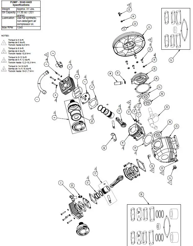
| PARTS LIST / LISTE DE PIÈCES / LISTA DE LA PIEZAS | |||||
| Item Article Artículo | Part No No / P Núm / P | Qty Qté Cant |
Description |
Description |
Descripción |
| 1 | 145-0486 | 1 | Tube, with compression nuts | Tube | Tubo |
| 2 | 065-0107 | 1 | Elbow | Coude | Codo |
| 3 | 061-0239 | 8 | Socket head cap screw, M6 x 40mm | Vis | Tornillo |
| 4 | 060-0224 | 8 | Washer, M6 | Rondelle | Arandela |
| 5 | 042-0121 | 2 | Head, cylinder | Tête | Cabezal |
| 6 | 046-0302 | 2 | Gasket, cylinder head | Gasket, head | Joint, tête Empaquetadura, cabezal |
| 7 | 043-0207 | 2 | Valve plate assy (includes items 6 & 8) | Ensemble du plaque (inclut les articles 6 et 8) | Conjunto de placa (incluye los artículos 6 y 8) |
| 8 | 046-0303 | 2 | Gasket, cylinder | Joint, cylindre | Empaquetadura, cilindro |
| 9 | 019-0305 | 2 | Filter assembly (includes item 9A) | Filter (inclut les article 9A) | Filtro (incluye los artículo 9A) |
| 9A | 019-0328 | 2 | Filter element | Élément filtrant | Elemento filtrante |
| 10 | 054-0250 | 2 | Ring Set | Jeu d’anneaux | Juego de anillos |
| 11 | 069-0028 | 1 | Tee fitting | Pièce en t | Te |
| 12 | 048-0121 | 2 | Piston assembly | Ensemble du piston | Conjunto de pistón |
| 13 | 047-0099 | 2 | Rod | Tige | Varilla |
| 14 | 050-0065 | 2 | Cylinder | Cylindre | Cilindro |
| 15 | 058-0188 | 8 | Nut, Hex M8 | Écrou | Tuerca |
| 16 | 060-0222 | 13 | Lock washer, M8 | Rondelle | Arandela |
| 17 | 059-0420 | 7 | Stud bolt, M8 x 22 | Boulon de goujon | Perno del perno prisionero |
| 17a | 059-0460 | 1 | Stud bolt, M8 x 35 | Boulon de goujon | Perno del perno prisionero |
| 18 | 046-0304 | 2 | Gasket, crankcase | Joint, carter | Empaquetadura, cárter |
| 19 | 060-0195 | 1 | Washer, breather | Rondelle | Arandela |
| 20 | 056-0078 | 1 | Oil fill plug | Bouchon | Tapón |
| 21 | 032-0126 | 1 | Oil sight glass w/o-ring | Verre de vue de niveau d’huile | Cristal de la vista del nivel de aceite |
| 22 | 062-0066 | 1 | Oil drain plug | Bouchon | Tapón |
| 23 | 049-0061 | 1 | Crankcase | Carter | Cárter |
| 24 | 051-0103 | 1 | Bearing, ball 204 | Roulement | Cojinete |
| 25 | 053-0107 | 1 | Crankshaft | Vilebrequin | Cigüeñal |
| 26 | 051-0104 | 1 | Bearing, ball 205 | Roulement | Cojinete |
| 27 | 046-0306 | 1 | Oil seal | Joint | Sello |
| 28 | 046-0364 | 1 | Gasket, front cover | Joint | Empaquetadura |
| 29 | 045-0059 | 1 | Carrier | Support | Portador |
| 30 | 059-0415 | 4 | Bolt, M8 x 20 | Boulon | Polea |
| 31 | 044-0082 | 1 | Flywheel, A groove | Volant-moteur, A | Volante, A |
| 32 | 060-0225 | 1 | Washer, Flat | Rondelle | Arandela |
| 33 | 059-0416 | 1 | Bolt, M8 x 35 | Boulon | Polea |
| 34 | 056-0079 | 1 | Breather (ncludes item 19) | Reniflard (inclut les article 19) | Respiradero (incluye los artículo 19) |
| 35 | 146-0026 | 1 | Key not shown | Clé | Chaveta |
| 39 | 068-0092 | 1 | Connector | Connecteur | Conectador |
| 40 | 114-0619 | 1 | Bracket | Support | Soporte |
| Available Service Kits | |||||
| 36 | 165-0277 | 1 | Overhaul kit, (ncludes items 6-8, 9A, 10, 18, 27 and 28) | Jeu de pièces de réparation, (inclut les articles 6-8, 9A, 10, 18, 27 et 28) | Juego de acondicionamiento, (incluye los artículos 6-8, 9A, 10, 18, 27 y 28) |
| 37 | 046-0307 | 1 | Gaskets, complete set (includes items 6, 8, 18, 27 & 28) | Joints, jeu complet (inclut les articles 6, 8, 18, 27, et 28) | Juntas, conjunto completo (incluye los artículos 6, 8, 18, 27, y 28) |
| 38 | 040-0469 | 1 | Pump assembly (includes items 1-35) | Pompe (inclut les articles 1-35) | Ensamblaje de la bomba (incluye los artículos 1-35) |
PARTS DRAWING / DESSIN DES PIÈCES / ESQUEMA DE LAS PIEZAS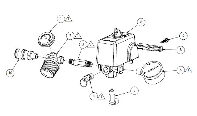
| PARTS LIST / LISTE DE PIÈCES / LISTA DE LA PIEZAS | |||||
| Item Article Artículo | Part No No / P Núm / P | Qty Qté Cant |
Description |
Descripción |
Descripción |
| 1 | 032-0056 | 1 | Gauge, 255# 1/8” back connect | Manomètre | Manómetro |
| 2 | 019-0182 | 1 | Regulator | Régulateur | Regulador |
| 3 | 065-0004 | 1 | Nipple, 1/4” x 2” | Manchon fileté | Niple |
| 4 | 136-0005 | 1 | Valve, ASME | Soupape | Válvula |
| 5 | 032-0025 | 1 | Gauge, 300# 1/4” bottom connect | Manomètre | Manómetro |
| 6 | 034-0226 | 1 | Switch, pressure (includes items 7-9) | Interrupteur (inclut les articles 7-9) | Manómetro (incluye los artículos 7-9) |
| 7 | 136-0090 | 1 | Valve, bleeder | Soupape | Válvula |
| 8 | 071-0033 | 1 | Strain relief | Soulagement de traction | Aliviador de esfuerzo |
| 9 | 061-0216 | 1 | Screw | Vis | Tornillo |
| 10 | 036-0031 | 1 | Quick connect coupler | Raccord rapide | Acoplador especial |


