![]() LiFePO4 48V Battery Pack
LiFePO4 48V Battery Pack
User Manual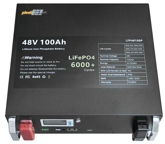 48V LiFePO4
BATTERY PACK
https://www.plentisolar.de/
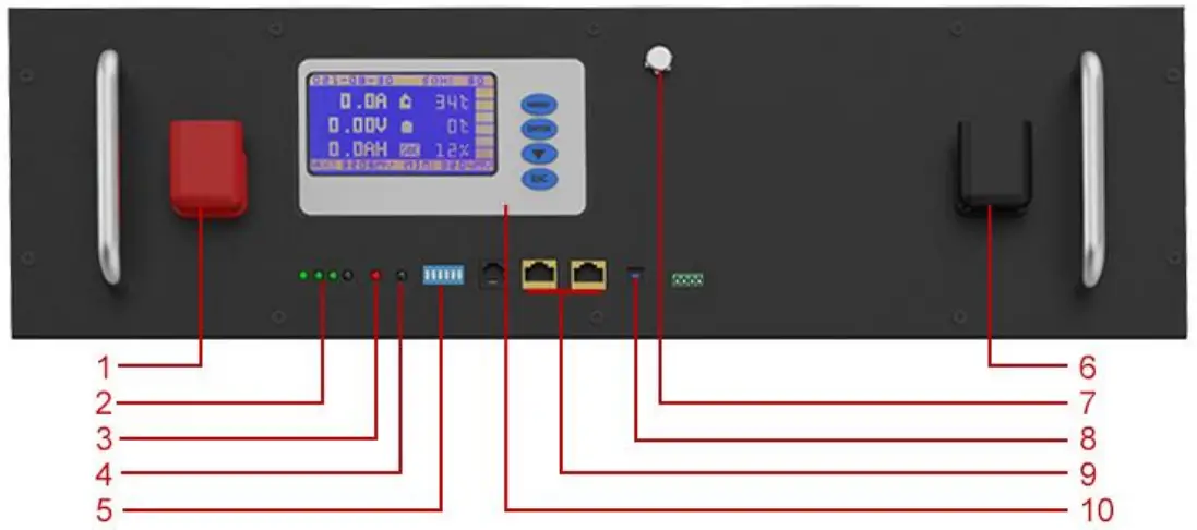
Layout of Front Panel
| NO. | Name | Function |
| 1 | Positive Terminal | Charge & Discharge |
| 2 | SOC | Indicators For Capacity |
| 3 | ALM | Indicator For Alarms |
| 4 | RUN | Indicator For Running Status |
| 5 | ADD | Dial Code Of Communication |
| 6 | Negative Terminal | Charge & Discharge |
| 7 | Power Switch | ON/OFF Switch |
| 8 | Reset | Activate/Hibernate BMS |
| 9 | RS485*2/CAN*2 | Communication Interface |
| 10 | LCD Screen | Display Battery Information |
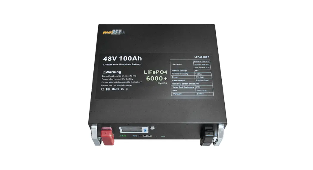
Battery Specifications
| Nominal Parameters | ||||
| Model No | LFP48100P | LFP48120P | LFP48150P | LFP48200P |
| Voltage | 51.2 V | 51.2 V | 51.2 V | 51.2 V |
| Capacity | 100Ah | 120Ah | 150Ah | 200Ah |
| Energy | 5KWh | 6KWh | 7KWh | 10KWh |
| Dimensions (L * W * H mm) | 480*440*160 | 480*440*200 | 480*440*200 | 480*440*255 |
| Weight (KG) | Approx 48 | Approx 55 | Approx 60 | Approx 85 |
| Built-in BMS | 16S 100A | 16S 100A | 16S 200A | 16S 200A |
| Electrical Parameters | ||||
| Operation Voltage | 51.2 VDC | 51.2 VDC | 51.2 VDC | 51.2 VDC |
| Max. Charging Voltage | 58.4 VDC | 58.4 VDC | 58.4 VDC | 58.4 VDC |
| Cut-off Discharge Voltage | 43.2 VDC | 43.2 VDC | 43.2 VDC | 43.2 VDC |
| Max. Continuous Charging and Discharging Current | 100A | 100A | 150A | 200A |
| Peak Discharge Current | 150A (5s) | 150A (5s) | 250A (5s) | 250A (5s) |
| Basic Parameters | ||||
| Life Time(25°C) | 10 years | |||
| Communication Method | RS485/CAN | |||
| Display Method and Language | LCD, English | |||
| Life Cycles (80% DOD, 25°C) | ≥6000 times Cycles | |||
| Operating Temperature Range | -20℃~70℃ | |||
| Operating Humidity Range | 10%~85% | |||
Working Mode
3.1. Basic Mode
3.1.1. Charging Mode
The BMS turns on the charging MOSFET for charging when it detects an external charging voltage of ≥48V, and the cell voltage and temperature are within the chargeable range. When the charging current reaches the effective charging current, it enters the charging mode. Both charging and discharging MOSFETs are on in charge mode.
3.1.2. Discharging Mode
The BMS enters the discharge mode when it detects that the load is connected and the cell voltage and temperature are within the dischargeable range and the discharge current reaches the effective discharge current.
3.1.3. Standby Mode
When neither of the above two modes is met, it enters standby mode.
3.1.4. Hibernation Mode
The BMS will enter sleep (shutdown) mode after a specific time of standby, or when the battery triggers undervoltage protection, or when the key is executed to shutdown or when the upper computer executes the shutdown command mode.
The wake-up conditions of hibernation mode:
- Make charging to activation;
- Press the button to power on.
3.2. Description of Buzzer
Buzzer function can be enabled or disabled via the upper computer, factory default is disabled.
3.3. Description of Reset Button
When the BMS is dormant, press the button for 1S and then release it, the protection board will be activated and the LED will light up from “L4” for 0.5 seconds.
When the BMS is active, press the button for 3S and then release it, the board will be dormant and the LED will light up from “RUN” for 0.5 seconds.
3.4. Dormancy and Activation
3.4.1. Dormancy
The system will enter low-power mode when any of the following conditions are met.
- Single cell undervoltage protection or overall undervoltage protection is not released within 30 minutes.
- Press the button for 3 seconds and then release the button.
- The minimum individual voltage is lower than the sleep setting voltage (default value 3150mV) and the duration reaches the sleep delay time (default value 1440 minutes), and there is no communication and no charging/discharging in meanwhile.
- Forced shutdown via the upper computer software.
Note: Before entering hibernation, make sure that no external voltage is connected to the P-terminus, otherwise it will not be able to enter the low-power mode.
3.4.2. Activation
When the system is in low-power mode and any of the following conditions are met, the system will exit low-power mode and enter normal operation mode.
- Connect to the charger, the charger output voltage should be greater than or equal to 48V.
- Press the button for 1S, after releasing the button.
LED Indicator Description
4.1. LED Indicator Description
Four green capacity indicators, one red alarm indicator, one green operation indicator
| SOC | ALM | RUN | |||
4. 2 SOC Capacity Indicator
| Status | Charge | Discharge | ||||||
| Capacity Indicator | L1● | L2● | L3● | L4● | L1● | L2● | L3● | L4● |
| 0~25% | OFF | OFF | OFF | Flash 2 | OFF | OFF | OFF | ON |
| 25~50% | OFF | OFF | Flash 2 | ON | OFF | OFF | ON | ON |
| 50~75% | OFF | Flash 2 | ON | ON | OFF | ON | ON | ON |
| 75~100% | Flash 2 | ON | ON | ON | ON | ON | ON | ON |
| Running Indicator● | ON | Flash 3 | ||||||
4.3 Status Indicator
| Status | Warning/Normal | RUN | ALM | SOC LED | Mark | |||
| ● | ● | ● | ● | ● | ● | |||
| OFF | OFF | OFF | ALL OFF | |||||
| Standby | Normal | Flash 1 | OFF | ON as battery capacity indicates | ||||
| Warning | Flash 1 | Flash 2 | ||||||
| Charge | Normal | ON | OFF | |||||
| Over Voltage Warning | ON | OFF | ||||||
| Over Current, Over Voltage and Temperature Warning | ON | Flash 2 | ||||||
| Over Voltage Protection | Flash 1 | OFF | ||||||
| Over Current Protection | ON | OFF | ||||||
| Discharge | Normal | Flash 3 | OFF | |||||
| Warning | Flash 3 | Flash 2 | ||||||
| Low Voltage Protection | Flash 1 | Flash 2 | ||||||
| Protection of Overcurrent, Short Circuit, Temperature, Reverse Polarity etc | OFF | ON | ALL OFF | |||||
4.4. Flash Instruction of LED Indicators
| ON | OFF | |
| Flash 1 | 0.25 S | 3.75 S |
| Flash 2 | 0.5 S | 0.5 S |
| Flash 3 | 0.5 S | 1.5 S |
Communication
With RS485 and CAN interface, which supports communicating with multiple machines in parallel and with the upper computer. RS485 baud rate is 19200, CAN baud rate is 500K.
RS485 INTERFACE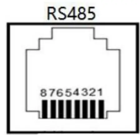
| 8P8C RJ45 Pins Assignment (RS485) | |
| Pins | Definition |
| 1、3 | RS485_B |
| 7 | RS485_A |
| 2、6 | GND |
| 4 | CANH |
| 5 | CANL |
| 8 | NC |
The multi-unit parallel bus connections are shown in the following figure. 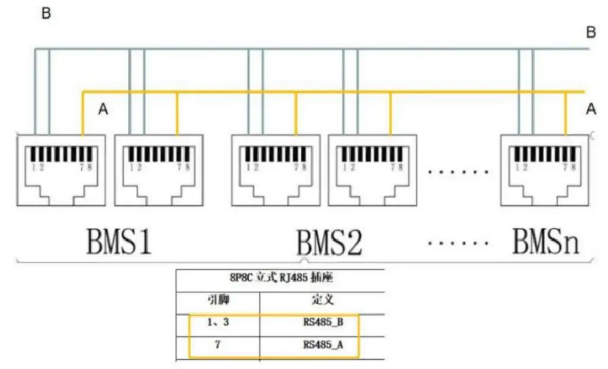
| Instructions For Compatibility With Inverters | |
| 1. Compatible inverter brands list | Victron, Pylontech, Goodwe, Growatt, Voltronic, Deye, LXP, Sofar, GinLong, SMA, Sacolor, |
| 2. If your inverter not on our list above | ① If you can provide the communication protocol (a kind of code) of your inverter, we can customize the BMS to be compatible with your inverter, minimum order quantity for customzed is 50 pcs. |
| ② Without communication protocol, inverter cannot communicate with our battery. You need to make some setting on your inverter, for example, select the user-defined mode and set the corresponding voltage level(according to the inverter user manual), so that they can work together without communication. | |
| More questions about inverter communication, pls contact our customer service. | |
Assignment of ID Addresses
When performing parallel communication operation of multiple machines, you need to configure the dialing address of each PACK first. When the BMS is configured for stand-alone operation, and the dialing address can be any address; when the BMS is configured for cascade operation mode, the slave dialing address is selected from 1 to 31, and the host dialing address is selected from 32 or 48 according to the inverter brand.
You can enter the address code of the master or slave battery in the system parameters of the upper computer to detect and communicate.
| Code | ADD | PACK NO. | Remarks | |||||
| 1 | 2 | 3 | 4 | 5 | 6 | |||
| ON | OFF | OFF | OFF | OFF | OFF | 1 | PACK 1 | Slave Pack |
| OFF | ON | OFF | OFF | OFF | OFF | 2 | PACK 2 | |
| ON | ON | OFF | OFF | OFF | OFF | 3 | PACK 3 | |
| OFF | OFF | ON | OFF | OFF | OFF | 4 | PACK 4 | |
| ON | OFF | ON | OFF | OFF | OFF | 5 | PACK 5 | |
| OFF | ON | ON | OFF | OFF | OFF | 6 | PACK 6 | |
| ON | ON | ON | OFF | OFF | OFF | 7 | PACK 7 | |
| OFF | OFF | OFF | ON | OFF | OFF | 8 | PACK 8 | |
| ON | OFF | OFF | ON | OFF | OFF | 9 | PACK 9 | |
| OFF | ON | OFF | ON | OFF | OFF | 10 | PACK 10 | |
| ON | ON | OFF | ON | OFF | OFF | 11 | PACK 11 | |
| OFF | OFF | ON | ON | OFF | OFF | 12 | PACK 12 | |
| ON | OFF | ON | ON | OFF | OFF | 13 | PACK 13 | |
| OFF | ON | ON | ON | OFF | OFF | 14 | PACK 14 | |
| ON | ON | ON | ON | OFF | OFF | 15 | PACK 15 | |
| OFF | OFF | OFF | OFF | ON | OFF | 16 | PACK 16 | |
| ON | OFF | OFF | OFF | ON | OFF | 17 | PACK 17 | |
| OFF | ON | OFF | OFF | ON | OFF | 18 | PACK 18 | |
| ON | ON | OFF | OFF | ON | OFF | 19 | PACK 19 | |
| OFF | OFF | ON | OFF | ON | OFF | 20 | PACK 20 | |
| ON | OFF | ON | OFF | ON | OFF | 21 | PACK 21 | |
| OFF | ON | ON | OFF | ON | OFF | 22 | PACK 22 | |
| ON | ON | ON | OFF | ON | OFF | 23 | PACK 23 | |
| OFF | OFF | OFF | ON | ON | OFF | 24 | PACK 24 | |
| ON | OFF | OFF | ON | ON | OFF | 25 | PACK 25 | |
| OFF | ON | OFF | ON | ON | OFF | 26 | PACK 26 | |
| ON | ON | OFF | ON | ON | OFF | 27 | PACK 27 | |
| OFF | OFF | ON | ON | ON | OFF | 28 | PACK 28 | |
| ON | OFF | ON | ON | ON | OFF | 29 | PACK 29 | |
| OFF | ON | ON | ON | ON | OFF | 30 | PACK 30 | |
| ON | ON | ON | ON | ON | OFF | 31 | PACK 31 | |
| OFF | OFF | OFF | OFF | OFF | ON | 32 |
PACK 32 | Master Pack: if your inverter is from other brands except Victron, SMA and Growatt, the ADD of master pack is 32 |
| OFF | OFF | OFF | OFF | ON | ON | 48 | Master Pack: if your inverter is from Victron, SMA or Growatt, the ADD of master pack is 48 | |
LCD Display Introduction
 Button description:
MENU:Enter the management system.
ENTER:Enter to the sub-menu.
▼:Move the cursor down or to next page.
ESC:Return to the previous menu.
7.1. Power-on screen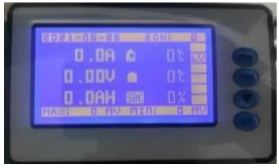
| System Date | SOH |
| Charging/Discharging Current | Environmental Temperature |
| Total Voltage | Max. Temperature of Battery Cell |
| Remaining Capacity | SOC |
| Max. Voltage of Single Unit | Min. Voltage of Single Unit |
Battery protection status:
Over Voltage: OV
Low Voltage: LV
Over Temp: OT
Low Temp: LT
Over Current: OC
Short Circuit: SC
Note: When there is protection situation of the battery, there will show the corresponding protection status, otherwise, the protection status will not be showed.
7.2. Press “MENU” to enter the main menu
(Note: “》” means there is a sub-menu, press “ENTER” to enter the sub-menu)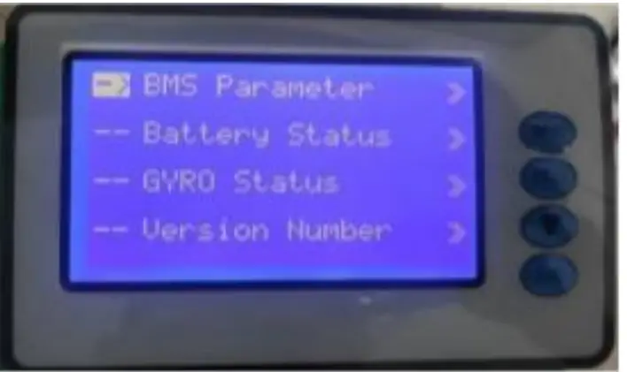
| BMS Parameter | 》 |
| Battery Status | 》 |
| GYRO Status | 》 |
| Version Number | 》 |
7.2.1. Move the cursor to “BMS Parameter” and press “Enter” to enter.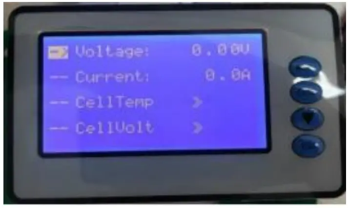
| Voltage | 0.00V |
| Current | 0.0A |
| Cell Temp | 》 |
| Cell Volt | 》 |
Move the cursor to “Cell Temp” and press “Enter” to check the battery temperature information, then press ” ▼” to turn the page.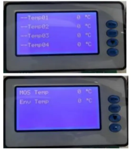
| Temp 01 | xx℃ |
| Temp 02 | xx℃ |
| Temp 03 | xx℃ |
| Temp 04 | xx℃ |
| MOS Temp | xx℃ |
| Env Temp | xx℃ |
Move the cursor to “Cell Volt” and press “Enter” to check the battery voltage information, then press “▼” to turn the page.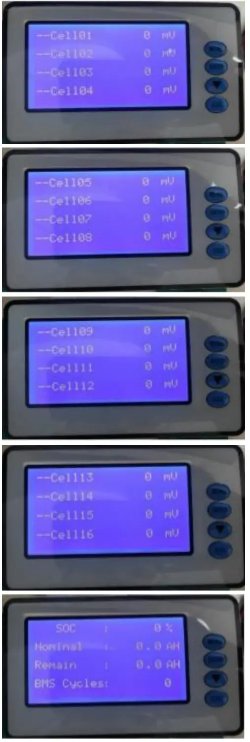
| Cell 01 | xxxxmV |
| Cell 02 | xxxxmV |
| Cell 03 | xxxxmV |
| Cell 04 | xxxxmV |
| Cell 05 | xxxxmV |
| Cell 06 | xxxxmV |
| Cell 07 | xxxxmV |
| Cell 08 | xxxxmV |
| Cell 09 | xxxxmV |
| Cell 10 | xxxxmV |
| Cell 11 | xxxxmV |
| Cell 12 | xxxxmV |
| Cell 13 | xxxxmV |
| Cell 14 | xxxxmV |
| Cell 15 | xxxxmV |
| Cell 16 | xxxxmV |
| SOC | xx% |
| Nominal Capacity | 0.0AH |
| Remain Capacity | 0.0AH |
| BMS Cycles | 0 |
7.2.2. Move the cursor to “Battery Status” and press “Enter” to check the battery status information, then press “▼” to turn the page.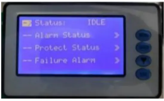
| Status | IDLE/DISCHG/CHARGE/FULL |
| Alarm Status | 》 |
| Protect Status | 》 |
| Failure Alarm | 》 |
Move the cursor to “Alarm Status” and press “Enter” to check the battery alarm information, then press “▼” to turn the page.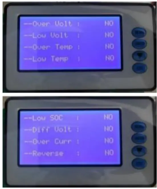
| Over Volt | YES/NO |
| Low Volt | YES/NO |
| Over Temp | YES/NO |
| Low Temp | YES/NO |
| Low SOC | YES/NO |
| Diff Volt | YES/NO |
| Over Curr | YES/NO |
| Reverse | YES/NO |
Move the cursor to “Protect Status” and press “Enter” to check the battery protection information, then press “▼” to turn the page.
| Over Volt | YES/NO |
| Low Volt | YES/NO |
| Over Temp | YES/NO |
| Low Temp | YES/NO |
| Over Curr | YES/NO |
| Short Curr | YES/NO |
Move the cursor to “Failure Alarm” and press “Enter” to check the battery fault information, then press “▼” to turn the page. 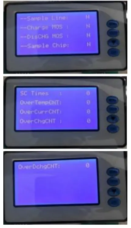
| Sample Line | N/Y |
| Charge MOS | N/Y |
| Dis CHG MOS | N/Y |
| Sample Chip | N/Y |
| SC Times | 0 |
| Over Temp CNT | 0 |
| Over Cur CNT | 0 |
| OVER Chg CNT | 0 |
| Over Dchg CNT | 0 |
7.2.3. Move the cursor to “GYRO Status” and press Enter to check the gyroscope information, then press “▼” to turn the page. (Note: This gyroscope is optional)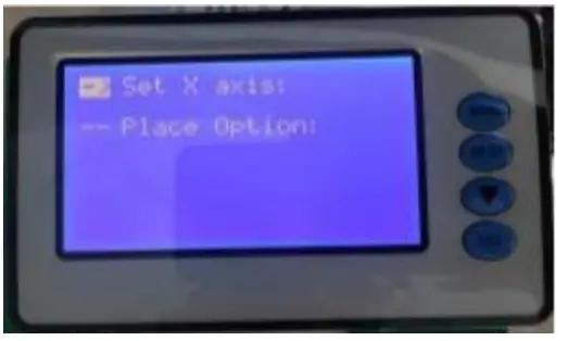
| Set X axis: | |
| Place Option: |
7.2.4. Move the cursor to “Version number” and press Enter to check the version information, then press “▼” to turn the page.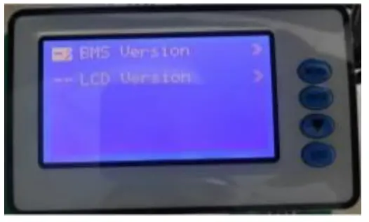
| BMS Version | 》 |
| LCD Version | 》 |
Move the cursor to “BMS Version” and press “Enter” to check the BMS version information.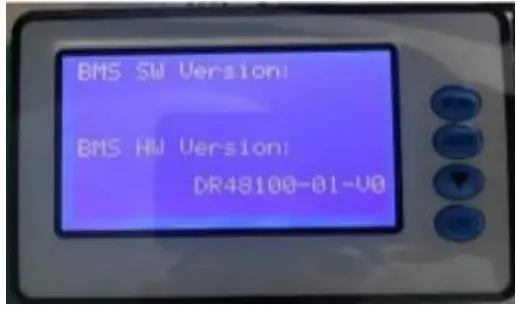
| BMS SW Version | |
| BMS HW Version |
Move the cursor to “LCD Version” and press “Enter” to check the LCD version information.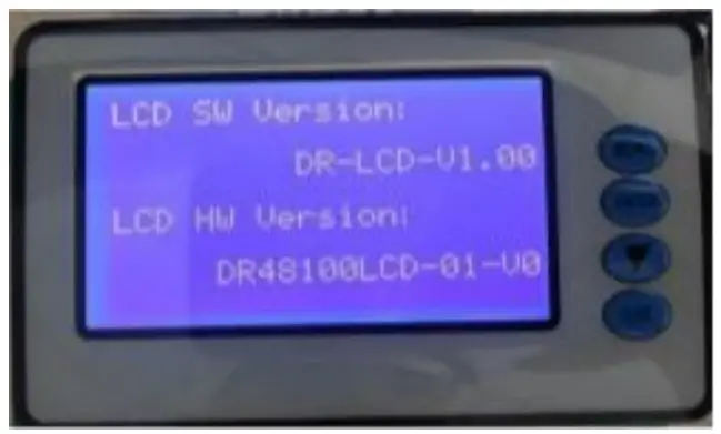
| LCD SW Version | |
| LCD HW Version |
7.3. Dormancy and Activation Function
After 1 minute of no button operation in normal running, the display screen will be off (only the backlight is off). Pressing any button while the screen is off will allow the screen light and operate normally.
Upper Computer Software Introduction
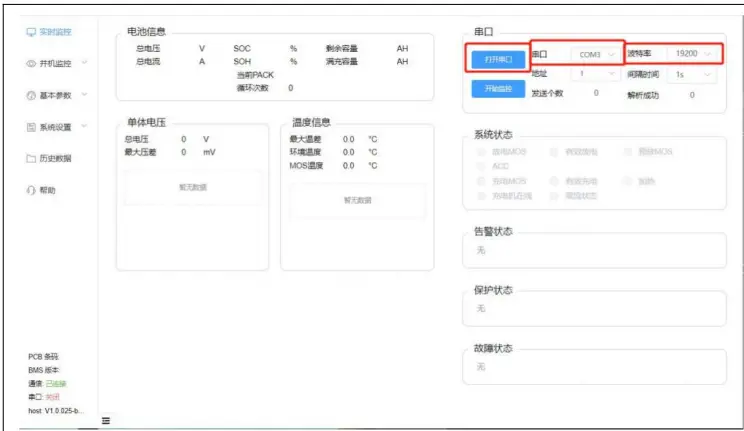 Enable the monitoring software, select the communication interface of the corresponding device, select the corresponding baud rate, and finally click “Open Serial Interface” to communicate with BMS and get the basic parameters.
 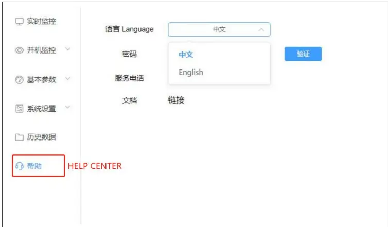 You can switch the version in Chinese or English in help center
 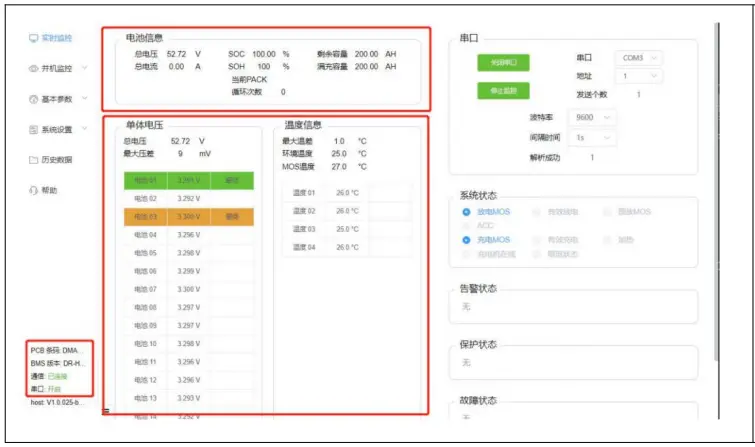 After the BMS communicates with the upper computer, you can monitor the basic parameters and status of the battery in real time. These information include battery voltage, current, SOC, SOH, cycle count, battery temperature, alarm status, protection status, etc.
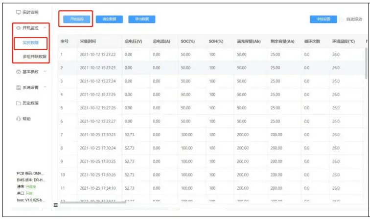 You can view the real-time data storage of the BMS and export as excel tables.
 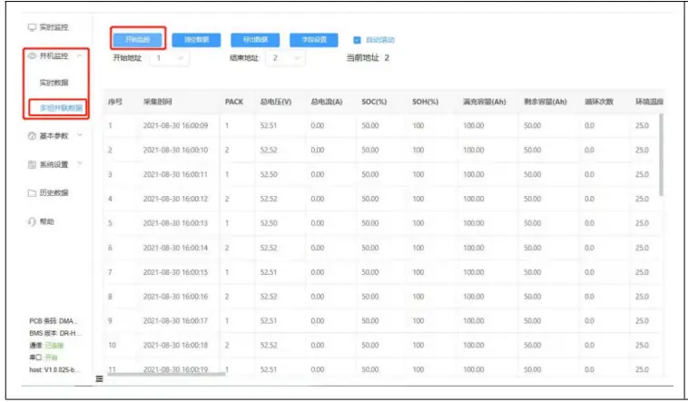 When monitoring multiple packs, you need to set the start and end address of packs manually, you can check and comparethe data of each pack. And you can also export as excel table.
 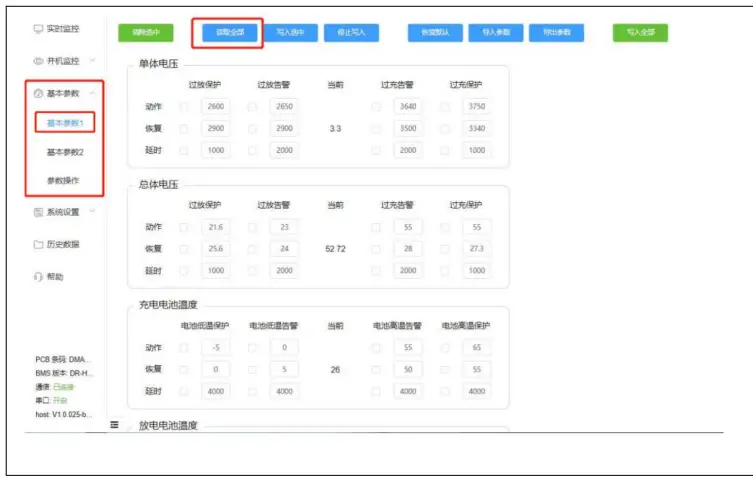 Basic parameters 1.Click “Read All” when enter for the first time. This section includes reading basic parameter information, restoring default parameters, writing individual parameters, writing all parameters, importing parameters and exporting parameters (it is not recommended to manually modified default parameters).
 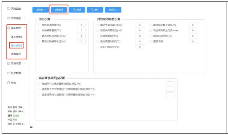 Basic parameters 2. Click “Read All” when enter for the first time. This section includes heating settings, other BMS parameter information, etc. (it is not recommended to manually modified default parameters).
 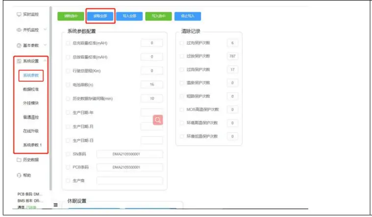 System parameter setting.
Click “Read All” when enter for the first time. You can monitor the BMS parameters configuration, sleep settings and BMS information in real-time(it is not recommended to
manually modified default parameters). 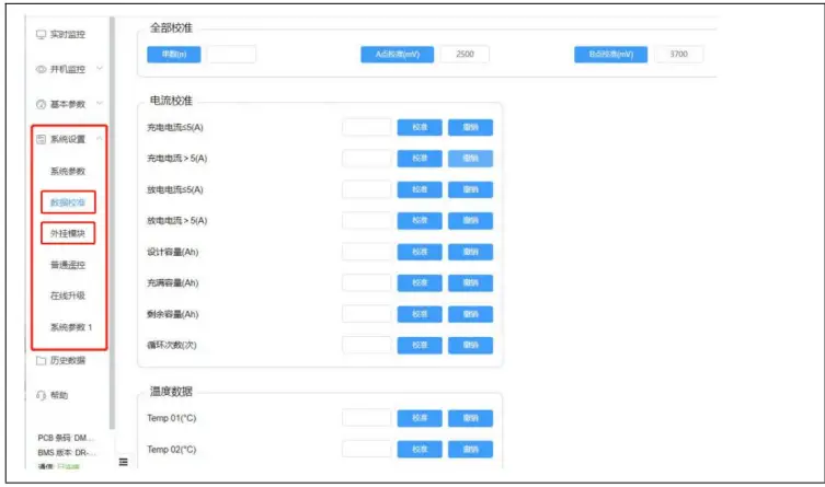 Data calibration: Here is calibration content of BMS data (all has calibrated by factory, not recommended for private calibration).
Plug-in modules: Here will contains information about some additional functional modules. 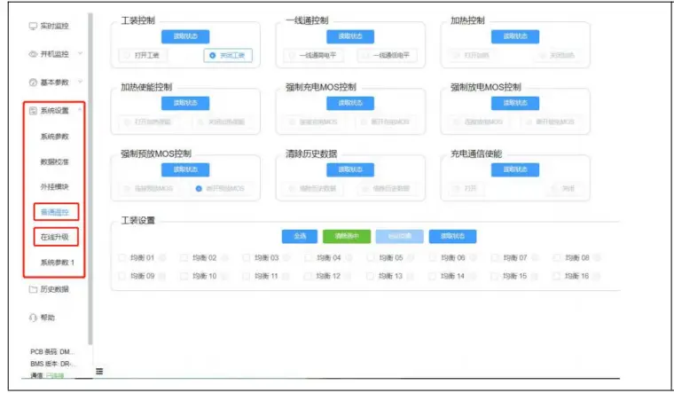 Normal remote control:
Here includes the control of charging and discharging MOS, heating and other states (please consult the manufacturer for operation).
Online upgrade: software online upgrade function of BMS (please consult the manufacturer for operation).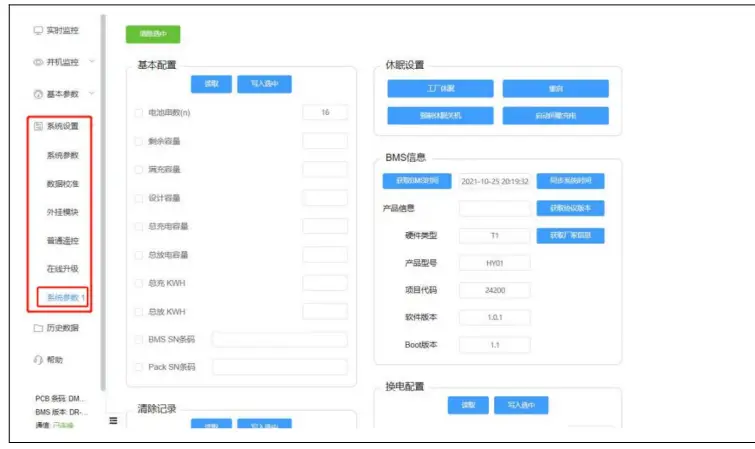 System Parameters 1.
Here includes some basic parameter information and dormancy settings. 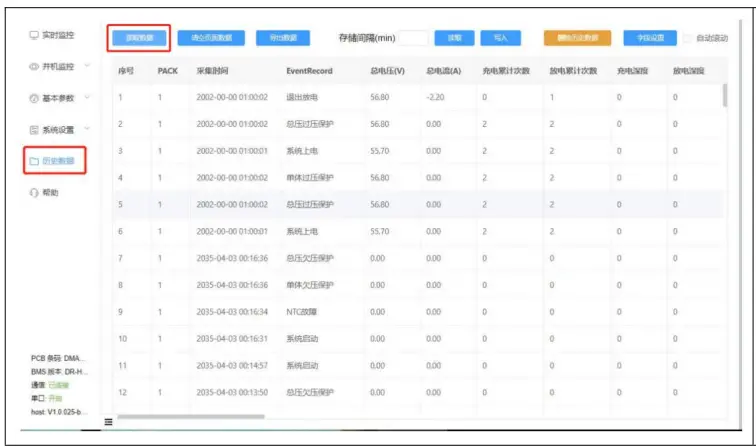 Click “Read Data” to get real-time history data and export data, and view basic data information of battery packs.
List of Accessories
NO. | ITEM | PICTURE | QTY | Remarks |
| 1 | Battery Pack | 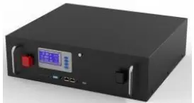 | 1 | |
| 2 | Parallel Power Cable |  | 2 | For 48V 100AH/120AH: 6 gauge cable 0.3M + SC25-8 connector For 48V 150AH/200AH: 4 gauge cable 0.4M + SC35-8 connector |
| 3 | Parallel Communication Cable | 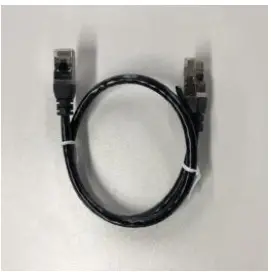 | 1 | RJ45 cable 0.5M |
| 4 | Upper computer Connecting Cable | 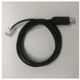 | 1 | RJ45 to USB cable 2M |
| 5 | Screws |  | 4 | M8 |
![]()


