
![]()
Energy Storage LiFePO4 Battery
User manual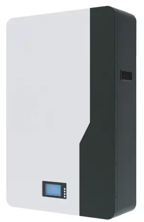
POW0LIO48200 Energy Storage LiFePO4 Battery
lmportant safety instructions
lmportant safety instructions
Please keep this manual for future reference.
This manual contains all the safety installation and operation instructions of the M15S series energy storage LiFePO4 battery.
Please read all instructions and precautions in the manual carefully before installation and use.
- To avoid personal injury, users should not disassemble it by themselves, since the energy storage LiFePO4 battery has unsafe voltage inside. If need repairs, please contact our company’s professional maintenance personnel.
- Do not install the energy storage LiFePO4 battery in a place where children can touch.
- Do not install the energy storage LiFePO4 battery in harsh environments such as damp greasy, flammable, explosive, or dust accumulation.
- When the energy storage LiFePO4 battery is working, please do not open the box.
- lt is recommended to install a suitable fuse or circuit breaker externally.
- After installation, check whether all line connections are tight to avoid the risk of heat accumulation due to virtual connection.
- Wall mounted energy storage battery shall be charged with 48V DC power supply, parallel connection with other AC power supply or different voltage and brand batteries is prohibited.
Basic information
1.1 Product overview
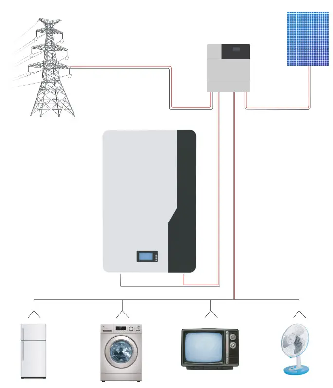
M15S series energy storage battery is mainly used in the field of household power storage.At the same time, it is also suitable for the internal energy storage of RV, household energy storage and temporary buildings. lt adopts high-performance and long-life lithium iron phosphate battery as the basic energy storage unit, combined with advanced lithium-ion battery management system industrial design of household products and other technologies. Ensure that products have high reliability and high industrialization standards.
M15S series energy storage battery covers the energy demand of a single machine from the 5.0kwh to 10.0kwh, and the rated output voltage is 48V.
M15S series products have wall mounting function and can support external parallel use function, which greatly improves the convenience of use.
Through scientific and reasonable active heat dissipation. M15S series energy storage battery improves the consistency of internal temperature field, prolongs service life, and
enables the product to continuously output high current.
1.2 Features
- The external LCD screen is used to monitor the energy storage battery data and operating status in real time.
- The battery adopts high-performance lithium iron phosphate battery with high safety performance and long service life.
- M15S series energy storage battery adopts intellizent air cooling and heat dissipation to improve the reliability of the product.
- External weak current switch reduces product power consumption and improves the safety of transportation and storage.
- With RS485/CAN communication function, it can easily communicate with the equipment with communication.
- External wireless module can be connected for remote data monitoring and corresponding control.
- The energr storage battery is euipped with foot pad and wall mounting bracket, which can met the installation and use in different places.
- lt has multiple protection functions to protect the safety of power supply inan all-round way.
- The output is stable and can be connected to different loads with in the voltage rang.
- Support up to 15 independent modules for parallel use.
1.3 Function description
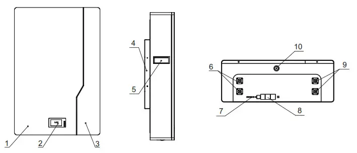
| 1 | White plate | 6 | M6 Positive terminal (2pcs) |
| 2 | LCD display | 7 | Battery indicator |
| 3 | Black plate | 8 | RS485/CAN |
| 4 | Wall mounted bracket | 9 | M6 Negative terminal (2pcs) |
| 5 | Handle | 10 | OFF/ON |
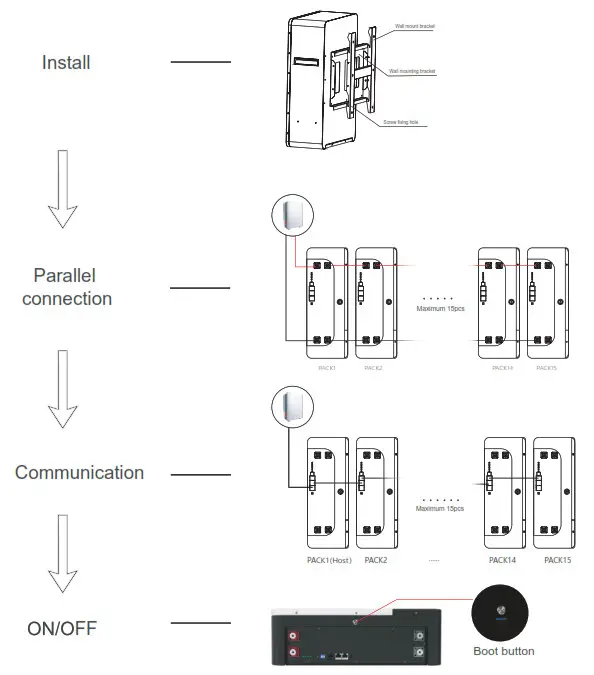
Installation process
Installation instructions
3.1 Installation notes
Before installation, please read this manual carefully and familiarize the installation steps.
- Be sure to leave a certain space around for heat dissipation during installation.
- Avoid sunlight direct and rainwater infiltration during outdoor installation to cause battery damage.
- Do not place metal products near the place of the energy storage LiFePO4 battery installation to prevent short circuits.
- Virtual connection points and corroded wires may generate high heat, and the molten insulation layer will burn surrounding materials and even cause a fire. Therefore, it must be ensured that the connector has been tightened and the wires should be secured with cable ties to avoid loosening of the connector due to shaking during
mobile applications. - After the battery switch is turned off,there is still high voltage inside the energy storage case. Please do not open or touch the internal components, and external short circuit is strictly prohibited.
- Please do not install it in a harsh environment where a large amount of damp, greasy, flammable and explosive dust gathers.
- lt is forbidden to reverse the charging and discharging terminals of the battery, other wise it is very easy to damage the battery or cause unpredictable risks.
- When the fan is working, please do not touch it to avoid injury.
- When installing the battery on the wall, you must first ensure the bearing capacity of the wall and check whether the screws are installed firmly to avoid unnecessary danger.
- lf an injury occurs during installation or use, please seek medical attention in time.
3.2 Installation and connection
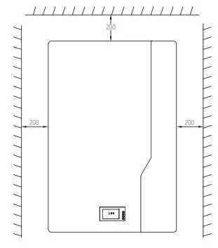
Installation and connection must comply with national and local electrical code requirements. According to the current situation, firstly, choose the corresponding wire or a wire with a larger wire diameter to avoid unnecessary troubles during use. Secondly, determine the installation location. Thirdly, when installing, please make sure to leave at least 200 mm of space at the air outlets on both sides of the energy storage battery to ensure natural convection heat dissipation.
3.3 Recommended external wiring diameter and switch selection.
| Model | Recommended extemal wiring diameter | Battery continuous current circuit breaker |
| POW-LIO48100-15S | 25mm² /4AWG | 100A |
| POW-LIO48200-15S | 25mm² /4AWG | 100A |
Note: The wiring diameter is for reference only. If the distance between the load and the battery is relatively long,use a larger wire to reduce the voltage and improve the system performance. The above wiring diameter and circuit breaker are only recommendations, please follow the actual choose the appropriate wire diameter and circuit breaker according to the situation.
3.4 Schematic diagram of the wall mounted installation
![]() Warning: Danger of explosion! In order to avoid accidents, do not reverse connect the charging and discharging ports or short circuit, and do not install them in a closed environment. Rain proof and moisture-proof protection must be installed in the outdoor.
Warning: Danger of explosion! In order to avoid accidents, do not reverse connect the charging and discharging ports or short circuit, and do not install them in a closed environment. Rain proof and moisture-proof protection must be installed in the outdoor.
Attention!! The above steps can be omitted without wall mounting.
Attention!! When Only one battery is using inverter below 5kw or other loads below 5kw are recommended.
Attention!! Before making the final DC connection, please ensure that the battery switch / DC circuit breaker is disconnected, and ensure that the positive (+) must be connected to the negative positive(+), and the negative (-) must be connected to the negative(-).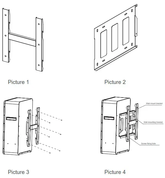
As shown in the pictures above:
- According to the actual situation,first install the wall mounting plate with M8 expansion screw on the wall to ensure that the installation is firm (picture 1).
Note: the height of the expansion screw protruding from the wall shall be controlled within 25mm to avoid interference with the battery box during installation (Picture 2). - Fix the wall mounting bracket on the outer box of the battery with M6 screws, and ensure that the bolts are tightened with a torque of 2-3 nm (Picture 3).
- After all the above are installed, hang they on the wall mounting bracket, and final lock the case and wall mounting bracket with M5 screws to prevent accidental tripping(Picture 4).
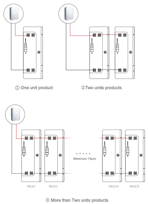
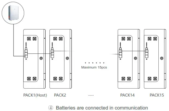
Schematic diagram of connecting
Note:
- When the battery pack is used in parallel, it is necessary to distinguish different packs by hardware address, and the hardware address of each pack in the whole battery pack is unique.
- lt must set up a park for the host park.The inverter communicate with host pack via PRS485/CAN. The hardwareaddress can be set successively through the dial switch on theboard.
Recommended setting data of inverter:
| Battery model | LiFePO4/Lithium battery | |
| Model | POW-LIO48100-15S | POW-LIO48200-15S |
| Discharge cut-off voltage | 42 | 42 |
| Over discharge recovery | 44 | 44 |
| Normal charging voltage | 58.4 | 58.4 |
| Surge charging voltage | 58 | 58 |
| Overvoltage protection | 54.8 | 54.8 |
| Overvoltage recovery | 52 | 52 |
LED instructions
Table1 LED working status indication
| state | normal/warning/protect | RUN | ALM | Battery indicator LED | illustrate | |||
| • | • | • | • | • | • | |||
| shutdown | hibernate | extinguish | extinguish | extinguish | extinguish | extinguish | extinguish | annihilate |
| Standby | normal | flash 1 | extinguish | According to the battery indicator | standby mode | |||
| alert | flash 1 | flash 3 | Module low voltage | |||||
| Charge | normal | Always bright | extinguish | According to the battery indicator (battery indication maximum LED flashes 2) | Maximum battery LED flashes Move (flashing 2), overcharge warning ALM does not flash during alarm | |||
| alert | Always bright | flash 3 | ||||||
| Overcharge prn | Always | extinguish | Always bright | Always bright | Always bright | Always bright | If there is no utility power, indicate Light goes to standby | |
| temperature, overcurrent, Failsafe | extinguish | Always bright | extinguish | extinguish | extinguish | extinguish | stop charging | |
| discharge | normal | flash 3 | extinguish | According to the battery indicator | stop charging | |||
| alert | flash 3 | flash 3 | ||||||
| Undervoltage protection | extinguish | extinguish | extinguish | extinguish | extinguish | extinguish | stop charging | |
| temperature, overcurrent, short circuit, Reverse connection, failsafe | extinguish | Always bright | extinguish | extinguish | extinguish | extinguish | stop charging | |
| invalid | extinguish | Always bright | extinguish | extinguish | extinguish | extinguish | Stop charging and discharging | |
Table2 Description of capacity indication
| state | Charge | discharge | |||||||
| capacity indicator | L4 • | L3 • | L2 • | L1 • | L4 • | L3 • | L2 • | L1 • | |
| Battery (%) | 0-25% | extinguish | extinguish | extinguish | extinguish | extinguish | extinguish | extinguish | constant |
| 25-50% | extinguish | flash 2 | flash 2 | constant | extinguish | extinguish | constant | constant | |
| 50-75% | flash 2 | flash 2 | constant | constant | extinguish | constant | constant | constant | |
| 75-100% | flash ‘ | constant | constant | constant | constant | constant | constant | constant | |
| Running lights • | constant | Blink (blink 3) | |||||||
Table 3 LED flashing description
| flashing method | Bright | extinguish |
| flash 1 | 0.25S | 3.75S |
| flash 2 | 0.5S | 0.5S |
| flash 3 | 0.5S | 1.5S |
Remarks: The LED indicator alarm can be enabled or disabled through the host computer, and the factory default is enabled.
Key Description
- When the BMS is in sleep state, press the button (3~6S) and release it, the protection board will be activated, and the LED indicators will light up sequentially from “RUN” for 0.5 seconds.
- When the BMS is active, press the button (3~6S) and release it, the protection board will be put to sleep, and the LED indicators will light up sequentially for 0.5 seconds from the lowest battery indicator.
- When the BMS is active, press the button (6~10S) and release it, the protection board will be reset, and all the LED lights will light up at the same time for 1.5 seconds.
- After the BMS is reset, the parameters and functions set by the host computer are still retained. If it is necessary to restore the initial parameters, it can be achieved through the ” restore default value” of the host computer, but the relevant operation records and stored data remain unchanged (such as power, cycle times, etc.).
BMS communication settings
6.1 BMS communication and setting
When the load (such as inverter) needs to communicate with the battery, in order to establish normal communication with the load, BMS needs to set the following settings for each brand. The RS485 communication protocols of inverters are different,but there are several RS485 communication protocols inside the inverter to match the battery. When using,you can directly select the communication protocol code in the inverter for matching. If you have other problems, please consult the supplier.
Battery BMS interface pin foot definition as shown in the following figure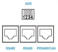
“ADS” is used for parallel use of battery packs.
PACK can be distinguished by hardware address.
The definition of ADS master-slavead dress refers to communication address selection specification. “PRS485/CAN” battery pack can communicate with the upper computer or inverter and the reverse control integrated machine through the interface. “RS485” is used in parallel for battery pack,and the main communicates with pack from the interface.

| The battery communication interface adopts 8P8C RJ45 socket. | |||
| RS485 | PRS485/CAN | ||
| PIN | Definition | PIN | Definition |
| 1. 8 | RS485-B | 1 8 | RS485-6 |
| 2. 7 | RS485-A | 2 7 | RS485-A |
| 4 | CAN-H | ||
| 5 | CAN-L | ||
6.2 Communication address selection specification
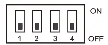
| Address | Code switch position | Illustrate | |||
| 1# | 2# | 3# | 4# | ||
| 0 | OFF | OFF | OFF | OFF | Stand-alone use, no cascade |
| 1 | ON | OFF | OFF | OFF | Set to Pack 1 (Host) |
| 2 | OFF | ON | OFF | OFF | Set to Pack 2 |
| 3 | ON | ON | OFF | OFF | Set to Pack 3 |
| 4 | OFF | OFF | ON | OFF | Set to Pack 4 |
| 5 | ON | OFF | ON | OFF | Set to Pack 5 |
| 6 | OFF | ON | ON | OFF | Set to Pack 6 |
| 7 | ON | ON | ON | OFF | Set to Pack 7 |
| 8 | OFF | OFF | OFF | ON | Set to Pack 8 |
| 9 | ON | OFF | OFF | ON | Set to Pack 9 |
| 10 | OFF | ON | OFF | ON | Set to Pack 10 |
| 11 | ON | ON | OFF | ON | Set to Pack 11 |
| 12 | OFF | OFF | ON | ON | Set to Pack 12 |
| 13 | ON | OFF | ON | ON | Set to Pack 13 |
| 14 | OFF | ON | ON | ON | Set to Pack 14 |
| 15 | ON | ON | ON | ON | Set to Pack 15 |
LCD screen description
- Boot page
After the power on/sleep is activated, the welcome interface will be displayed, as shown in the following figure.
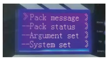
- Main menu page
Press the menu key to enter the main menu page, as shown in the following figure.
- Battery parameter collection page
When the cursor points to“battery parameter acquisition”,press enter to enter the“battery parameter” acquisition page,as shown in the following figure.
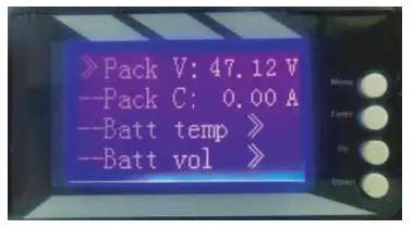
- Battery status page
When the cursor points to“battery state”, press the ENTER button to enter the battery status page,as shown in the following figure.
- Key description
(1) SW1—- MENU, SW2—- ENTER, SW3—-UP, SW4—- DOWN.
(2) Every item will use the“》”or“–” to start,“》”means the current cursor position, press UP or DOWN to move the cursor position up and down. Items ending with “》” indicate that the item has contents not displayed. Press enter to enter the corresponding page.
(3) Press ESC to return to the previous directory. Press the menu key anywhere to return to the main menu page.
(4) In the sleep state, press any key to activate the display screen. - Sleep/Shutdown
In the normal operation state, the system will enter the sleep/shutdown state after 1 minute without key operation. In the sleep state, operate any key and the display screen will be activated. - All date of LCD display

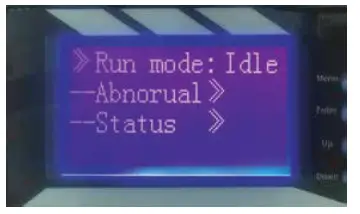
| Pack message》 Pack V: Pack C: “_”: discharging “+”: charging “0”: stand by Battery temp》 Temp1: Temp2: Temp3: Temp4: PCB temp: EV temp: Battery vol》 Vol 01: Vol 02: Vol 16: Battery cap》 SOC: Full Cap: Sur Cap: Cyc Indx: | Pack status》 Run mode: Charging or discharging Abnormal》 Short Num: Temp Pro: Over C Pro: Low V Pro: Over V Num: status》 HT Alarm: HT Pro: HV Alarm: HV Pro: LV Alarm: LV Pro: HC Aarm: HC Pro: Short Pro: Fail Tro: |
Argument tset》 –Not manufacturer. Cannot use. system set》–Baud rate: 9600
Technical parameter list
| Model | 15S100BL | 15S200BL |
| Array Mode | 15S | 15S |
| Nominal Energy (KWh) | 5.0 | 10.0 |
| Nominal Voltage (V) | 48 | 48 |
| Charge Voltage (V) | 54.7 | 54.7 |
| Discharge Cut-off Voltage (V) | 37.5 | 37.5 |
| Standard Charging Current(A) | 20 | 40 |
| Max.Continuous Charging Current (A) | 100 | 100 |
| Max.Continuous Discharging Curent (A) | 100 | 100 |
| Communication Mode | RS485/CAN | RS485/CAN |
| Cycle Life | 6000 times©80°/0DOD, 25°C | |
| Operating Temp | Charge:0-60°C; Discharge: -20°C-65°C | |
| Size(LxWxH) mm | 510x440x170 | 670x440x206 |
| Net Weight (Kg) | 40 | 70 |
| Package Size (LXWXH) mm | 555x500x220 | 730x270x500 |
| Gross Weight (Kg) | 50 | 85 |
Note: The dimensions in the are the product appearance dimensions. If any change for the products, will adjusted by the manufacture.
Maintenance and conservation
| Item | Problem description | Description/possible causes | Solution |
| 1 | Unable to boot properly, BMS will immediately enter the protect ion state after press the switch | The external load does not match.and the instantaneous current of load startup is too large | 1. Press the on key to restart 2. Reduce load power |
| 2 | Automatically disconnect the output during use | 1. The battery voltage is too low 2. Output or load short circuit | 1. Charge the battery 2. Disconnect the load and restart the battery |
| 3 | The Communication fault occurs when the load is inverter | 1. Communication line connection error (connecting pin improper connection or oxidation) 2. The internal protocol code of inverter is not properly chosen 3. Communication insert loose or improper connection | 1. Check the connection between BMS and inverter 2. Choose the corresponding communication protocol in the inverter’s internal program 3. Reconnect the communication cables. If the problem still-exists please contact the manufacturer |
| 4 | |||
| 5 | |||
| 6 |
In order to maintain the best and long-term performance, the following items are recommended to be inspected twice a year.
- Confirm that the surrounding air flow will not be blocked, and remove any dirts and debris on the cooling hole.
- Check all exposed wires, shabby and damage, please place or repair them if necessary.
- If it is not be used for a long time, it is recommended to charge it every three months.
 Danger of electric shock! Make sure that the power supply has been disconnected during the above operations, and then carry out corresponding inspection and operation.
Warranty record card
Dear Customers:
Hello! Thank you very much for purchasing our products. In order to serve you better, please read and fill in and keep this warranty card after purchasing the product. In rder to avoid your worries, our company here by makes a warranty service commitment and provides standardized after sales service accordingly.
Exemption of warranty liability scope:
- Damage caused by man-made or other natural disasters.
- Failure caused by incorrect operation and installation or use in an environment other than the product’s prescribed use.
- Damage caused by unauthorized disassembly and modification.
Contact: ———————
Tel:—————————
Number:——————-
Email:———————-
Purchase date:————
Address:——————-
Maintenance records | |||
| Repair Date | Repair content | Repair Person | |
![]()


