QUICK START GUIDE
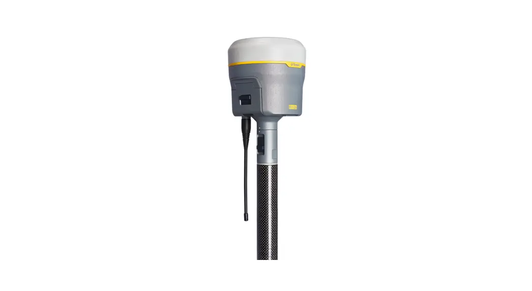
Trimble R12i
GNSS SYSTEM
![]() WARNING – For safety information, refer to the Safety Information section of the Trimble R12i GNSS Receiver User Guide.
WARNING – For safety information, refer to the Safety Information section of the Trimble R12i GNSS Receiver User Guide.
FIVE SIMPLE STEPS TO GET STARTED
This guide provides an overview of the important features and instructions for how to set up and operate the Trimble® R12i GNSS system.
- Unpack and check the contents.
- Charge batteries fully and insert the battery and SIM card into the receiver. Attach the quick release adapter and radio antenna with an SMA connector (receiver models with internal radio only).
- Turn on the receiver.
- Connect to a Trimble controller running the Trimble Access TM field software.
- In the field, collect GNSS data with the Trimble Access field software running on a Trimble controller.
Additional information
For further details regarding the features and operation of the receiver, and to access the latest information, including the Trimble R12i GNSS Receiver User Guide and release notes, go to www.trimble.com.
Trimble R12i support
For Trimble R12i support, go to www.trimble.com/support.
TRANSFORMING THE WAY THE WORLD WORKS
Step 1: Unpacking and checking contents
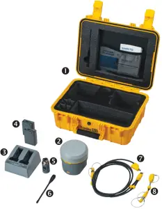
| No. | Description | No. | Description |
| 1 | Transport case (for one receiver) | 5 | Quick-release adapter |
| 2 | Trimble R12i receiver (no internal UHF radio) | 6 | UHF radio antenna with SMA connector (receiver models with internal radio only) |
| 3 | Dual battery charger with battery slot inserts (power supply and power cord kit sold separately) | 7 | USB office data and power Y-cable (7P Lemo-to-USB-A male and power) |
| 4 | Rechargeable Battery (x2) | 8 | USB field data cable (7P Lemo-to-USB-A female) |
| Quick Start Guide (this document) and Trimble Geospatial Accessories Card | Warranty activation card and WEEE statement |
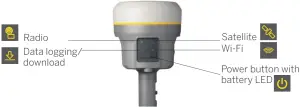
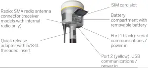
PARTS OF THE TRIMBLE R12i RECEIVER
![]() Tip – Refer to the Trimble Geospatial Accessories Card to learn more about optional Trimble R12i accessories. Alternatively, contact your Trimble distribution partner.
Tip – Refer to the Trimble Geospatial Accessories Card to learn more about optional Trimble R12i accessories. Alternatively, contact your Trimble distribution partner.
All operating controls are located on the front panel. Communication and power Lemo ports and connectors are located on the bottom of the unit.
Front panel
Lower housing
| Icon | Name | Connections |
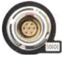 | Port 1 | 7-pin 0-shell Lemo, RS-232, device, computer, external radio, power in, no power out |
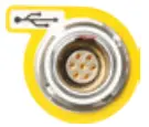 | Port 2 | 7-pin 0-shell Lemo, USB 2.0, device, computer, power in |
Step 2: Charging batteries, inserting battery and SIM card into the receiver, attaching quick release adapter and radio antenna
Charging the Lithium-ion battery
The rechargeable Lithium-ion battery is supplied partially charged. Before using the battery for the first time, charge it completely using the dual-battery
charger (country-specific power supply and power cord kit sold separately). The batteries come with charge battery indicator LEDs. Push the button on the
battery to check the battery charge status.
Charging takes approximately 3 hours at room temperature. If 2 batteries are charging in the dual battery charger, the batteries will be charged simultaneously.
![]() WARNING – Ensure that nothing obstructs the vents in the back of the charger and that the charger is placed on a hard, flat and level surface, to ensure that there is airflow around the charger. Do not operate the battery charger while it is in the transport case.
WARNING – Ensure that nothing obstructs the vents in the back of the charger and that the charger is placed on a hard, flat and level surface, to ensure that there is airflow around the charger. Do not operate the battery charger while it is in the transport case.
LED status indicator

Beside each slot are three LED indicators (red, green, and yellow) to display the battery status:
| Status | Red | Green | Yellow |
| No battery detected (no battery present or battery defect) | On | Off | Off |
Battery detected (charging not started yet)
| 1 Hz 1 Hz | 1 Hz 1 Hz | Off On |
Charging in progress
| Off Off 2 Hz | 1 Hz 1 Hz Off | Off On 2 Hz |
| Conditioning in progress | On | Off | 1 Hz |
| Conditioning did (charging after 30% battery capacity | On | 1 Hz | Off |
| Conditioning did (battery fully charged) | On | On | Off |
Battery fully charged
| Off Off | On On | Off On |
| Power supply over/under voltage | Off | Off | Off |
| When Output Over-Voltage Protection (OVP) or Output Over Current Protection (OCP) is on | 2 Hz+ | Off | Off |
Inserting the battery and SIM card into the receiver
![]() Align the arrows
Align the arrows ![]() and
and ![]() on the battery and battery compartment and then insert the battery as indicated in the picture. To remove the battery, slide the battery bail to the left.
on the battery and battery compartment and then insert the battery as indicated in the picture. To remove the battery, slide the battery bail to the left.![]() Insert the SIM card with the contacts facing upward, as indicated by the SIM card icon
Insert the SIM card with the contacts facing upward, as indicated by the SIM card icon![]() next to the SIM card slot. To eject the SIM card, slightly push it in to trigger the spring-loaded release mechanism.
next to the SIM card slot. To eject the SIM card, slightly push it in to trigger the spring-loaded release mechanism.
![]() Tip – The SIM card is provided by your cellular network service provider.
Tip – The SIM card is provided by your cellular network service provider.
Note: Due to local regulations, the integrated cellular modem cannot be enabled in China, Taiwan, or Brazil. A Trimble controller integrated cellular modem or external cellular modem can be used to obtain GNSS corrections via an IP (Internet Protocol) connection.
Attaching the quick release adapter and radio antenna
![]() Push down the spring-loaded button of the quick release adapter and then align the white dots on the bottom of the receiver and the quick release adapter. Slide in the quick release adapter and then release the button.
Push down the spring-loaded button of the quick release adapter and then align the white dots on the bottom of the receiver and the quick release adapter. Slide in the quick release adapter and then release the button.![]() To install the radio antenna, screw it in clockwise. Do not overtighten!
To install the radio antenna, screw it in clockwise. Do not overtighten!
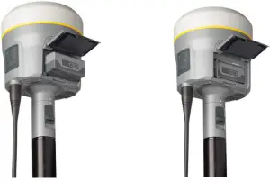
Examples for base and rover configurations
| Postprocessing/RTK base setup | RTK base setup with remote UHF antenna | RTK/Network rover setup |
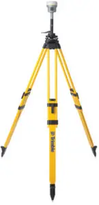 | 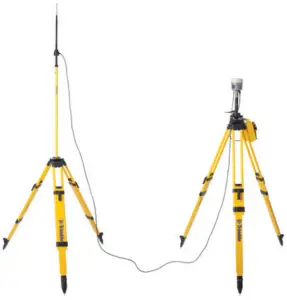 | 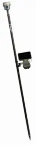 |
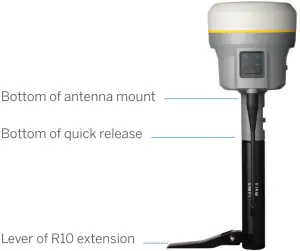
Antenna measurement methods![]() Tip – Optional accessories, such as the base station extension with height measurement lever, tripod, tribrach, external base battery, and remote UHF antenna are available.
Tip – Optional accessories, such as the base station extension with height measurement lever, tripod, tribrach, external base battery, and remote UHF antenna are available.
Step 3: Turning on the receiver
Power button
![]() To turn on the receiver, press the power button. All four LEDs light up, remain lit for 3 seconds, and then turn off. The power LED then immediately lights up again.
To turn on the receiver, press the power button. All four LEDs light up, remain lit for 3 seconds, and then turn off. The power LED then immediately lights up again.![]() To turn off the receiver, hold the power button for 2 seconds and then release it. When holding down the power button, the battery LED remains lit, the satellite LED lights up constantly, and then turns off after 2 seconds. After releasing the power button, the battery LED stays lit for about 5 seconds and then all LEDs turn off.
To turn off the receiver, hold the power button for 2 seconds and then release it. When holding down the power button, the battery LED remains lit, the satellite LED lights up constantly, and then turns off after 2 seconds. After releasing the power button, the battery LED stays lit for about 5 seconds and then all LEDs turn off.![]() To clear the ephemeris file and reset the receiver to the factory defaults, hold down the power button for 15 seconds. The radio, Wi-Fi, and satellite LEDs turn off after 2 seconds but the battery LED remains lit. After 15 seconds, the satellite LED lights up to indicate that it is time to release the power button.
To clear the ephemeris file and reset the receiver to the factory defaults, hold down the power button for 15 seconds. The radio, Wi-Fi, and satellite LEDs turn off after 2 seconds but the battery LED remains lit. After 15 seconds, the satellite LED lights up to indicate that it is time to release the power button.
![]() CAUTION – Resetting the receiver will permanently erase all data. Download your data before resetting your receiver.
CAUTION – Resetting the receiver will permanently erase all data. Download your data before resetting your receiver.
To delete application files, hold down the power button for 30 seconds. The radio, Wi-Fi, and satellite LEDs turn off after 2 seconds but the battery LED remains lit. After 15 seconds, the satellite LED lights up and remains lit for 15 seconds, then turns off to indicate that it is time to release the power button. The battery LED remains lit for 15 seconds after you release the Power button. The receiver then restarts
![]() Battery LED
Battery LED
| Receiver mode | Power LED | Description |
| Off | Off | |
| On, healthy power | On | Either internal battery or external power |
| Low power | Fast flash | Less than about 15% power |
![]() Satellite LED
Satellite LED
| Receiver mode | Satellite LED |
| No satellite tracked | Off |
| Boot up or in monitor mode | On |
| Tracking fewer than 4 satellites | Fast flash |
| Tracking more than 4 satellites | Slow flash |
![]() Radio LED
Radio LED
| Radio mode | Radio LED | Description |
| No, receive or transmit | Off | |
| Receive | Radio slow flash | This LED also flashes when using the Wi-Fi only for receiving corrections. |
| Transmit | Radio slow flash | This LED also flashes when using the Wi-Fi only for transmitting corrections |
![]() Wi-Fi LED
Wi-Fi LED
| Receiver mode | Wi-Fi LED |
| Wi-Fi off | Off |
| Wi-Fi is an access point (base mode/sending corrections) | Medium flash |
| Wi-Fi is the client (and not connected to an access point) | Off |
| Wi-Fi as a client (rover mode receiving corrections) | Very slow flash |
![]() Data logging/downloading LED
Data logging/downloading LED
| Receiver mode | Data LED |
| Data logging off | Off |
| Data logging on | On |
| Downloading to USB Flash memory stick | Slow flash |
| Full USB Flash memory stick detected | Fast flash |
| Download to USB complete | Very slow flash |
Step 4: Connecting to a Trimble controller running the Trimble Access field software
The Trimble R12i receiver can communicate with any controller—for example, a Trimble TSC7 controller—that is running Trimble Access software (version 2020.10 or later) using Bluetooth® wireless technology. If you do need a cable, refer to the Trimble R12i GNSS Receiver User Guide for a list of all available cables for the receiver.
![]() Tip – To learn more about Bluetooth connections to a Trimble R Series receiver, refer to the Trimble Access help portal at
Tip – To learn more about Bluetooth connections to a Trimble R Series receiver, refer to the Trimble Access help portal at
https://help.trimblegeospatial.com/TrimbleAccess.
Step 5: Collecting GNSS data with Trimble Access field software on a Trimble controller in the field
The Trimble R12i system with Trimble Access field software is now ready to be used. Refer to the Trimble Access help portal for more information.
Aligning the system
The Trimble R12i has an integrated Inertial Measurement Unit (IMU) comprising multiple sensors that detect relative motion. Data from the IMU and GNSS signal measurements are combined by the positioning engine to compute the position (XYZ) and attitude (roll, pitch, and azimuth) of the receiver, allowing the pole tip position to be determined when the rover is tilted. You do not need to perform any specific calibration steps to align the IMU with the GNSS reference frame, and the system is unaffected by sources of magnetic interference.
To achieve a combined GNSS and inertial solution:
- Begin a Real-Time Kinematic survey with corrections from a base station, VRS network, or Trimble CenterPoint RTX.
- Enter the antenna height in Trimble Access.
- Introduce some motion to the system, which may include tilting the pole in orthogonal directions. Trimble Access will report an “RTK+IMU” solution type along with the estimated horizontal and vertical precision once the solution has aligned. For more information, refer to the Trimble Access help portal.
Connecting to the office computer
To communicate with the office computer using a serial connection, you can either connect the receiver using a serial cable (P/N 89851-00 or P/N
59046), or by using the USB cable (P/N 89852-00 or P/N 80751) and then configuring a computer USB port as a virtual serial port.
Before you connect to the office computer, ensure that the receiver battery is fully charged.
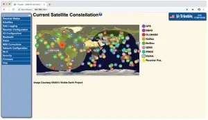
Connecting to the receiver web interface
- Turn on the receiver and wait for the last four digits of the receiver serial number to appear under the available Wi-Fi networks on your smartphone or office computer. For example, Trimble GNSS XXXX (where XXXX represents the last four digits of the receiver serial number).
- Select the receiver, open a web browser and then enter the following IP address: http://192.168.142.1
The default login values for the receiver are as follows:
User Name: admin
Password: password
![]() Tip – Most web browsers for computers/laptops and smartphones support the receiver web interface.
Tip – Most web browsers for computers/laptops and smartphones support the receiver web interface.

Use of the Made for Apple badge means that an accessory has been designed to connect specifically to the Apple product(s) identified in the badge and
has been certified by the developer to meet Apple performance standards. Apple is not responsible for the operation of this device or its compliance with
safety and regulatory standards. Apple, iPad, and iPhone are trademarks of Apple Inc., registered in the U.S. and other countries.

Google, Google Play, and other marks are trademarks of Google LLC.
© 2020. Trimble Inc. All rights reserved. This product is protected by the US and international copyright, trademark, and patent law as described in “Legal Notices” in the product documentation. Version 1.00, Revision A (September 2020). Parts of this product are patent protected. Trimble has relied on representations made by its suppliers in certifying this product is RoHS compliant. Specifications are subject to change without notice. Trimble Inc. is not responsible for the operation or failure of the operation of GNSS satellites or the availability of GNSS satellite signals. Revision A. P/N 89907-00-ENG
![]()
![]()
Trimble Inc.
10368 Westmoor Drive
Westminster CO 80021
USA


