Singular XYZ SAGRO10 GNSS Guidance System
Proprietary Notice
- Information in this document is subject to change without notice and does not represent a commitment on the part of SingularXYZ Intelligent Technology Ltd. The software described in this document is furnished under a license agreement or non-disclosure agreement. The software may be used or copied only in accordance with the terms of the agreement. It is against the law to copy the software on any medium except as specifically allowed in the license or non-disclosure agreement.
- No part of this manual may be reproduced or transmitted in any form or by any means, electronic or mechanical, including photocopying and recording, for any purpose without the express written permission of a duly authorized representative of SingularXYZ Intelligent Technology Ltd.
Corporate Office
- Singular XYZ Intelligent Technology Ltd.
- Address: Floor 2, Building A, No. 599 Gaojing Road, 201702 Shanghai, China Tel: +86-21-60835489
- Fax: +86-21-60835497
- Website: https://www.singularxyz.com
- E-mail: [email protected]
Technical Assistant
If you have any questions that can’t be solved in this manual, please contact your local SingularXYZ distribution partner. Alternatively, request technical support from SingularXYZ Intelligent Technology Ltd.
- Support Email: [email protected]
- Support Skype: Support.SingularXYZ
Your feedback on this manual will help us improve it with future revisions.
©2021 SingularXYZ Intelligent Technology Ltd. All rights reserved.
INTRODUCTION
Overview
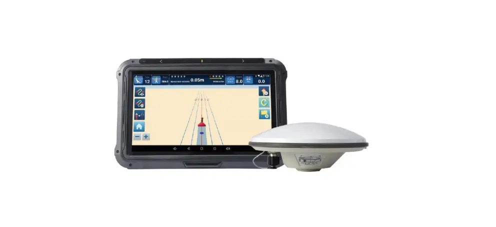
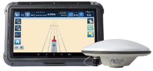
- The SAgro10 guidance system consists of a tablet integrated with a high-precision GNSS module, a geodetic antenna and the guidance software that can intelligently manage the working field and simplify the operation of users, including the recording of the completed work area, the planning and navigation of the work route, etc., which greatly reduces manual mistakes and improves work efficiency. It can be widely used for sowing, cultivating, trenching, ridging, spraying pesticide, transplanting, land consolidation, harvesting and other work scenarios.
- The SAgro10 guidance system is compatible with most agricultural tractors, and all components can be easily installed within 20 minutes. Moreover, the SAgro10 guidance system can be easily upgraded to an auto-steering system. On the basis of keeping all components unchanged, only need to add a SEM1(Singular XYZ Electric Motor) to the SAgro10 guidance system to easily upgrade it to auto-steering system, freeing users’ hands and improving work efficiency.
- This manual will introduce how to install and how to use the SAgro10 guidance system.
System Composition
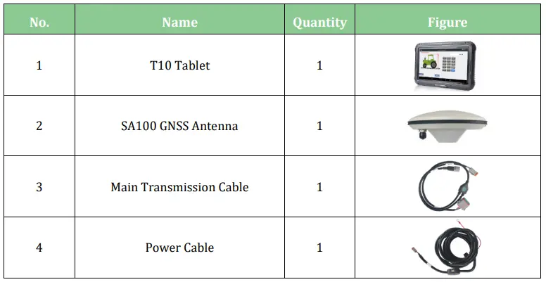
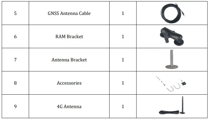
The SAgro10 guidance system mainly includes one T10 Control Tablet and one SA100 GNSS antenna. The detailed packing list is shown in the table below.
Table 1: Packing list of SAgro10 automated steering system
EQUIPMENT ASSEMBLY
This chapter introduces how to install the SAgro10 system.
Antenna Installation
When installing the SA100 GNSS antenna, it needs to be installed on the centerline on the top of the tractor.
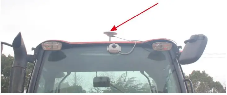 Figure 2.1 Antenna installation-1
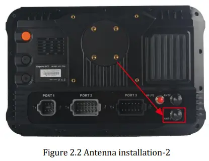
The SA100 GNSS antenna should be connected to the GNSS connector (ANT1) on the back of the T10 tablet via a GNSS antenna cable.
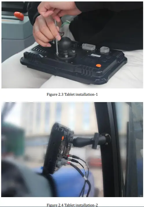
Tablet Installation
The T10 tablet should be installed in the driver cab of the tractor on the RAM bracket, which is shown as
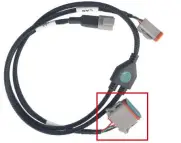
Cable Installation
The cable connection is shown in the figures below.
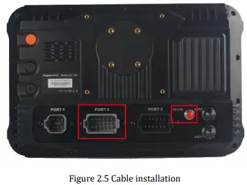
- The 4G antenna is connected to the 4G connector on the right side of the T10 tablet back.
- The main transmission cable should be connected to PORT 2 on the back of the T10 tablet.

- The power cable are connected to the main transmission cable, which has Power label on it.
- The power supply cable should connect to the vehicle battery. (Support both 12V and 24V)
SYSTEM OPERATION
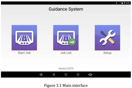
Main Interface
For the SAgro10 guidance software, there are 3 main interfaces including Start Job, Job List and Setup interface.
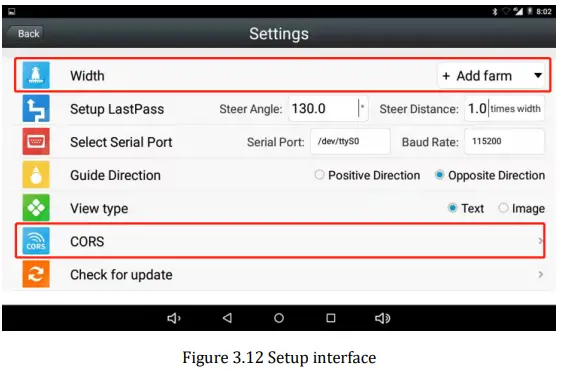
 Setup Interface
Before starting the guidance task, please setup the related settings first.
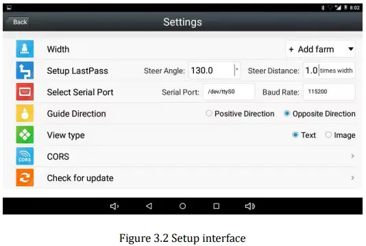
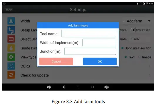
- Width

Click to add or delete farm tools, including the width and joint width setting.
- Last Pass

Parameters of “LastPass” redirection, please keep the default parameters. - Guide Direction

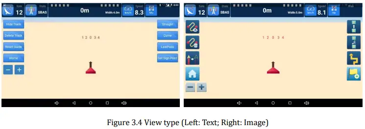
Set whether the guide arrow in Start Job interface is points to the heading direction or deviates from the direction. - View Type

Set the menu display of Start Job interface.
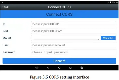
- CORS

Set the CORS account, including the IP, port, mount point, username and passwords.
Start Job Interface
After configuration setup, users can conduct the guidance task in Start Job interface, which is shown in the figure below.
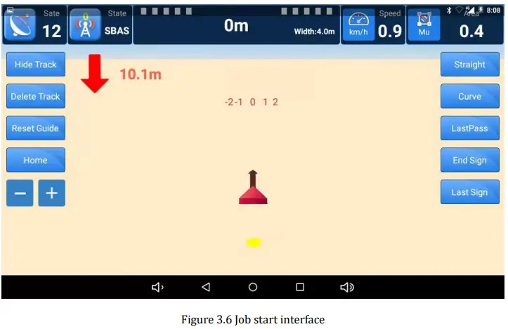
Top Status Bar
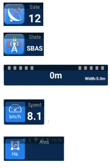
- Number of tracking satellites.
- Differential Status, including SBAS, RTK or Smooth during normal operation.
- Deviation distance (unit: meter) in the middle, width setting on the right side.
- Current speed of the tractor (unit: km/h).
- Area of completed operation.
Left Toolbar
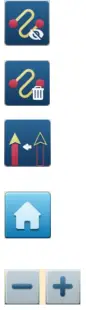
- Hide track: Click to hide/show the tractor track.
- Delete track: Click to delete current track.
- Reset track: Click to reset the AB line at the current tractor location.
- Home: Click to return main interface.
- Click to zoom in and zoom out the operating interface.
Operation buttons
On the right side of Start Job interface, you can select work modes and start job.
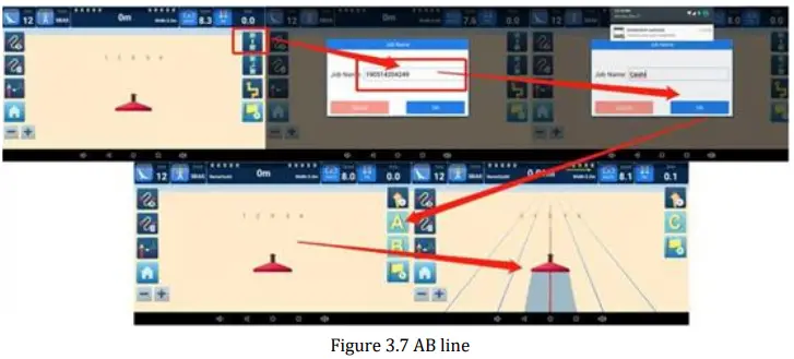
 Straight line work mode, including:
- AB line and ABC line.1)AB line: Click Set A and Set B in turn to set point A and B, the straight guidance lines will be generated based onAB two points.

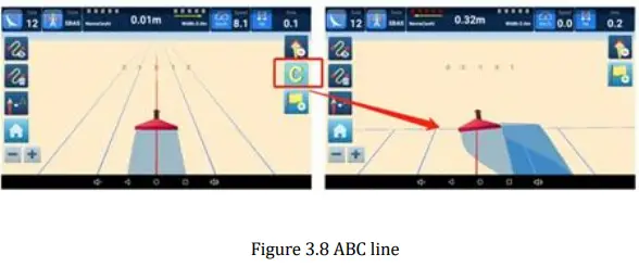
- ABC line: After setting AB line, click Set C when the tractor reaches the boundary. The boundary will be generated based on point C.

- AB line and ABC line.1)AB line: Click Set A and Set B in turn to set point A and B, the straight guidance lines will be generated based onAB two points.
 AB Curve work mode.
Click Set A and Set B in turn to set point A and B, the guidance curve will be generated according to the trajectory between points AB.
 Last Pass: Generate the AB line for the next trip according to the trajectory of the previous trip.
 Set Sign Point: Guide the user toward the guidance point according to the set guidance point.
 AB Curve work mode.
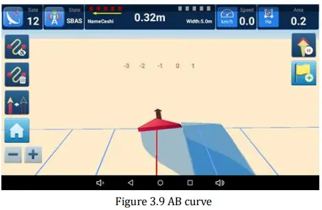
 Last Pass: Generate the AB line for the next trip according to the trajectory of the previous trip.
 Set Sign Point: Guide the user toward the guidance point according to the set guidance point.
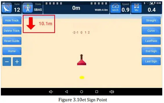
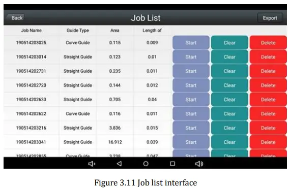
Job List Interface
All guidance job information of is saved in the job list interface
Work Flow
After system installation, you can start your work tasks according to the following steps.
System Setting
Set the farm tools and the width in Setup >> Width, refer to chapter 3.2 – 1.
Note:
- The default GNSS navigation mode is single-point smooth positioning. If you have additional requirements for higher positioning accuracy, the RTK positioning mode is also available in SAgro10 system.
- Go to Setup interface, connect to the CORS by entering and applying your CORS account, the detailed instructions please refer to chapter 3.2 – 5.
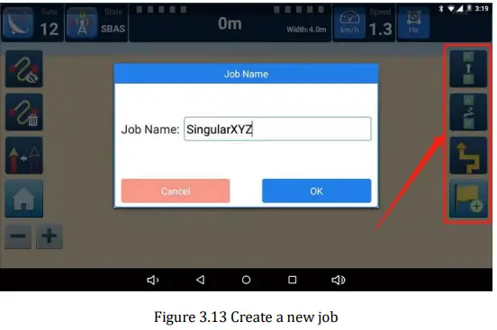
Create A New Task
- After configuration, go to Start Job interface and select your working mode on the right side, which includes Straight line, Curve, Last Path and Set sign point 4 modes. The detailed instructions about each work mode please refer to chapter 3.3.3.
- The prompt box for creating a new job will pop up after selecting the work mode, as shown in Figure 3.13. You can start your navigation task after creating tasks.

APPENDIX
Datasheet
T10 GNSS Tablet
Table 2: T10 Datasheet
| System | |
| Operation System | Android 6.0 |
| CPU | Quad-Core 1.5GHZ |
| RAM | 2GB |
| ROM | 16GB |
| Flash | T flash, up to 64GB |
| Display | |
| LCD | 10.1″ HD |
| Brightness | 750Nits, sunlight readable |
| Resolution | 1024×600 pixels |
| Touch Panel | Capacitive screen |
| GNSS Specifications | |
| GPS | L1, L2 |
| GLONASS | L1, L2 |
| BDS | B1, B2 |
| Galileo | E1, E5b |
| QZSS | L1, L5 |
| SBAS | WAAS, EGNOS, MSAS, GAGAN |
| RTK Accuracy | H: 10mm+1ppm, V: 15mm+1ppm |
| Heading Accuracy | 0.1° |
| Timing Accuracy | 20ns |
| Velocity Accuracy | 0.03m/s |
| Data Format | RTCM 2.3/3.0/3.2, NMEA0183 |
| Data Update Rate | Maximum 20Hz |
| Electrical & Physical | |
| Signal Tracking | |
| GPS | L1, L2, L5 |
| GLONASS | L1, L2 |
| BeiDou | B1, B2, B3 |
| Galileo | E1, E5a/E5b, AltBoc |
| SBAS | + |
| L-Band | + |
| LNA | |
| Impedance | 50 Ohm |
| Polarization | RHCP |
| Axial Ratio | ≤3dB |
| Azimuth Coverage | 360° |
| Gain at Zenith | 5.5dBi |
| Phase Center Accuracy | ±2mm |
| LNA Gain | 40dB |
| Noise Figure | ≤2dB |
| VSWR Output | ≤2.0 |
| Operation Voltage | 3 – 18VDC |
SA100 GNSS Antenna
Table 3: SA100 GNSS Antenna
| Signal Tracking | |
| GPS | L1, L2, L5 |
| GLONASS | L1, L2 |
| BeiDou | B1, B2, B3 |
| Galileo | E1, E5a/E5b, AltBoc |
| SBAS | + |
| L-Band | + |
| LNA | |
| Impedance | 50 Ohm |
| Polarization | RHCP |
| Axial Ratio | ≤3dB |
| Azimuth Coverage | 360° |
| Gain at Zenith | 5.5dBi |
| Phase Center Accuracy | ±2mm |
| LNA Gain | 40dB |
| Noise Figure | ≤2dB |
| VSWR Output | ≤2.0 |
| Operation Voltage | 3 – 18VDC |
| Operation Current | ≤45mA |
| Ripple | ±1dB |
| Group Delay | <5ns |
| Physical | |
| Dimension | Φ152×62.2mm |
| Connector | TNC Female |
| Weight | 374g |
| Mounting Configuration | 5/8″x 11 Threaded |
| Environmental | |
| Operating Temperature | -40℃ to +85℃ |
| Environmentally Sealed Type | IP67 |
| Humidity | 95% No-condensing |


