DEWALT UltraCon SS4 410 Stainless Steel Screw Anchor
GENERAL INFORMATION
PRODUCT DESCRIPTION
The UltraCon SS4 anchor is a 410 stainless steel screw anchor for light to medium duty applications in concrete and masonry block base materials. The screw anchor is fast and easy to install and provides a neat, finished appearance. UltraCon SS4 anchors feature a Stalgard coating and provide enhanced corrosion resistance over carbon steel fasteners.
GENERAL APPLICATIONS AND USES
- Screen Enclosures
- Storm Shutters
- Light Duty Fixtures
- Light Duty Industrial Mounts
FEATURES AND BENEFITS
+ Special heat treatment to protect inherent corrosion resistance of the 410 stainless steel material
+ Stalgard coating provides 1000 hours of salt spray protection when tested in accordance with ASTM B117
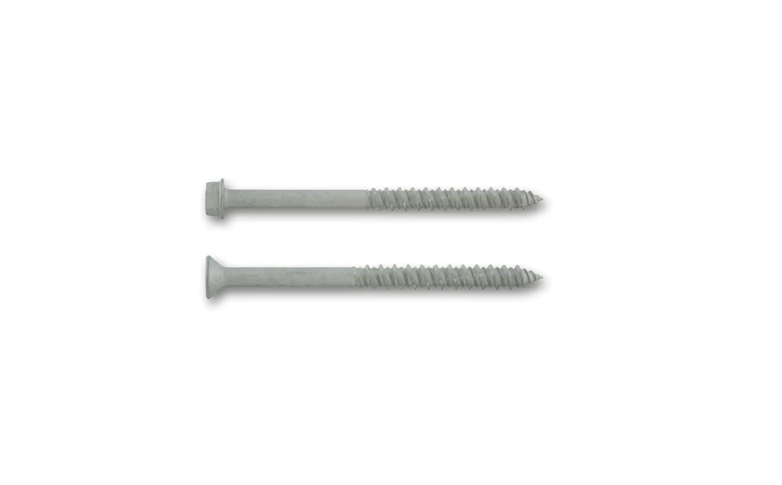
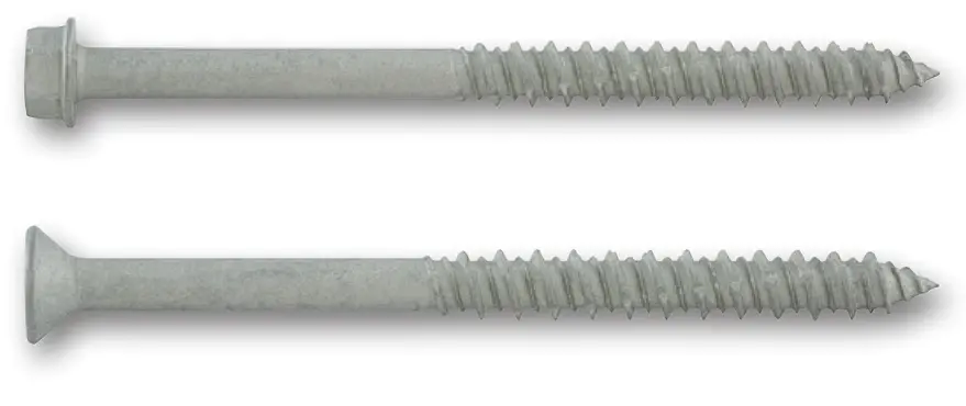
HEAD STYLES
- Hex Washer Head
- TrimFit® Flat Head
ANCHOR MATERIALS
- Type 410 Stainless Steel with Stalgard® Coating
ANCHOR SIZE RANGE
- 1/4″ diameter x 1-1/4″ to 6″ lengths
SUITABLE BASE MATERIALS
- Normal-Weight Concrete
- Hollow Concrete Masonry (CMU)
- Grout-Filled Concrete Masonry (CMU)
APPROVALS AND LISTINGS
- Tested in accordance with ASTM E488
- Miami-Dade County Notice of Acceptance (NOA) No. 21-0201.08
- Florida Statewide Product Approval FL29068.1
GUIDE SPECIFICATIONS
CSI Divisions: 03 16 00 – Concrete Anchors, 04 05 19.16 – Masonry Anchors and 05 05 19 – PostInstalled Concrete Anchors. Screw anchors shall be UltraCon SS4 as supplied by DEWALT, Towson, MD. Concrete screw anchors shall be installed in accordance with published instructions and the Authority Having Jurisdiction.
MATERIAL SPECIFICATIONS
Anchor Component | Specification |
Anchor body | 410 stainless steel |
Coating/Plating/Finish | stalgard® 1000 hour rating per AsTM b117 salt spray test |
| Note: 410 stainless steel fasteners in contact with aluminum and aluminum alloys is not recommended in accordance with AIsI ss 502 / ssINA guidelines. | |
INSTALLATION SPECIFICATIONS
Anchor Property / Setting Information | Notation | Anchor Diameter, da | |
| 1/4″ HEX | 1/4″ TFH | ||
| Anchor shank Diameter (in) | da | 0.193 | 0.193 |
| Ultracon+ Drill bit size (in) | dbit | 3/16 | 3/16 |
| Typ. Fixture Clearance hole (in) | dh | 5/16 | 5/16 |
| Head Height (in) | – | 9/64 | 3/16 |
| Head Width (in) | – | 5/16 | 13/32 |
| Washer o.D. (in) | – | 13/32 | N/A |
| Washer Thickness (in) | – | 1/32 | N/A |
| Hex Driver (in) / Phillips Driver | – | 5/16 | #3 |
| 1. For minimum nominal embedment depths, hnom, see the performance data tables. The minimum hole depth, ho, is 1/4-inch more than the selected nominal embedment depth. | |||
410 Stainless Steel UltraCon SS4 Identification
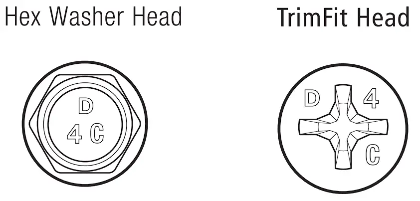
The head markings consist of a “D” for the DEWALT brand, the number “4” for the 410 series stainless steel classification, and the length code
UltraCon SS4 Length Code Identification System
Length ID marking on head | A | B | C | D | E | F | G | H | ||
overall anchor length ℓanch (inches) | From | 1″ | 1-1/2″ | 2″ | 2-1/2″ | 3″ | 3-1/2″ | 4″ | 4-1/2″ | 5-1/2″ |
| Up to but not including | 1-1/2″ | 2″ | 2-1/2″ | 3″ | 3-1/2″ | 4″ | 4-1/2″ | 5-1/2″ | 6-1/2″ | |
Anchor Detail
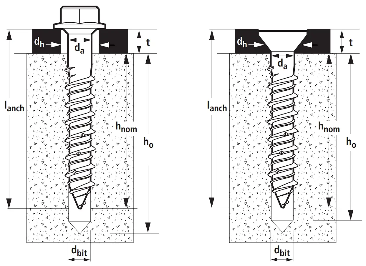
Nomenclature
da = Diameter of anchor
dbit = Diameter of drill bit
dh = Diameter of fixture clearance hole
hnom = Minimum embedment depth
h = Base material thickness
The minimum value of h should be 1.5hnom or 3″ whichever is greater
ho = Minimum hole depth
INSTALLATION INSTRUCTIONS
Installation Instruction for UltraCon SS4
Step 1
Using the proper drill bit size, drill a hole into the base material to the required depth, ho, which is a 1/4-inch deeper than the minimum embedment depth, hnom.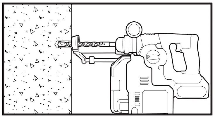
Step 2
Remove dust and debris from the hole during drilling (e.g. dust extractor) or following drilling (e.g. suction, forced air) to extract loose particles created by drilling.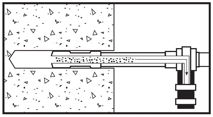
Step 3
Attach a UltraCon+ installation socket tool for the selected anchor size to a percussion drill and set the drill to rotary only mode. Mount the screw anchor head into the socket. For flat head versions a bit tip must be used with the socket tool.
Step 4
Place the point of the UltraCon SS4 through the fixture into the pre-drilled hole and drive the anchor in one steady continuous motion until it is fully seated at the proper embedment. The driver will automatically disengage from the head of the screw.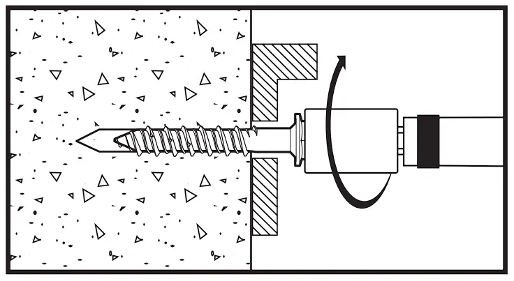
PERFORMANCE DATA
Ultimate Load Capacities for UltraCon SS4 in Normal-Weight Concrete1
| Nominal Anchor Diameter | Min. Edge Dist. (in.) | Min. Spacing (in.) | Min. Embed. (in.) | Minimum Concrete Compressive Strength | |||
| 2500 psi | 3000 psi | ||||||
| Tension (lbs.) | Shear (lbs.) | Tension (lbs.) | Shear (lbs.) | ||||
| 1/4 | 1 | 1-1/2 | 1-1/2″ | 340 | 265 | 365 | 280 |
| 1-3/4″ | 540 | 385 | 580 | 410 | |||
| 3 | 1-1/2″ | 610 | 275 | 660 | 295 | ||
| 1-3/4″ | 1235 | 510 | 1330 | 540 | |||
| 2-1/2 | 1-1/2 | 1-1/2″ | 720 | 730 | 770 | 775 | |
| 1-3/4″ | 1275 | 1900 | 1375 | 2020 | |||
| 3 | 1-1/2″ | 885 | 990 | 955 | 1050 | ||
| 1-3/4″ | 1515 | 2200 | 1630 | 2335 | |||
| |||||||
Allowable Load Capacities for UltraCon SS4 in Normal-Weight Concrete1
| Nominal Anchor Diameter | Min. Edge Dist. (in.) | Min. Spacing (in.) | Min. Embed. (in.) | Minimum Concrete Compressive Strength | |||
| 2500 psi | 3000 psi | ||||||
| Tension (lbs.) | Shear (lbs.) | Tension (lbs.) | Shear (lbs.) | ||||
| 1/4 | 1 | 1-1/2 | 1-1/2″ | 85 | 65 | 90 | 70 |
| 1-3/4″ | 135 | 95 | 145 | 100 | |||
| 3 | 1-1/2″ | 150 | 65 | 165 | 70 | ||
| 1-3/4″ | 305 | 125 | 330 | 135 | |||
| 2-1/2 | 1-1/2 | 1-1/2″ | 180 | 180 | 190 | 190 | |
| 1-3/4″ | 315 | 475 | 340 | 505 | |||
| 3 | 1-1/2″ | 220 | 245 | 235 | 260 | ||
| 1-3/4″ | 375 | 550 | 405 | 580 | |||
| |||||||
Ultimate Load Capacities for UltraCon SS4 in Hollow and Grout-Filled Concrete Masonry1,2
| Nominal Anchor Diameter (in.) | Min. Edge Dist. (in.) | Min. Spacing (in.) | Min. Embed. (in.) | Hollow Bock | Grout-Filled Block | ||
| Tension (lbs.) | Shear (lbs.) | Tension (lbs.) | Shear (lbs.) | ||||
| 1/4 | 1 | 1-1/2 | 1-1/4 | 530 | 220 | 685 | 280 |
| 2 | – | – | 1090 | 280 | |||
| 3 | 1-1/4 | 620 | 360 | 950 | 415 | ||
| 2 | – | – | 1460 | 415 | |||
| 2-1/2 | 1-1/2 | 1-1/4 | 530 | 445 | 1025 | 455 | |
| 2 | – | – | 1090 | 900 | |||
| 3 | 1-1/4 | 620 | 615 | 1060 | 1000 | ||
| 2 | – | – | 1930 | 1510 | |||
| |||||||
Allowable Load Capacities for UltraCon SS4 in Hollow and Grout-Filled Concrete Masonry1
| Nominal Anchor Diameter (in.) | Min. Edge Dist. (in.) | Min. Spacing (in.) | Min. Embed. (in.) | Hollow Bock | Grout-Filled Block | ||
| Tension (lbs.) | Shear (lbs.) | Tension (lbs.) | Shear (lbs.) | ||||
| 1/4 | 1 | 1-1/2 | 1-1/4 | 105 | 40 | 135 | 55 |
| 2 | – | – | 215 | 55 | |||
| 3 | 1-1/4 | 120 | 70 | 190 | 80 | ||
| 2 | – | – | 290 | 80 | |||
| 2-1/2 | 1-1/2 | 1-1/4 | 105 | 85 | 205 | 90 | |
| 2 | – | – | 215 | 180 | |||
| 3 | 1-1/4 | 120 | 120 | 210 | 200 | ||
| 2 | – | – | 385 | 300 | |||
| |||||||
ORDERING INFORMATION
Silver Stalgard® UltraCon SS4
| Cat. No. | Screw Size | Approximate Thread Length | Pack Qty. | Carton Qty. | |
| HWH | TFH | ||||
| DFM4EUH310 | DFM4EUF310 | 1/4″ X 1-1/4″ | 1-1/8″ | 100 | 500 |
| DFM4EUH315 | DFM4EUF315 | 1/4″ X 1-3/4″ | 1-5/8″ | 100 | 500 |
| DFM4EUH325 | DFM4EUF325 | 1/4″ X 2-1/4″ | 1-7/8″ | 100 | 500 |
| DFM4EUH335 | DFM4EUF335 | 1/4″ X 2-3/4″ | 1-7/8″ | 100 | 500 |
| DFM4EUH345 | DFM4EUF345 | 1/4″ X 3-1/4″ | 1-7/8″ | 100 | 500 |
| DFM4EUH355 | DFM4EUF355 | 1/4″ X 3-3/4″ | 1-7/8″ | 100 | 500 |
| DFM4EUH365 | DFM4EUF365 | 1/4″ X 4″ | 1-7/8″ | 100 | 500 |
| DFM4EUH375 | – | 1/4″ X 5″ | 1-7/8″ | 100 | 500 |
| DFM4EUH385 | – | 1/4″ X 6″ | 1-7/8″ | 100 | 500 |
| HWH = Hex Washer Head, TFH = TrimFit® Flat Head Hex Head UltraCon ss4 Anchors are measured from below the washer while flat head UltraCon ss4 anchors are measured end to end. To select the proper minimum anchor length, determine the embedment depth required (e.g. required to obtain desired load capacity). Then add the thickness of the fixture, including any spacers or shims, to the embedment depth. | |||||
UltraCon+ Drill Bits
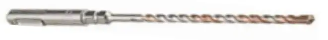
| Cat. No. | Description |
| DW5382 | 3/16 x 7″ UltraCon+ sDs bit |
Installation Kit
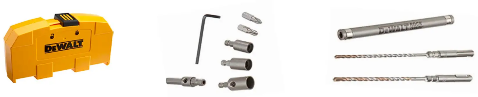
| Cat. No. | Description |
| DW5366 | UltraCon®+ Installation Kit includes: 5/32″ and 3/16″ UltraCon+ bit, 1/4″ and 5/16″ nutsetters, #2 and #3 Phillips bits, Phillips flat head adapter, percussion adapter, drive sleeve and 1/8″ allen wrench |
Rotary Hammers
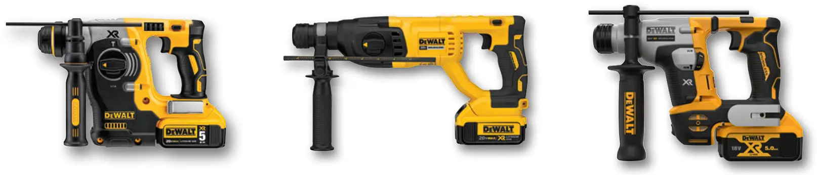
| Cat. No. | Description |
| DCH273 | 20V Max* Xr brushless 1″ L-shape sDs Plus rotary Hammer |
| DCH133 | 20V Max* Xr brushless 1″ D-Handle sDs Plus rotary Hammer |
| DCH172 | AToMIC 20V MAX 5/8 in. brushless Cordless sDs Plus rotary Hammer |
Accessories
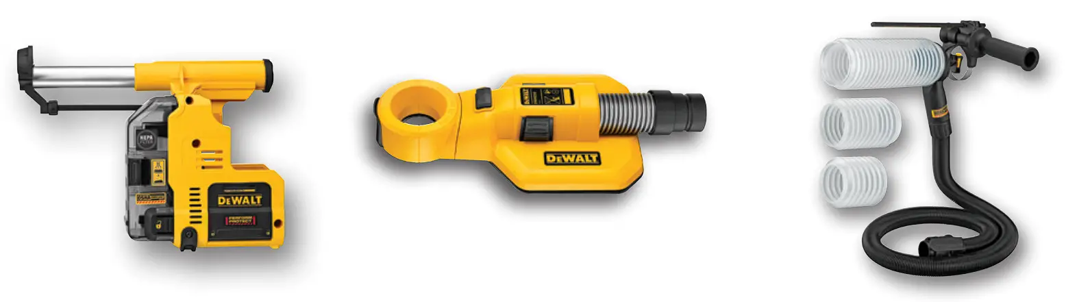
| Cat. No. | Description |
| DWH303DH | onboard Dust Extractor for 1″ sDs Plus Hammers |
| DWH050 | Large Hammer Dust Extraction – Hole Cleaning |
| DWH200 | Dust Extraction Tube Kit with Hose |
Dust Extractors
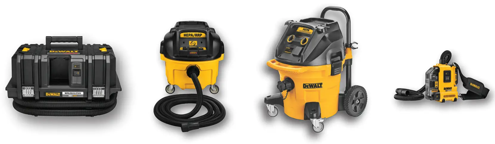
| Cat. No. | Description |
| DCV585 | Flexvolt® 60V Max* Dust Extractor |
| DVW010 | 8 Gallon Wet Dry Hepa/rrp Dust Extractor |
| DWV012 | 10 Gallon Wet Dry Hepa/rrp Dust Extractor |
| DWH161D1 | 20V Max* Xr brushless Universal Dust Extractor Kit |


 M10 Wedge Anchor Instruction Manual")


