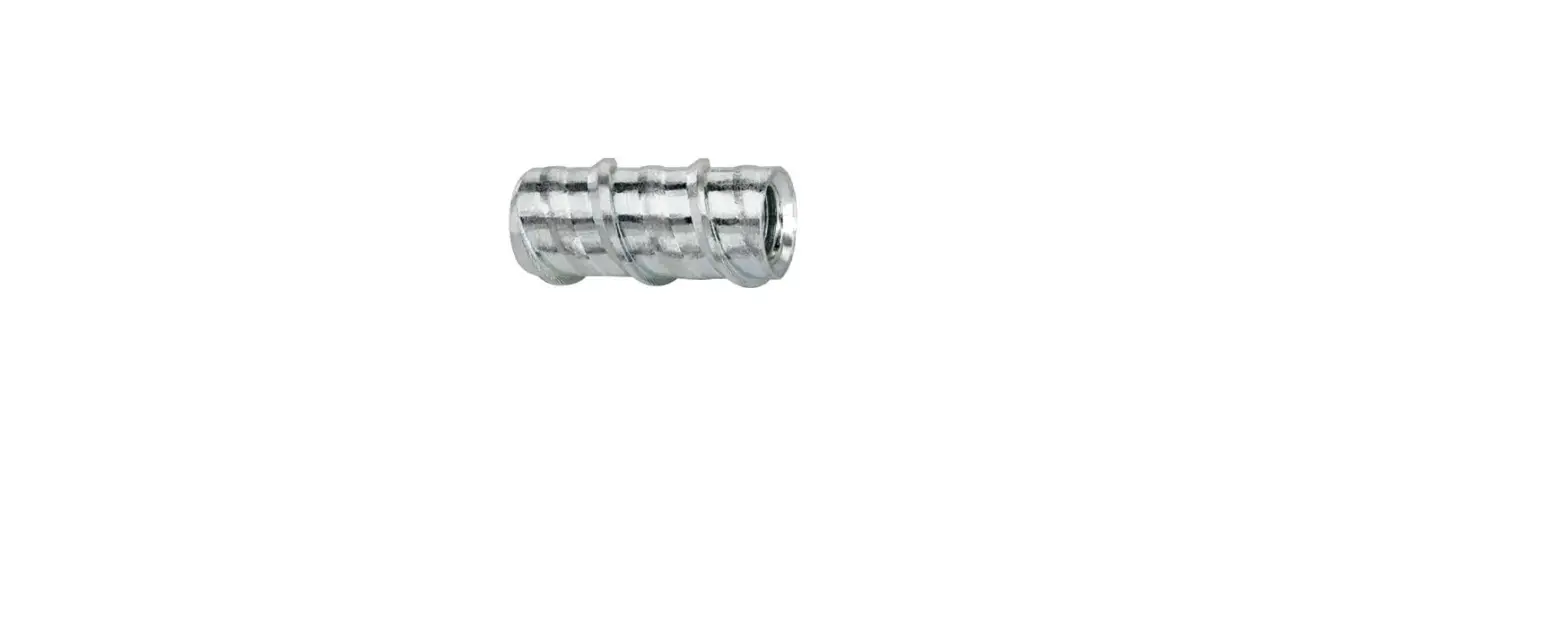
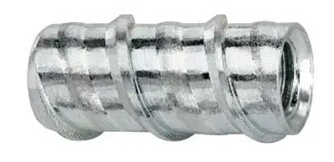
DEWALT SNAKE+ Internally Threaded Screw Anchor
PRODUCT DESCRIPTION
The snake+ anchor is an internally threaded, self-tapping screw anchor designed for performance in cracked and uncracked concrete. suitable base materials include normal-weight concrete, lightweight concrete and concrete over steel deck. The snake+ screw anchor is installed into a drilled hole with a power tool and a snake+ setting tool. After installation a steel element is threaded into the anchor body.
GENERAL APPLICATIONS AND USES
- Suspending conduit, cable trays and strut
- Interior low level corrosion environment
- Tension zone / cracked concrete
- Seismic attachments (SDC A – F)
- Fire sprinklers and pipe supports
- Suspended lighting
FEATURE AND BENEFITS
- Cracked concrete approved alternative to a dropin anchor
- Designed for use in holes drilled with standard ANSI carbide drill bits
- Anchor design allows for shallow embedment and mechanically interlocks with base material
- Internally threaded anchor for easy adjustment and removability of threaded rod or bolt
- Fast anchor installation with a powered impact wrench
- Hammer not used for installation
APPROVALS AND LISTINGS
- International Code Council, Evaluation Service (ICC-ES), ESR-2272 for concrete; code compliant with the 2021 IBC/IRC, 2018 IBC/IRC, 2015 IBC/IRC and 2012 IBC/IRC.
- Tested in accordance with ACI 355.2 and ICC-ES AC193 for use in concrete under the design provisions of ACI 318 (-19 and -14) Chapter 17 or ACI 318-11 (Appendix D)
- Evaluated and qualified by an accredited independent testing laboratory for recognition in cracked and uncracked concrete including seismic and wind loading (anchor Category 1)
- Evaluated and qualified by an accredited independent testing laboratory for reliability against brittle failure, e.g. hydrogen embrittlement
- Evaluated and qualified by an accredited independent testing laboratory for supplemental recognition in redundant fastening applications
- FM Global (Factory Mutual) – 3/8″ diameter, see FM Approval Guide Pipe hanger components for automatic sprinkler systems
GUIDE SPECIFICATIONS
CSI Divisions: 03 16 00 – Concrete Anchors and 05 05 09 – Post-Installed Concrete Anchors.
Internally threaded anchors shall be Snake+ as supplied by DEWALT, Towson, MD. Anchors shall be installed in accordance with published instructions and the Authority Having Jurisdiction.
MATERIAL SPECIFICATIONS
| Anchor Component | Specification |
| Anchor Body | Case hardened carbon steel |
| Plating | Zinc plating according to AsTM B633, sC1, Type III (Fe/Zn 5) Minimum plating requirements for Mild service Condition |
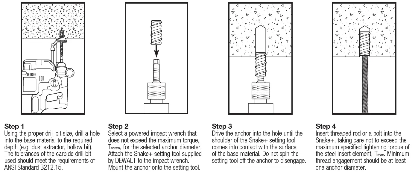
INSTALLATION SPECIFICATIONS
Installation Information for Snake+ Screw Anchor1
| Anchor Property/ Setting Information | Notation | Units | Nominal Anchor Size / Threaded Coupler Diameter (inch) | ||
| 1/4 | 3/8 | 1/2 | |||
| Nominal outside anchor diameter | da | in. (mm) | 0.375 (9.5) | 0.500 (12.7) | 0.750 (19.1) |
| Internal thread diameter (UNC) | d | in. (mm) | 0.250 (6.4) | 0.375 (9.5) | 0.500 (12.7) |
| Minimum diameter of hole clearance in fixture for steel insert element (following anchor installation) | dh | in. | 5/16 | 7/16 | 9/16 |
| Nominal drill bit diameter (ANsI) | dbit | in. | 3/8 | 1/2 | 3/4 |
| Minimum hole depth | ho | in. (mm) | 2 (51) | 2 (51) | 2-1/2 (64) |
| overall anchor length | ℓanch | in. (mm) | 1-1/4 (32) | 1-1/4 (32) | 1-11/16 (43) |
| Minimum nominal embedment depth2 | hnom | in. (mm) | 1-5/8 (41) | 1-5/8 (41) | 2-3/16 (55) |
| Effective embedment | hef | in. (mm) | Not Applicable3 | 1.10 (28) | 1.54 (39) |
| Max impact wrench power (torque) | Tscrew | ft.-lb. (N-m) | 120 (163) | 345 (468) | 345 (468) |
| Max tightening torque of steel insert element (threaded rod or bolt) | Tmax | ft.-lb. (N-m) | 4 (6) | 8 (11) | 36 (49) |
| Approximate internal thread depth | – | in. | 11/32 | 23/32 | 15/16 |
| Anchors Installed in Concrete Construction2 | |||||
| Minimum member thickness2 | hmin | in. (mm) | Not Applicable3 | 4 (102) | 4 (102) |
| Minimum edge distance2 | cmin | in. (mm) | Not Applicable3 | 3 (76) | 4 (102) |
| Minimum spacing distance2 | smin | in. (mm) | Not Applicable3 | 3 (76) | 4 (102) |
| Anchors Installed in the Topside of Concrete-Filled Steel Deck Assemblies4 | |||||
| Minimum member topping thickness | hmin,deck | in. (mm) | Not Applicable3 | 3-1/4 (83) | – |
| Minimum edge distance | cmin,deck,top | in. (mm) | Not Applicable3 | 3 (76) | – |
| Minimum spacing distance | smin,deck,top | in. (mm) | Not Applicable3 | 3 (76) | – |
| 1. The information presented in this table is to be used in conjunction with the design criteria of 318 (-19 or -14) Chapter 17 or ACI 318-11 Appendix D, as applicable. 2. For installations through the soffit of steel deck into concrete, see installation detail. Anchors in the lower flute may be installed with a maximum 1-inch offset in either direction from center of the flute. In addition, anchors shall have an axial spacing along the flute equal to the greater of 3hef or 1.5 times the flute width. 3. The 1/4-inch diameter anchor is limited to redundant fastening design only. 4. For 3/8-inch diameters installed in the topside of concrete-filled steel deck assemblies, steel installation detail. | |||||
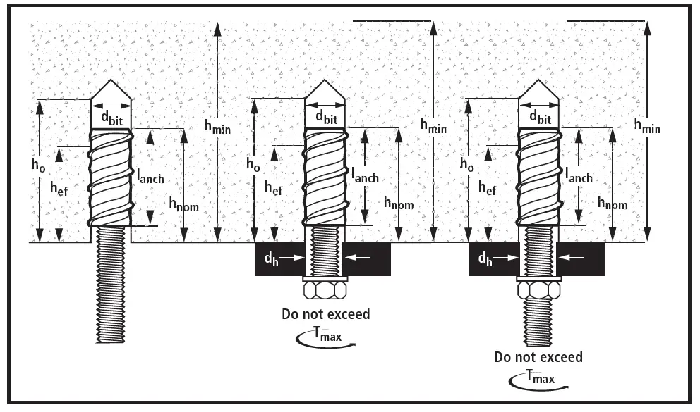
Dimensional Sketch for Snake+ Screw Anchor Installed with Steel Insert Element
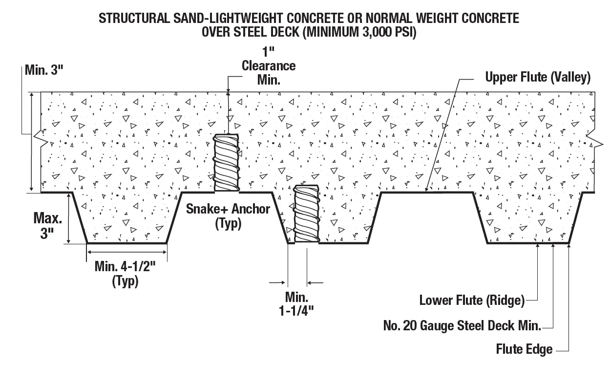
Installation Detail for Snake+ in the Topside of Concrete-Filled Steel Deck floor and Roof Assemblies1
3/8-inch diameter anchors may be placed in the topside of steel deck profiles provided the minimum topping thickness, minimum spacing distance and minimum edge distance are satisfied as given in the installation information table.
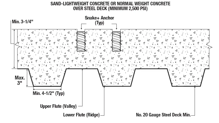
Installation Detail for Snake+ Installed in the Soffit of Concrete over Steel Deck floor and Roof Assemblies1
Anchors may be placed in the upper flute or lower flute of the steel deck profiles provided in minimum hole clearance is satisfied. Anchors in the lower flute may be installed with a maximum 1-inch offset in either direction from the center of the flute. The offset distance may be increased proportionally for profiles with lower flute widths greater
than those shown provided the minimum lower flute edge distance is also satisfied.
STRENGTH DESIGN INFORMATION
Tension Design Information for Snake+ Anchors1,2
| Design Characteristic | Notation | Units | Nominal Anchor Diameter | ||
| 3/8 inch | 1/2 inch | ||||
| Anchor category | 1,2 or 3 | – | 1 | 1 | |
| Nominal embedment depth | hnom | in. (mm) | 1-5/8 (41) | 2-3/16 (55) | |
| STEEL STRENGTH IN TENSION4 | |||||
| Minimum specified yield strength of steel insert element | fy | ksi (N/mm2) | AsTM A36 | 36.0 (248) | |
| AsTM A193, Grade B7 | 105.0 (724) | – | |||
| Minimum specified ultimate strength of steel insert element | futa | ksi (N/mm2) | AsTM A36 | 58.0 (400) | |
| AsTM A193, Grade B7 | 125.0 (862) | – | |||
| Effective tensile stress area of steel insert element | Ase, n | in2 (mm2) | 0.0775 (50) | 0.1419 (92) | |
| steel strength in tension | Nsa | lb (kN) | AsTM A36 | 4.495 (20.0) | 8,230 (37.0) |
| AsTM A193, Grade B7 | 9,685 (43.1) | – | |||
| reduction factor for steel strength3 | f | – | 0.65 | ||
| CONCRETE BREAKOUT STRENGTH IN TENSION8 | |||||
| Effective embedment | hef | in. (mm) | 1.10 (28) | 1.54 (39) | |
| Effectiveness factor for uncracked concrete | kucr | – | 24 | 30 | |
| Effectiveness factor for cracked concrete | kcr | – | 17 | 24 | |
| Modification factor for cracked and uncracked concrete5 | yc,n | – | 1.0 | ||
| Critical edge distance (uncracked concrete) | cac | in. (mm) | 3 (76) | 4 (102) | |
| Critical edge distance, topside of concrete-filled steel decks with minimum topping thickness10 | cac,deck,top | in. (mm) | 3 (76) | – | |
| reduction factor for concrete breakout strength3 | f | – | Condition B = 0.65 | ||
| PULLOUT STRENGTH IN TENSION8 | |||||
| Characteristic pullout strength, uncracked concrete (2,500 psi)6 | Np,uncr | lb (kN) | see note 7 | see note 7 | |
| Characteristic pullout strength, cracked concrete (2,500 psi)6 | Np,cr | lb (kN) | see note 7 | 1,665 (7.4) | |
| reduction factor for pullout strength3 | f | – | 0.65 (Condition B) | ||
| PULLOUT STRENGTH IN TENSION FOR SEISMIC APPLICATIONS8 | |||||
| Characteristic pullout strength, seismic (2,500 psi)6 | Np,eq | lb (kN) | see note 7 | 1,665 (7.4) | |
| reduction factor for pullout strength3 | f | – | Condition B = 0.65 | ||
| PULLOUT STRENGTH IN TENSION FOR SOFFIT OF SAND-LIGHT WEIGHT AND NORMAL-WEIGHT CONCRETE OVER STEEL DECK | |||||
| Characteristic pullout strength, uncracked concrete over steel deck6,9 | Np,deck,uncr | lb (kN) | 1,515 (6.7) | 1,625 (7.2) | |
| Characteristic pullout strength, cracked concrete over steel deck6,9 | Np,deck,cr | lb (kN) | 1,075 (4.8) | 1,300 (5.8) | |
| Characteristic pullout strength, cracked concrete over steel deck, seismic6,9 | Np,deck,eq | lb (kN) | 1,075 (4.8) | 1,300 (5.8) | |
| reduction factor for pullout strength, concrete over steel deck3 | f | – | Condition B = 0.65 | ||
| For sI: 1 inch = 25.4 mm, 1 ksi = 6.894 N/mm2; 1 lbf = 0.0044 kN. 1. The data in this table is intended to be used with the design provisions of ACI 318 (-19 and -14) Chapter 17 or ACI 318-11 Appendix D, as applicable; for anchors resisting seismic load combinations the additional requirements of ACI 318-19 17.10, ACI 318-14 17.2.3 or ACI 318-11 D.3.3, as applicable, must apply. 2. Installation must comply with published instructions and details. 3. All values of f were determined from the load combinations of IBC section 1605.2, ACI 318 (-19 and -14) section 5.3 or ACI 318-11 section 9.2. If the load combinations ACI 318-11 Appendix C are used, the appropriate value of f must be determined in accordance with ACI 318-11 D.4.4. For reinforcement that meets ACI 318 (-19 and -14) Chapter 17 or ACI 318-11 Appendix D, as applicable, requirements for Condition A, see ACI 318-19 17.5.3, ACI 318-14 17.3.3(c) or ACI 318-11 D.4.3(c), as applicable, for the appropriate f factor. 4. It is assumed that the threaded rod or bolt used with the snake+ anchor is a ductile steel element with minimum specified properties as listed in the table or an equivalent steel element. The snake+ anchor is considered a brittle steel element in tension as defined by AACI 318 (-19 and -14) 2.3 or ACI 318-11 D.1, as applicable. Tabulated values for steel strength in tension must be used for design. 5. For all design cases use yc,n = 1.0. The appropriate effectiveness factor for cracked concrete (kcr) and uncracked concrete (kuncr) must be used. 6. For all design cases use yc,p = 1.0. For concrete compressive strength greater than 2,500 psi, Npn = (pullout strength from table)*(specified concrete compressive strength/2,500)0.5. For concrete over steel deck the value of 2,500 must be replaced with the value of 3,000. 7. Pullout strength does not control design of indicated anchors. Do not calculate pullout strength for indicated anchor size and embedment. 8. Anchors are permitted to be used in lightweight concrete provided the modification factor la equal to 0.8l is applied to all values of Ö f’c affecting Nn and Vn. l shall be determined in accordance with the corresponding version of ACI 318. For anchors installed in the soffit of sand-lightweight concrete-filled steel deck and floor and roof assemblies, further reduction of the pullout values provided in not required. 9. Values for Np,deck are for sand-lightweight concrete (f’c,min = 3,000 psi) and additional lightweight concrete reduction factors need not be applied. In addition, evaluation for the concrete breakout capacity in accordance with ACI 318-19 17.6.2, ACI 318-14 17.4.2 or ACI 318-11 D.5.2, as applicable, is not required for anchors installed in the deck soffit (flute). 10. Anchors are permitted in the topside of concrete-filled steel deck assemblies in accordance with the Installation Detail for Anchors in the Top of Concrete over steel Deck Floor and roof Assemblies with Minimum Topping Thickness.. | |||||
Shear Design Information for Snake+ Anchors1,2
| Design Characteristic | Notation | Units | Nominal Anchor Diameter | ||
| 3/8 inch | 1/2 inch | ||||
| Anchor category | 1,2 or 3 | – | 1 | 1 | |
| Nominal embedment depth | hnom | in. (mm) | 1-5/8 (41) | 2-3/16 (55) | |
| STEEL STRENGTH IN SHEAR4 | |||||
| steel strength in shear5 | Vsa | lb (kN) | AsTM A36 | 770 (3.4) | 1,995 (8.9) |
| AsTM A193, Grade B7 | 1,655 (7.4) | – | |||
| reduction factor for steel strength3 | f | – | 0.60 | ||
| STEEL STRENGTH IN SHEAR FOR SEISMIC APPLICATIONS | |||||
| steel strength in shear, seismic7 | Vsa,eq | lb (kN) | AsTM A36 | 770 (3.4) | 1,995 (8.9) |
| AsTM A193, Grade B7 | 1,655 (7.4) | – | |||
| reduction factor for steel strength3 | f | – | Condition B = 0.60 | ||
| CONCRETE BREAKOUT STRENGTH IN SHEAR6 | |||||
| Nominal outside anchor diameter | da | in. (mm) | 0.500 (12.7) | 0.750 (19.1) | |
| Load bearing length of anchor | ℓe | – | 1.10 (28) | 1.54 (39) | |
| reduction factor for concrete breakout strength3 | f | – | Condition B = 0.70 | ||
| PRYOUT STRENGTH IN SHEAR6 | |||||
| Coefficient for pryout strength | kcp | – | 1.0 | 1.0 | |
| Effective embedment | hef | in. (mm) | 1.10 (28) | 1.54 (39) | |
| reduction factor for pryout strength3 | f | – | Condition B = 0.70 | ||
| STEEL STRENGTH IN SHEAR FOR SOFFIT OF SAND-LIGHT WEIGHT AND NORMAL-WEIGHT CONCRETE OVER STEEL DECK9 | |||||
| steel strength in shear, concrete over steel deck8 | Vsa,deck | lb (kN) | AsTM A36 | 770 (3.4) | 1,995 (8.9) |
| AsTM A193, Grade B7 | 1,655 (7.4) | – | |||
| steel strength in shear, concrete over steel deck, seismic8 | Vsa,deck,eq | lb (kN) | AsTM A36 | 770 (3) | 1,995 (8.9) |
| AsTM A193, Grade B7 | 1,665 (7.4) | – | |||
| reduction factor for steel strength, seismic3 | f | – | Condition B = 0.60 | ||
| For sI: 1 inch = 25.4 mm, 1 lbf = 0.0044 kN. 1. The data in this table is intended to be used with the design provisions of ACI 318-14 Chapter 17 or ACI 318-11 Appendix D, as applicable; for anchors resisting seismic load combinations the additional requirements of ACI 318-19 17.10, ACI 318-14 17.2.3 or ACI 318-11 D.3.3 shall apply. 2. Installation must comply with published instructions and details. 3. All values of f were determined from the load combinations of IBC section 1605.2, ACI 318 (-19 and -14) section 5.3, or ACI 318-11 section 9.2, as applicable. If the load combinations of ACI 318-11 Appendix C are used, the appropriate value of f must be determined in accordance with ACI 318-11 D.4.4. For reinforcement that meets ACI 318 (-19 and -14) Chapter 17 or ACI 318-11 Appendix D, as applicable, requirements for Condition A, see ACI 318-19 17.5.3, ACI 318-14 17.3.3(c) or ACI 318-11 D.4.3(c), as applicable, for the appropriate f factor. 4. It is assumed that the threaded rod or bolt used with the snake+ anchor will be a ductile steel element as defined by ACI 318 (-19 and -14) 2.3 or ACI 318-11 D.1, as applicable. 5. Tabulated values for steel strength in shear must be used for design. These tabulated values are lower than calculated results using equation 17.7.1.2b in ACI 318-19 17.5.1.2b in ACI 318- 14, D-29 in ACI 318-11, and ACI 318-14 17.5.1.2 or ACI 318-11 D.6.1.2, as applicable. 6. Anchors are permitted to be used in lightweight concrete provided the modification factor la equal to 0.8l is applied to all values of Ö f’c affecting Nn and Vn. l shall be determined in accordance with the corresponding version of ACI 318. For anchors installed in the soffit of sand-lightweight concrete-filled steel deck and floor and roof assemblies, further reduction of the pullout values provided in not required. 7. Tabulated values for steel strength in shear are for seismic applications and based on test results in accordance with ACI 355.2 section 9.6. 8. Tabulated values for Vsa,deck are for sand-lightweight concrete (f’c,min = 3,000 psi) and additional lightweight concrete reduction factors need not be applied. In addition, evaluation for the concrete breakout capacity in accordance with ACI 318-19 17.7.2, ACI 318-14 17.5.2 or ACI 318-11 D.6.2, as applicable, and the pryout capacity in accordance with ACI 318-19 17.7.3, ACI 318-14 17.5.3 or ACI 318-11 D.6.3 are not required for anchors installed in the deck soffit (flute). 9. shear loads for anchors installed through steel deck into concrete may be applied in any direction. | |||||
Tension and Shear Design Strengths for Snake+ Anchors Installed in Cracked Concrete1,2,3,4,5,6,7
| Nominal Anchor Size (in.) | Nominal Embed. hnom (in. ) | Steel Insert Element (Threaded Rod or Bolt) | Minimum Concrete Compressive Strength, f’c (psi) | |||||||||
| 2,500 | 3,000 | 4,000 | 6,000 | 8,000 | ||||||||
| fNn Tension (lbs.) | fVn Shear (lbs.) | fNn Tension (lbs.) | fVn Shear (lbs.) | fNn Tension (lbs.) | fVn Shear (lbs.) | fNn Tension (lbs.) | fVn Shear (lbs.) | fNn Tension (lbs.) | fVn Shear (lbs.) | |||
| 3/8 | 1-5/8 | AsTM A36 | 635 | 500 | 700 | 500 | 805 | 500 | 985 | 500 | 1,140 | 500 |
| AsTM A193 Grade B7 | 635 | 685 | 700 | 750 | 805 | 870 | 985 | 1,065 | 1,140 | 1,075 | ||
| 1/2 | 2-3/16 | AsTM A36 | 1,080 | 1,295 | 1,185 | 1,295 | 1,370 | 1,295 | 1,675 | 1,295 | 1,935 | 1,295 |
| ■ – Anchor Pullout/Pryout strength Controls ■ – Concrete Breakout strength Controls ■ – steel strength Controls | ||||||||||||
Tension and Shear Design Strengths for Snake+ Anchors Installed in Uncracked Concrete1,2,3,4,5,6
| Nominal Anchor Size (in.) | Nominal Embed. hnom (in. ) | Steel Insert Element (Threaded Rod or Bolt) | Minimum Concrete Compressive Strength, f’c (psi) | |||||||||
| 2,500 | 3,000 | 4,000 | 6,000 | 8,000 | ||||||||
| fNn Tension (lbs.) | fVn Shear (lbs.) | fNn Tension (lbs.) | fVn Shear (lbs.) | fNn Tension (lbs.) | fVn Shear (lbs.) | fNn Tension (lbs.) | fVn Shear (lbs.) | fNn Tension (lbs.) | fVn Shear (lbs.) | |||
| 3/8 | 1-5/8 | AsTM A36 | 900 | 500 | 985 | 500 | 1,140 | 500 | 1,395 | 500 | 1,610 | 500 |
| AsTM A193 Grade B7 | 900 | 970 | 985 | 1,060 | 1,140 | 1,075 | 1,395 | 1,075 | 1,610 | 1,075 | ||
| 1/2 | 2-3/16 | AsTM A36 | 1,865 | 1,295 | 2,040 | 1,295 | 2,355 | 1,295 | 2,885 | 1,295 | 3,335 | 1,295 |
| ■ – Anchor Pullout/Pryout strength Controls ■ – Concrete Breakout strength Controls ■ – steel strength Controls | ||||||||||||
- Tabular values are provided for illustration and are applicable for single anchors installed in normal-weight concrete with minimum slab thickness, ha = hmin, and with
the following conditions:- ca1 is greater than or equal to the critical edge distance, cac (table values based on ca1 = cac).
- ca2 is greater than or equal to 1.5 times ca1.
- Calculations were performed according to ACI 318-19 Chapter 17. The load level corresponding to the controlling failure mode is listed. (e.g. For tension: steel, concrete breakout and pullout; For shear: steel, concrete breakout and pryout). Furthermore, the capacities for concrete breakout strength in tension and pryout strength in shear are calculated using the effective embedment values, hef, for the selected anchors as noted in the design information tables. Please also reference the installation specifications for more information.
- Strength reduction factors (ø) were based on ACI 318-19 Section 5.3 for load combinations.
Condition B is assumed. - Tabular values are permitted for static loads only, seismic loading is not considered with these tables.
- For designs that include combined tension and shear, the interaction of tension and shear loads must be calculated in accordance with ACI 318-19 Chapter 17.
- Interpolation is not permitted to be used with the tabular values. For intermediate base material compressive strengths please see ACI 318-19 Chapter 17. For other
design conditions including seismic considerations please see ACI 318-19 Chapter 17. - For seismic design in accordance with ACI 318, the tabulated tension design strengths for concrete breakout and pullout must be multiplied by a factor of 0.75.
REDUNDANT FASTENING
Redundant Fastening Applications
For an anchoring system designed with redundancy, the load maintained by an anchor that experiences failure or excessive deflection can be transmitted to neighboring anchors without significant consequences to the fixture or remaining resistance of the anchoring system. In addition to the requirements for anchors, the fixture being attached shall be able to resist the forces acting on it assuming one of the fixing points is not carrying load. It is assumed that by adhering to the limits placed on n1, n2 and n3 below, redundancy will be satisfied.
Anchors qualified for redundant applications may be designed for use in normal weight and sand-lightweight cracked and uncracked concrete. Concrete compressive strength of 2,500 psi shall be used for design. No increase in anchor capacity is permitted for concrete compressive strengths greater than 2,500 psi. The anchor installation is limited to concrete with a compressive strength of 8,500 psi or less.
Redundant applications shall be limited to structures assigned to Seismic Design Categories A or B only.
Redundant applications shall be limited to support of nonstructural elements.
Strength Design (Redundant Fastening):
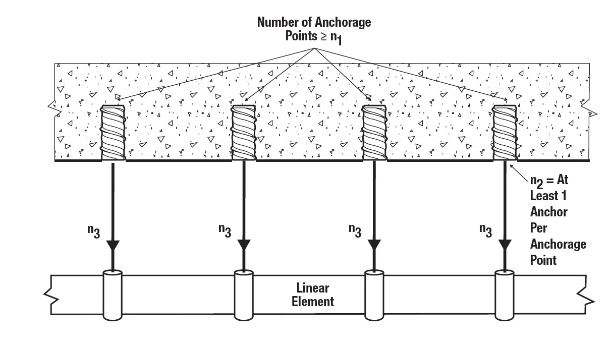
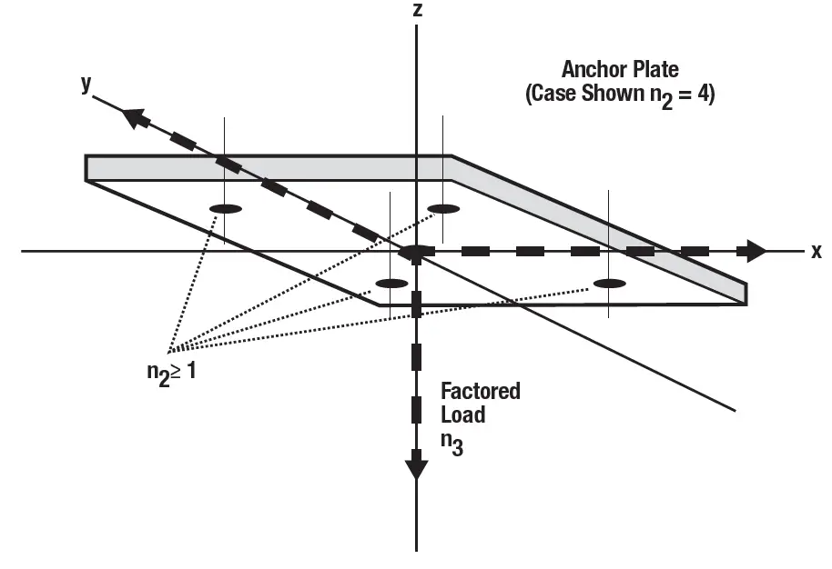
For strength design, a redundant system is achieved by specifying and limiting the following variables
n1 = the total number of anchorage points supporting the linear element
n2 = number of anchors per anchorage point
n3 = factored load at each anchorage point, lbs., using load combinations from IBC Section 1605.2.1 or ACI 318 (-19 and -14) Section 5.3 or ACI 318-11 Section 9.2.
Strength Design (SD)
Design values for use with strength design shall be established taking fra • Fra. See redundant fastening design information table for Snake+ design resistance.
Allowable Stress Design (Redundant Fastening):
Design values for use with allowable stress design shall be established taking
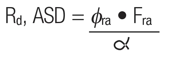
Where å is the conversion factor calculated as the weighted average of the load factors from the controlling load combination. For example, the conversion factor, å is equal to 1.4 assuming all dead load.
Installation Information for Snake+ Screw Anchor in Redundant Fastening Applications
| Anchor Property/ Setting Information | Notation | Units | Nominal Anchor Size / Threaded Couplier Diameter (inch) | ||
| 1/4 | 3/8 | 1/2 | |||
| Nominal drill bit diameter (ANsI) | dbit | in. | 3/8 | 1/2 | 3/4 |
| Nominal embedment depth | hnom | in. (mm) | 1-5/8 (41) | 1-5/8 (41) | 2-3/16 (55) |
| Effective embedment | hef | in. (mm) | 1.10 (28) | 1.10 (28) | 1.54 (39) |
| Minimum hole depth | ho | in. (mm) | 2 (51) | 2 (51) | 2-1/2 (64) |
| Minimum concrete member thickness | hmin | in. (mm) | 3 (76.2) | 3 (76.2) | 3 (76.2) |
| overall anchor legnth | ℓanch | in. (mm) | 1-1/4 (32) | 1-1/4 (32) | 1-11/16 (43) |
| Minimum edge distance, redundant fastening1 | cmin = cac | in. (mm) | 4 (102) | 4 (102) | 4 (102) |
| Minimum spacing distance, redundant fastening1 | smin | in. (mm) | 8 (203) | 8 (203) | 8 (203) |
| Max impact wrench power (torque) | Tscrew | ft.-lb. (N-m) | 120 (163) | 345 (468) | 345 (468) |
| Max tightening torque of steel insert element (threaded rod or bolt) | Tmax | ft.-lb. (N-m) | 4 (6) | 8 (11) | 36 (49) |
| Approximate internal thread depth | – | in. (mm) | 11/32 | 23/32 | 15/16 |
| 1. Tabulated minimum spacing and edge distances are applicable only for redundant fastening applications. | |||||
Redundant Fastening Design Information for Snake+ Anchors1,2,3
| Anchor Property/ Setting Information | Notation | Units | Nominal Anchor Size | |||||
| 1/4″ | 3/8″ | 1/2″ | ||||||
| Anchor category | 1,2 or 3 | – | 1 | 1 | 1 | |||
| Nominal embedment depth | hnom | in. (mm) | 1-5/8 (41) | 1-5/8 (41) | 2-3/16 (55) | |||
| CHARACTERISTIC STRENGTH (RESISTANCE) INSTALLED IN CONCRETE4,5 | ||||||||
| resistance, cracked or uncracked concrete (2,500psi) |
Fra | lb (kN) | Number of anchorage points | Number of anchorage points | Number of anchorage points | |||
| n1 ≥ 4 | n1 ≥ 3 | n1 ≥ 4 | n1 ≥ 3 | n1 ≥ 4 | n1 ≥ 3 | |||
| 550 (2.5) | 360 (1.6) | 675 (3.0) | 450 (2.0) | 675 (3.0) | 450 (2.0) | |||
| strength reduction factor3 | fra | – | 0.65 | |||||
| CHARACTERISTIC STRENGTH (RESISTANCE) FOR SAND-LIGHTWEIGHT AND NORMAL WEIGHT CONCRETE OVER STEEL DECK4,6 | ||||||||
| resistance, cracked or uncracked concrete over steel deck (2,500 psi) |
Fra,deck | lb (kN) | Number of anchorage points | Number of anchorage points | Number of anchorage points | |||
| n1 ≥ 4 | n1 ≥ 3 | n1 ≥ 4 | n1 ≥ 3 | n1 ≥ 4 | n1 ≥ 3 | |||
| 550 (2.5) | 360 (1.6) | 675 (3.0) | 450 (2.0) | 675 (3.0) | 450 (2.0) | |||
| strength reduction factor3 | fra | – | 0.65 | |||||
| For sI: 1 inch = 25.4 mm, 1 lbf = 0.0044 kN. 1. The data in this table is intended to be used with the design provisions of section 4.3 of this report; loads may be applied in tension, shear or any combination thereof. 2. Installation must comply with published instructions and this report. 3. All values of f were determined from the load combinations of IBC section 1605.2, ACI 318 (-19 and -14) section 5.3 or ACI 318 (-11) section 9.2, as applicable. 4. It is assumed that the threaded rod or bolt used with the snake+ anchor has properties as listed in Tension Design Information table. 5. Anchors are permitted to be used in lightweight concrete provided the design strength fra Fra is multiplied by the modification factor la. The modification factor la is equal to 0.8l, l shall be determined in accordance with the corresponding version of ACI 318. For anchors installed in the soffit of sand-lightweight concrete-filled steel deck and floor and roof assemblies, further reduction of the pullout values provided in not required. 6. For installations through the soffit of steel deck into concrete see the installation detail. Anchors in the lower flute may be installed with a maximum 1-inch offset in either direction from center of the flute. In addition, anchors shall have an axial spacing along the flute equal to the greater of 3hef or 1.5 times the flute width. | ||||||||
PERFORMANCE DATA (ASD)
| Nominal Anchor Diameter in. | Minimum Embedment Depth in. (mm) | Minimum Concrete Compressive Strength | |||||||
| f’c = 2,500 psi (17.2 MPa) | f’c = 3,000 psi (20.7 MPa) | f’c = 4,000 psi (20.7 MPa) | f’c = 6,000 psi (41.4 MPa) | ||||||
| Tension lbs. (kN) | Shear lbs. (kN) | Tension lbs. (kN) | Shear lbs. (kN) | Tension lbs. (kN) | Shear lbs. (kN) | Tension lbs. (kN) | Shear lbs. (kN) | ||
| 1/4 | 1-5/8 (41) | 2,130 (9.5) | 1,045 (4.6) | 2,335 (10.4) | 1,045 (4.6) | 2,335 (10.4) | 1,045 (4.6) | – | – |
| 3/8 | 1-5/8 (41) | 2,165 (9.7) | 1,045 (4.6) | 2,370 (10.6) | 1,045 (4.6) | 2,735 (10.6) | 1,045 (4.6) | 3,190 (14.2) | 1,045 (4.6) |
| 1/2 | 2-3/16 (55) | 5,590 (24.9) | 2,050 (9.1) | 6,125 (27.3) | 2,050 (9.1) | 7,075 (27.3) | 2,050 (9.1) | 7,240 (32.0) | 2,050 (9.1) |
| 1. Tabulated load values are for anchors installed in uncracked concrete. Concrete compressive strength must be at the specified minimum at the time of installation. 2. Ultimate load capacities must be reduced by a minimum safety factor of 4.0 or greater to determine allowable working load. 3. The tabulated load values are applicable to single anchors in uncracked concrete installed at critical spacing distance between anchors and at critical edge distance. 4. Ultimate shear capacity is controlled by steel strength of AsTM A36 element (or equivalent). | |||||||||
ORDERING INFORMATION
Carbon Steel Snake+ Screw Anchor
| Cat. No. | Nominal Anchor Size | Internal Thread Size (UNC) | Anchor Outside Diameter | Std. Pack | Std. Ctn. |
| 6400sD-PWr | 1/4″ | 1/4″-20 | 3/8″ | 100 | 1,000 |
| 6401sD-PWr | 3/8″ | 3/8″-16 | 1/2″ | 50 | 500 |
| 6403sD-PWr | 1/2″ | 1/2″-13 | 3/4″ | 50 | 300 |
| 1. Each box comes with one setting tool. | |||||
Setting Tool for Snake+ Screw Anchor
| Cat. No. | Nominal Anchor Size | Std. Pack |
| 6402sD-PWr | 1/4″ | 1 |
| 6407sD-PWr | 3/8″ | 1 |
| 6404sD-PWr | 1/2″ | 1 |
| Anchor Setting Information | Nominal Anchor Diameter (Inch) | |||||
| 1/4″ | 3/8″ | 1/2″ | ||||
| Max Impact Wrench Power | 120 ft-lbs | 345 ft-lbs | 345 ft-lbs | |||
| Suggested 20V Max Impact Wrench, Tool Setting / Speed and Cat. No. | Full speed | speed 1 | speed 1 | speed 2 | speed 1 | speed 2 |
| DCF902 | DCF921, DCF922, DCF923, DCF891, DCF892, DCF900 | DCF911, DCF913, DCF900 | DCF921, DCF922, DCF923, DCF891, DCF892 | DCF911, DCF913, DCF900 | DCF921, DCF922, DCF923, DCF891, DCF892 | |
| Cat. No. | DCF901 | DCF903 | DCF911 | DCF913 | DCF921 | DCF922 | DCF923 | DCF891 | DCF892 |
| Anvil size | 3/8″ | 1/2″ | 3/8″ | 1/2″ | 1/2″ | 3/8″ | 1/2″ | 1/2″ | 1/2″ |
| Anvil Type | Hog ring | Hog ring | Hog ring | Hog ring | Hog ring | Detent | Hog ring | Hog ring | Detent |
| MAX Fastening Torque | speed 1: 250 ft-lbs | speed 1: 250 ft-lbs | speed 1: 250 ft-lbs | speed 1: 250 ft-lbs | speed 1: 100 ft-lbs speed 2: 300 ft-lbs | speed 1: 100 ft-lbs speed 2: 300 ft-lbs | speed 1: 100 ft-lbs speed 2: 300 ft-lbs | speed 1: 100 ft-lbs. speed 2: 300 ft-lbs. speed 3: 600 ft-lbs | speed 1: 100 ft-lbs. speed 2: 300 ft-lbs. speed 3: 600 ft-lbs |


