DEWALT MINI-UNDERCUT Plus Internally Threaded Undercut Anchor
PRODUCT DESCRIPTION
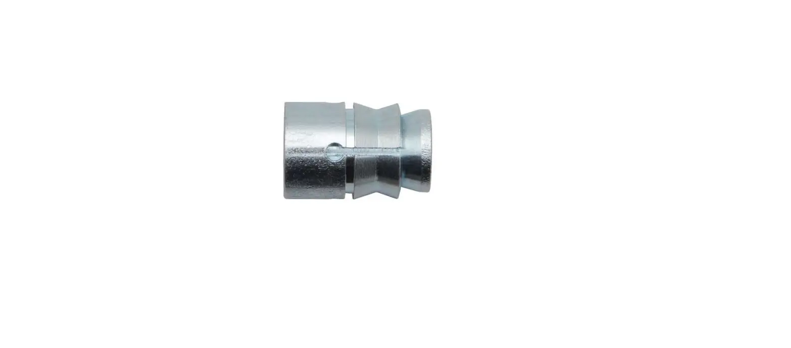
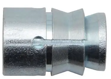
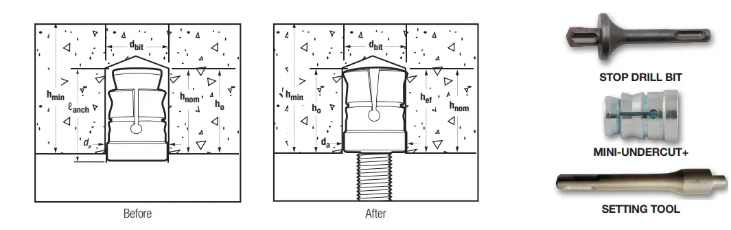
The Mini-Undercut+ anchor is an internally threaded, self-undercutting anchor designed for performance in cracked and uncracked concrete. Suitable base materials include post-tension concrete (PT slabs), hollow-core precast concrete, normal-weight concrete, and lightweight concrete. The Mini-Undercut+ anchor is installed into a pre-drilled hole with a power tool and a setting tool. After installation, a steel element is threaded into the anchor body. The result is an anchor which can provide consistent behavior at shallow embedments as low as 3/4 of an inch.
GENERAL APPLICATIONS AND USES
- Tension zone / cracked concrete
- Suspended Conduit
- Pipe supports
- Cable Trays and Strut
- Suspended Lighting
- Seismic attachments (SDC A – F)
FEATURE AND BENEFITS
- Ideal for precast hollow-core plank and post-tensioned concrete slabs
- Cracked concrete tested alternative to a mini dropin anchor
- ANSI carbide stop bit with an enlarged shoulder for accurate drill depth
- Anchor design allows for shallow embedment as low as 3/4 of an inch
- Internally threaded anchor for easy adjustment and removability of threaded rod or bolt+ Drill and drive the anchor with one tool for fast anchor installation
APPROVALS AND LISTINGS
- International Code Council, Evaluation Service (ICC-ES), ESR-3912 for Concrete and Hollow-Core precast slabs, code compliant with the International Building Code/International Residential Code: 2021 IBC/IRC, 2018 IBC/IRC, 2015 IBC/IRC and 2012 IBC/IRC
- Tested in accordance with ACI 355.2 (including ASTM E488) and ICC-ES AC193 for use in cracked and uncracked concrete under the design provisions of ACI 318 (-19 or -14) Chapter 17 or ACI 318-11 Appendix D
- Evaluated and qualified by an accredited independent testing laboratory for recognition in cracked and uncracked concrete including seismic and wind loading (anchor Category 1)
GUIDE SPECIFICATIONS
CSI Divisions: 03 16 00 – Concrete Anchoring and 05 05 19 – Post Installed Concrete Anchors. Anchors shall be Mini-Undercut+ as supplied by DEWALT, Towson, MD. Anchors shall be installed in accordance with published instructions and the Authority Having Jurisdiction.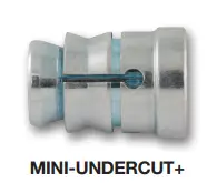
THREAD VERSION
- UNC Thread
ANCHOR MATERIALS
- Zinc-plated carbon steel
ANCHOR SIZE RANGE (TYP.)
- 3/8″ diameter (UNC)
SUITABLE BASE MATERIALS
- Post-Tension Concrete
- Precast Hollow-Core Plank
- Normal-weight concrete
- Lightweight concrete
INSTALLATION INSTRUCTIONS
Installation Procedure (using SDS plus System)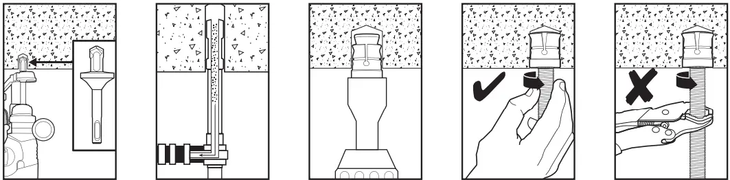
- Using the required stop drill bit, drill a hole into the base material to the required depth using the shoulder of the drill bit as a guide. The tolerances of the drill bit used must meet the requirements of ANSI Standard B212.15.
- Remove dust and debris from the hole during drilling (e.g. dust extractor) or following drilling (e.g. suction-forced air) to extract loose particles created by drilling.
- Attach the required SDS setting tool to the hammer drill. Mount the open end of the anchor onto the setting tool. Drive the anchor into the hole until the shoulder of the anchor is flush with the base material.
- Thread the rod or bolt by hand until snug and tight (minimum of 4 full rotations).
- Do not further tighten with an adjustable wrench or similar tool.
Installation Specifications for Mini-Undercut+ Anchor and Supplemental Information1,2,3
| Anchor Property/Setting Information | Symbol | Units | Nominal Anchor Diameter (inch) | |
| 3/8 | ||||
| Anchor outside diameter | da | in. (mm) | 0.625 (15.9) | |
| Internal thread diameter (UNC) | d | in. (mm) | 3/8 (9.5) | |
| Nominal drill bit diameter (ANSI) | debit | in. | 5/8 | |
| Minimum nominal embedment depth | Phnom | in. (mm) | 3/4 (19) | |
| Effective embedment depth | hef | |||
| Hole depth | ho | |||
| overall anchor length (before setting) | ℓanch | in. (mm) | 15/16 (24) | |
| Approximate tool impact power (hammer-drill) | – | J | 2.1 to 3.0 | |
| Minimum diameter of hole clearance in the fixture for steel insert element (following anchor installation) | DH | in. | 7/16 | |
| Minimum member thickness in concrete | human | in. (mm) | 2-1/2 (64) | |
| Minimum cover thickness in hollow core concrete slabs (see Hollow-Core concrete figure) | hm, core | in. (mm) | 1-1/2 (38) | |
| Minimum edge distance | cmin | in. (mm) | 2-1/2 (64) | |
| Minimum spacing distance | smin | in. (mm) | 3 (76) | |
| Maximum installation torque | Tmax | ft.-lb. (N-m) | 5 (7) | |
| Effective tensile stress area (undercut anchor body) | Ase | in.2 (mm2) | 0.044 (28.4) | |
| Minimum specified ultimate strength | futa | psi | 95,000 | |
| Minimum specified yield strength | fya | psi | 76,000 | |
| Mean axial stiffness4 | Uncracked concrete | bunch | lbf/in. | 50,400 |
| Cracked concrete | bcr | lbf/in. | 29,120 | |
| For sI: 1 inch = 25.4 mm, 1 ft-lbf = 1.356 N-m. 1. The information presented in this table is to be used in conjunction with the design criteria of ACI 318 (-19 and -14) Chapter 17 or ACI 318-11 Appendix D, as applicable. 2. For installation detail for anchors in hollow-core concrete slabs, see the Hollow-Core concrete figure. 3. The embedment depth, Phnom, is measured from the outside surface of the concrete member to the embedded end of the anchor. 4. Mean values are shown, actual stiffness varies considerably depending on concrete strength, loading, and geometry of application. | ||||
Mini-Undercut+ Anchor Detail
Mini-Undercut+ Anchor Installed with Steel Insert Element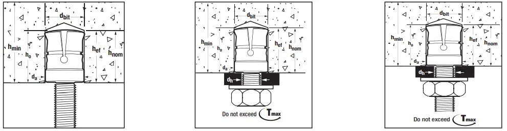
REFERENCE DATA (ASD)
Ultimate and Allowable Tension Load Capacities for Mini-Undercut+ in Normal-Weight Concrete1,2,3,4
| Nominal Rod/ Anchor Diameter d in. | Minimum Nominal Embed. Depth in. (mm) | Minimum Concrete Compressive Strength | |||||||
| f’c = 3,000 psi (20.7 MPa) | f’c = 4,000 psi (27.6 MPa) | ||||||||
| Ultimate | Allowable | Ultimate | Allowable | ||||||
| Tension lbs (kN) | Shear lbs (kN) | Tension lbs (kN) | Shear lbs (kN) | Tension lbs (kN) | Shear lbs (kN) | Tension lbs (kN) | Shear lbs (kN) | ||
| 3/8 | 3/4 (19) | 1,535 (6.8) | 1,975 (8.8) | 385 (1.7) | 495 (2.2) | 1,770 (7.9) | 2,275 (10.1) | 445 (2.0) | 570 (2.5) |
| 1. Tabulated load values are for anchors installed in uncracked concrete. Concrete compressive strength must be at the specified minimum at the time of installation. 2. Allowable load capacities are calculated using an applied safety factor of 4.0. 3. Linear interpolation may be used to determine allowable loads for intermediate compressive strengths. 4. For lightweight concrete, tabulated values must be multiplied by 0.60. | |||||||||
Ultimate and Allowable Tension Load Capacities for Mini-Undercut+ in Hollow-Core Plank1,2,3
| Nominal Rod/ Anchor Diameter d in. | Minimum Nominal Embed. Depth in. (mm) | Minimum Concrete Compressive Strength | |||||||||||
| f’c = 5,000 psi (34.5 MPa) | f’c = 6,000 psi (41.4 MPa) | f’c = 8,000 psi (55.2 MPa) | |||||||||||
| Ultimate | Allowable | Ultimate | Allowable | Ultimate | Allowable | ||||||||
| Tension lbs (kN) | Shear lbs (kN) | Tension lbs (kN) | Shear lbs (kN) | Tension lbs (kN) | Shear lbs (kN) | Tension lbs (kN) | Shear lbs (kN) | Tension lbs (kN) | Shear lbs (kN) | Tension lbs (kN) | Shear lbs (kN) | ||
| 3/8 | 3/4 (19) | 1,855 (8.3) | 2,590 (11.5) | 465 (2.1) | 650 (2.9) | 2,035 (9.1) | 2,835 (12.6) | 510 (2.3) | 710 (3.2) | 2,345 (10.4) | 3,275 (14.6) | 585 (2.6) | 820 (3.6) |
| 1. Tabulated load values are for anchors installed in uncracked concrete. Concrete compressive strength must be at the specified minimum at the time of installation. 2. Allowable load capacities are calculated using an applied safety factor of 4.0. 3. Linear interpolation may be used to determine allowable loads for intermediate compressive strengths. | |||||||||||||
Installation Detail: Mini-Undercut+ in the Underside of Hollow-Core Concrete Slabs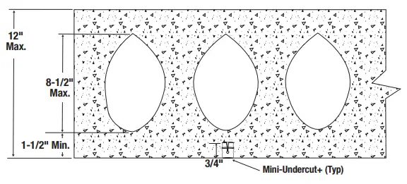
DESIGN INFORMATION
Tension Design Information for Mini-Undercut+ Anchors in the Underside of Concrete and the Underside of Hollow-Core Concrete Slabs1,2,3,4,5,6,7,8,9
| Design Characteristic | Notation | Units | Nominal Anchor Size / Threaded Rod Diameter (inch) |
| 3/8 | |||
| Anchor category | 1, 2 or 3 | – | 1 |
| Nominal embedment depth | hnom | in. (mm) | 3/4 (19) |
| Steel Strength In Tension (ACI 318-19 17.6.1, ACI 318-14 17.4.1 or ACI 318-11 D.5.1) | |||
| steel strength in tension | Nsa | lb (kN) | 4,180 (18.6) |
| reduction factor for steel strength | f | – | 0.65 |
| Concrete Breakout Strength In Tension (ACI 318-19 17.6.2, ACI 318-14 17.4.2 or ACI 318-11 D.5.2) | |||
| Effective embedment | hef | in. (mm) | 3/4 (19) |
| Effectiveness factor for uncracked concrete | kuncr | – | 24 |
| Effectiveness factor for cracked concrete | kcr | – | 17 |
| Modification factor for cracked and uncracked concrete | Yc,n | – | 1.0 (see note 5) |
| Critical edge distance (uncracked concrete only) | cac | in. (mm) | 2.5 (64) |
| reduction factor, concrete breakout strength3 | f | – | 0.40 |
| Pullout Strength In Tension (ACI 318-19 17.6.3, ACI 318-14 17.4.3 or ACI 318-11 D.5.3) | |||
| Pullout strength, uncracked concrete | Np,uncr | lb (kN) | see note 7 |
| Pullout strength, cracked concrete | Np,cr | lb (kN) | 455 (2.0) |
| reduction factor, pullout strength | f | – | 0.40 |
| Pullout Strength In Tension For Seismic Applications (ACI 318-19 17.10.3, ACI 318-14 17.2.3.3 or ACI 318-11 D.3.3.3)8 | |||
| Characteristic pullout strength, seismic | Np, eq | lb (kN) | 410 (1.82) |
| reduction factor, pullout strength, seismic | f | – | 0.40 |
| For sI: 1 inch = 25.4 mm, 1 ksi = 6.894 N/mm2; 1 lbf = 0.0044 kN. 1. The data in this table is intended to be used with the design provisions of ACI 318 (-19 and -14) Chapter 17 or ACI 318-11 Appendix D, as applicable; for anchors resisting seismic load combinations the additional requirements of ACI 318-19 17.10, ACI 318-14 17.2.3 or ACI 318-11 D.3.3, as applicable, shall apply. 2. Installation must comply with the manufacturer’s published installation instructions and details. 3. All values of f are applicable with the load combinations of 2021 IBC section 1605.1 or 2018, 2015 and 2012 IBC section 1605.2, ACI 318 (-19 or -14) section 5.3, or ACI 318-11 section 9.2. For concrete failure modes, no increase for ACI 318-19 17.5.3 supplementary reinforcement present, ACI 318-14 17.3.3 Condition A or ACI 318-11 D.4.3 Condition A is permitted. 4. The threaded rod or bolt strength must also be checked, and the controlling value of fish between the anchor and rod must be used for design. 5. select the appropriate effectiveness factor for cracked concrete (KCR) or uncracked concrete (lunch) and use yc,n = 1.0. 6. The characteristic pullout strength for concrete compressive strengths greater than 2,500 psi for anchors may be increased by multiplying the value in the table by (C / 2,500)0.5 for psi or (C / 17.2)0.5 for MPa. For hollow-core concrete slabs, the characteristic pullout strength for concrete compressive strengths greater than 6,000 psi for anchors may be increased by multiplying the value in the table by (C / 6,000)0.5 for psi or (C / 41.4)0.5 for MPa. 7. Pullout strength does not control the design of indicated anchors. Do not calculate pullout strength for the indicated anchor size and embedment. 8. reported values for characteristic pullout strength in tension for seismic applications are based on test results per ACI 355.2, section 9.5. 9. Anchors are permitted to be used in sand-lightweight concrete provided the modification factor la equal to 0.8l is applied to all values of Ö fact affecting Nn and Vn. l shall be determined in accordance with the corresponding version of ACI 318. | |||
Shear Design Information for Mini-Undercut+ Anchors in the Underside of Concrete and the Underside of Hollow-Core Concrete Slabs1,2,3,4,7
| Design Characteristic | Notation | Units | Nominal Anchor Size / Threaded Rod Diameter (inch) |
| 3/8 | |||
| Anchor category | 1, 2 or 3 | – | 1 |
| Nominal embedment depth | hnom | in. (mm) | 3/4 (19) |
| Steel Strength in Shear (ACI 318-19 17.7.1, ACI 318-14 17.5.1 or ACI 318-11 D.6.1)5 | |||
| steel strength in shear | Vsa | lb (kN) | 985 (4.4) |
| reduction factor, steel strength | f | – | 0.60 |
| Steel Strength in Shear for Seismic (ACI 318-19 17.10.3, ACI 318-14 17.2.3.3 or ACI 318-11 D.3.3.3)6 | |||
| steel strength in shear, seismic | Vsa, eq | lb (kN) | 895 (4.0) |
| reduction factor, steel strength in shear, seismic | f | – | 0.60 |
| Concrete Breakout Strength in Shear (ACI 318-19 17.7.2, ACI 318-14 17.5.2 or ACI 318-11 D.6.2) | |||
| Load bearing length of anchor in shear | ℓe | in. (mm) | 3/4 (19) |
| Nominal outside anchor diameter | da | in. (mm) | 0.625 (15.9) |
| reduction factor for concrete breakout strength | f | – | 0.45 |
| Pryout Strength in Shear (ACI 318-19 17.7.3, ACI 318-14 17.5.3 or ACI 318-11 D.6.3) | |||
| Coefficient for pryout strength | kcp | – | 1.0 |
| Effective embedment | hef | in. (mm) | 3/4 (19) |
| reduction factor, pryout strength | f | – | 0.45 |
| For sI: 1 inch = 25.4 mm, 1 lbf = 0.0044 kN. 1. The data in this table is intended to be used with the design provisions of ACI 318 (-19 and -14) Chapter 17 or ACI 318-11 Appendix D, as applicable; for anchors resisting seismic load combinations the additional requirements of ACI 318-19 17.10, ACI 318-17 17.2.3 or ACI 318-11 D.3.3, as applicable shall apply 2. Installation must comply with manufacturer’s published installation instructions and details. 3. All values of f are applicable with the load combinations of 2021 IBC section 1605.1 or 2018, 2015 and 2012 IBC section 1605.2, ACI 318 (-19 or -14) section 5.3, or ACI 318-11 section 9.2. For concrete failure modes, no increase for ACI 318-19 17.5.3 supplementary reinforcement present, ACI 318-14 17.3.3 Condition A or ACI 318-11 D.4.3 Condition A is permitted. 4. The strengths shown in the table are for the Mini-Undercut+ anchors only. Design professional is responsible for checking threaded rod strength in tension, shear, and combined tension and shear, as applicable. 5. reported values for steel strength in shear are based on test results per ACI 355.2, section 9.4 and must be used for design in lieu of the calculated results using equation 17.7.1.2b in ACI 318-19, 17.5.1.2b of ACI 318-14 or equation D-29 in ACI 318-11 D.6.1.2. 6. reported values for steel strength in shear for the Mini-Undercut+ anchors are for seismic applications and based on test results in accordance with ACI 355.2, section 9.6, and must be used for design. 7. Anchors are permitted to be used in sand-lightweight concrete provided the modification factor la equal to 0.8l is applied to all values of Ö fact affecting Nn and Vn. l shall be determined in accordance with the corresponding version of ACI 318. | |||
Steel Design Information for Threaded Rod Elements Used with Mini-Undercut+ Anchors1,2,3,4
| Design Information | Symbol | Units | 3/8-inch | |
| Threaded rod nominal outside diameter | drod | in. | 0.375 | |
| Threaded rod effective cross-sectional area | Ase | in.2 | 0.078 | |
| Nominal tension strength of threaded rod as governed by steel strength | AsTM A36 or F1554, Grade 36 | Nsa,rod | lb | 4,525 |
| Nominal tension strength of threaded rod as governed by steel strength, seismic | Nsa,rod,eq | lb | 4,525 | |
| Nominal shear strength of threaded rod as governed by steel strength | AsTM A36 or F1554, Grade 36 | Vsa,rod | lb | 2,695 |
| Nominal shear strength of threaded rod as governed by steel strength, seismic | Vsa,rod,eq | lb | 1,900 | |
| For sI: 1 inch = 25.4 mm, 1 pound = 0.00445 kN, 1 in2 = 645.2 mm2. For pound-inch unit: 1 mm = 0.03937 inches. 1. Values provided for steel element material types, or equivalent, based on minimum specified strengths; Nsa,rod and Vsa,rod calculated in accordance with ACI 318-19 Eq. 17.7.1.2a and 17.7.12b ACI 318-14 Eq. 17.5.1.2a and Eq. 17.5.1.2b or ACI 318-11 Eq. D-28 and Eq. D-29, respectively, as applicable. Vsa,rod,eq must be taken as 0.7 Vsa,rod. 2. fNsa shall be the lower of fNsa,rod or fNsa for static steel strength in tension; for seismic loading fNsa,eq shall be the lower of fNsa,rod,eq or fNsa,eq. 3. fVsa shall be the lower of fVsa,rod or fVsa for static steel strength in tension; for seismic loading fVsa,eq shall be the lower of fVsa,rod,eq or fVsa,eq. 4. strength reduction factor shall be taken from ACI 318-19 17.5.3, ACI 318-14 17.3.3 or ACI 318-11 D.4.3, as applicable, for steel elements. strength reduction factors for load combinations in accordance with ACI 318-19 and ACI 318-14 5.3 or ACI 318-11 9.2, as applicable, governed by steel strength of ductile steel elements shall be taken as 0.75 for tension and 0.65 for shear. The values of f applies when the load combinations of 2021 IBC section1605.1 or 2018, 2015 an d2012 section 1605.2 of the IBC, ACI 318 (-19 or -14) 5.3 or ACI 318-11 9.2, as applicable, are used in accordance wtih ACI 318-19 17.5.3, ACI 318-14 17.3.3 or ACI 318-11 D.4.3, as applicable. | ||||
PERFORMANCE DATA (SD)
Factored Design Strength (ØNn And ØVn) Calculated In Accordance With ACI 318-19 Chapter 17:
- Tabular values are provided for illustration and are applicable for single anchors installed in normal-weight concrete with slab thickness, ha = human, and with the following conditions::
- ca1 is greater than or equal to the critical edge distance, CAC (table values based on ca1 = CAC).
- ca2 is greater than or equal to 1.5ca1.
- Calculations were performed following methodology in ACI 318-19, Chapter 17. The load level corresponding to the controlling failure mode is listed (e.g. For tension: steel, concrete breakout, and pullout; For shear: steel, concrete breakout, and payout). Furthermore, the capacities for concrete breakout strength in tension and payout in shear are calculated using the effective embedment values, hef, for the selected anchors as noted in the design information tables. Please also reference the installation specifications for more information.
- All values of ø are applicable with the load combinations of 2021 IBC Section 1605.1 or 2018, 2015 and 2012 IBC Section 1605.2, ACI 318 (-19 or -14) Section 5.3, or ACI 318-11 Section 9.2. For concrete failure modes, no increase for ACI 318-19 17.5.3 supplementary reinforcement present, ACI 318-14 17.3.3 Condition A or ACI
318- 11 D.4.3 Condition A is permitted. - Tabular values are permitted for short-term static loads only, seismic loading is not considered in these tables.
- For designs that include combined tension and shear, the interaction of tension and shear loads must be calculated in accordance with ACI 318-19 Chapter 17, Section 17.8.
- Interpolation is not permitted to be used with tabular values. For intermediate base material compressive strengths, please see ACI 318-19 Chapter 17 and the information contained in this product supplement. For other design conditions including seismic considerations please see ACI 318-19 Chapter 17.
Tension and Shear Design Strengths Installed in Cracked Concrete
| Nominal Anchor Diameter (in.) | Nominal Embed. Depth Phnom (in. ) | Minimum Concrete Compressive Strength | |||||||||
| C = 2,500 psi | C = 3,000 psi | C = 4,000 psi | C = 6,000 psi | C = 8,000 psi | |||||||
| fNn Tension (lbs.) | fVn Shear (lbs.) | fNn Tension (lbs.) | fVn Shear (lbs.) | fNn Tension (lbs.) | fVn Shear (lbs.) | fNn Tension (lbs.) | fVn Shear (lbs.) | fNn Tension (lbs.) | fVn Shear (lbs.) | ||
| 3/8 | 3/4 | 180 | 250 | 200 | 270 | 230 | 315 | 280 | 385 | 325 | 445 |
| ■ – Anchor Pullout/Payout strength Controls ■ – Concrete Breakout strength Controls ■ – steel strength Controls | |||||||||||
Tension and Shear Design Strengths Installed in Uncracked Concrete
| Nominal Anchor Diameter (in.) | Nominal Embed. Depth Phnom (in. ) | Minimum Concrete Compressive Strength | |||||||||
| C = 2,500 psi | C = 3,000 psi | C = 4,000 psi | C = 6,000 psi | C = 8,000 psi | |||||||
| fNn Tension (lbs.) | fVn Shear (lbs.) | fNn Tension (lbs.) | fVn Shear (lbs.) | fNn Tension (lbs.) | fVn Shear (lbs.) | fNn Tension (lbs.) | fVn Shear (lbs.) | fNn Tension (lbs.) | fVn Shear (lbs.) | ||
| 3/8 | 3/4 | 310 | 350 | 340 | 385 | 395 | 445 | 485 | 545 | 560 | 590 |
| ■ – Anchor Pullout/Payout strength Controls ■ – Concrete Breakout strength Controls ■ – steel strength Controls | |||||||||||
ORDERING INFORMATION
Mini-Undercut+
| Cat. No. | Anchor Size | Rod/Anchor Dia. | Outside Diameter | Overall Length | Pack Qty. | Ctn. Qty. |
| PFM2111820 | 3/8″ x 3/4″ | 3/8″ | 5/8″ | 3/4″ | 100 | 600 |
Accu-Bit™ for DEWALT Mini-Undercut+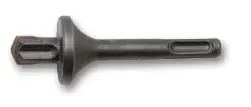
| Cat. No. | Accu-Bit Size | Drill Diameter | Drill Depth | Pack Qty. |
| PPA2431720 | 5/8″ x 3/4″ stop Drill Bit – PT Anchor | 5/8″ | 3/4″ | 1 |
SDS Plus Setting Tool for DEWALT Mini-Undercut+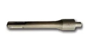
| Cat. No. | SDS Plus Setting Tool Size | Rod/Anchor Dia. | Pack Qty. |
| PFM2101720 | 3/8″ sDs+ setting Tool – PT Anchor | 3/8″ | 1 |
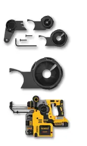
| SDS PLUS 20v Max Rotary Hammer and Accessories | ||
| Cat. No. | Description | Pack Qty. |
| DWH003sBH* | stop Bit Head Nozzle Kit | 1 |
| DWH002sBH* | stop Bit Head replacement 3-Pack | 1 |
| DCH273P2DHo* | 20V MAX Xr® Brushless 1″ L-shape sDs Plus rotary Hammer Kit With on Board Dust Extractor | 1 |
| *ADD “DH” for on-Board Dust Extraction | ||


