
kinetic technologies KTS1677A 5ARMS Vbus Current Sink Protection Load Switch
Product Information
KTS1677A 5ARMS VBUS Current-Sink Protection Load Switch
The KTS1677A is a load switch with 5A maximum continuous current rating and VBUS current-sink protection. It is designed to protect the input voltage (VBUS) from overvoltage, undervoltage, and reverse voltage conditions. The load switch can be controlled using an enable pin (EN) and has a low on-resistance of 20mΩ (typical).
Product EVAL Kit Physical Contents
| Item # | Description | Quantity |
|---|---|---|
| 1 | KTS1677A EVAL Kit fully assembled PCB | 1 |
| 2 | XT30-to-Banana power cables, red/black pair | 2 pairs |
| 3 | Anti-static bag | 1 |
| 4 | KTS1677A EVAL Kit Quick Start Guide — printed 1-page (A4 or US Letter) | 1 |
| 5 | EVAL Kit box | 1 |
User-Supplied Equipment
The user needs a VIN bench supply to power the KTS1677A EVAL kit.
Product Usage Instructions
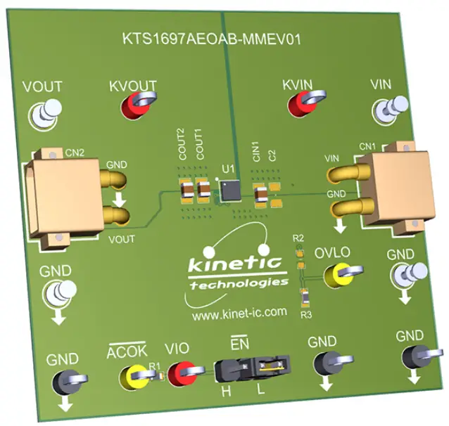
- Set the jumpers to default: EN = L (A-Version).
- Connect one pair of XT30-to-Banana power cables to the XT30 connector at VIN and GND (right edge of EVAL Kit).
- Before connecting the EVAL Kit to the VIN bench supply, turn on the supply and adjust the voltage as per the requirements.
Note: For detailed information on KTS1677A and its features, refer to the IC Landing Page and EVAL Kit Landing Page provided in the QR links for documents section of the user manual.
EVAL Kit Physical Contents
| Item # | Description | Quantity |
| 1 | KTS1677A EVAL Kit fully assembled PCB | 1 |
| 2 | XT30-to-Banana power cables, red/black pair | 2 pairs |
| 3 | Anti-static bag | 1 |
| 4 | KTS1677A EVAL Kit Quick Start Guide — printed 1-page (A4 or US Letter) | 1 |
| 5 | EVAL Kit box | 1 |
QR Links for Documents
| IC Landing Page | EVAL Kit Landing Page |

| 
|
User-Supplied Equipment
- Bench Power Supply for VIN – 5V/9V/15V/20V and 0.5A/1.5A/3A/5A, as needed for the intended application. For testing over-voltage protection and withstand voltage, a 29V adjustable bench power supply is preferred.
- Digital Multimeter – used to measure input/output voltages and currents.
Quick Start Procedures
- Set Jumpers to default: ̅E̅̅N̅ = L (A-Version).
- Connect one pair of XT30-to-Banana power cables to the XT30 connector at VIN and GND (right edge of EVAL Kit).
- Before connecting the EVAL Kit to the VIN bench supply, turn on the supply and adjust the voltage as close to 0V as possible. Then turn off the supply. While off, connect the banana ends of the XT30-to- Banana power cables to the VIN bench supply.
- Turn on the VIN bench supply and very slowly ramp its voltage to an appropriate voltage, such as 5, 9, 12, 15, or 20V. While ramping VIN slowly, use the bench supply’s output current indication (or a digital multimeter) to monitor the VIN current. If the current becomes high, reduce the VIN voltage quickly to prevent damage. Then inspect the setup for any wiring errors.
- With valid VIN voltage, use a digital multimeter to check the output voltage between the KVOUT and GND terminals on the EVAL Kit. It should be nearly the same as the input voltage.
- Use a digital multimeter to check the “ideal diode” droop regulation voltage between the KVIN and KVOUT terminals on the EVAL Kit. At no-load and light-load conditions, it should be close to 1mV.
- Use a digital multimeter to check the no-load supply current at VIN. Consult the KTS1677A datasheet for the expected current range at the VIN voltage condition in use. For conditions of VIN = 5.0V, ̅E̅̅N̅ = L, and no-load, it should be close to 130UA.


