![]() KTS1601EUM-1-MMEV01 2A Slew Rate Controlled Load Switch with Reverse Blocking
KTS1601EUM-1-MMEV01 2A Slew Rate Controlled Load Switch with Reverse Blocking
User Manual
Brief Description
The KTS1601 Evaluation (EVAL) Kit is used to demonstrate and evaluate the KTS1601 functionality, performance, and PCB layout. The kit includes a fully assembled and tested PCB with the KTS1601 IC installed, and a printed copy of the Quick Start Guide (also contained within this document).
Ordering Information
| Part Number | Description | IC Package |
| KTS1601EUM-1-MMEV01 | KTS1601 EVAL Kit | WLCSP-4 |
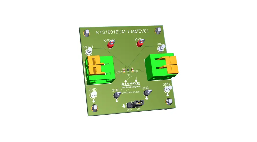
3D CAD Image
EVAL Kit Physical Contents
| Item # | Description | Quantity |
| 1 | KTS1601 EVAL Kit fully assembled PCB | 1 |
| 2 | Anti-static bag | 1 |
| 3 | KTS1601 EVAL Kit Quick Start Guide — printed 1-page (A4 or US Letter) | 1 |
| 4 | EVAL Kit box | 1 |
QR Links for Documents
| IC Datasheet | EVAL Kit Landing Page |
 |  |
| https://www.kinet-ic.com/KTS1601/ | https://www.kinet-ic.com/kts1601eaum-mmev01/ |
User-Supplied Equipment
Required Equipment
- Bench Power Supply for VIN – 5V and 0.5A/2A, as needed for the intended application.
- Digital Multi meter – one or more, used to measure input/output voltages and currents.
Optional Equipment
- Oscilloscope – for dynamic testing of voltages (and currents with a current probe, if available).
- Load – either an e Load, power resistors, or an actual system load.
- Additional Digital Multi meters
Recommended Operating Conditions
| Symbol | Description | Value | Units |
| IN, OUT, EN | Input voltage, Enable Input Voltage, Output Voltage to GND | -0.3 to +6.0 | V |
| ISW | Maximum Continuous Switch Current (IMAX) | 2 | A |
Jumper Descriptions
| Designator | Name | Description | Default |
| P1 | EN | Active-High Enable Input GND: Shutdown Mode – switch disabled VIN: Enable Mode – normal switch operation | VIN |
Quick Start Procedures
- Set Jumper to default: EN = VIN (High)
- Connect one pair of Banana-to-clip power cables to the test points at VIN and GND (right edge of EVAL Kit).
- Before connecting the EVAL Kit to the VIN bench supply, turn on the supply and adjust the voltage as close to 0V as possible. Then turn off the supply. While off, connect the banana ends of the Banana to clip power cables to the VIN bench supply.
- Turn on the VIN bench supply and very slowly ramp its voltage to an appropriate voltage of 4.5V. While ramping VIN slowly, use the bench supply’s output current indication (or a digital multi meter) to monitor the VIN current. If the current becomes high, reduce the VIN voltage quickly to prevent damage. Then inspect the setup for any wiring errors.
- With valid VIN voltage, use a digital multi meter to check the output voltage between the KVOUT and GND terminals on the EVAL Kit. It should be nearly the same as the input voltage.
- Use a digital multi meter to check the no-load supply current at VIN. Consult the KTS1601 datasheet for the expected current range at the VIN voltage condition in use. For conditions of VIN = 4.5V, EN = VIN,and no-load, it should be close to 6A.
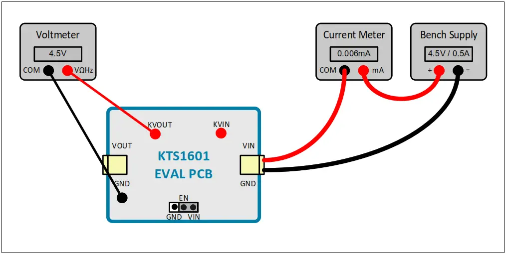
Typical Test Setup Diagram
As an example, use the following test setup to measure items 5 and 6 in the Quick Start Procedures.
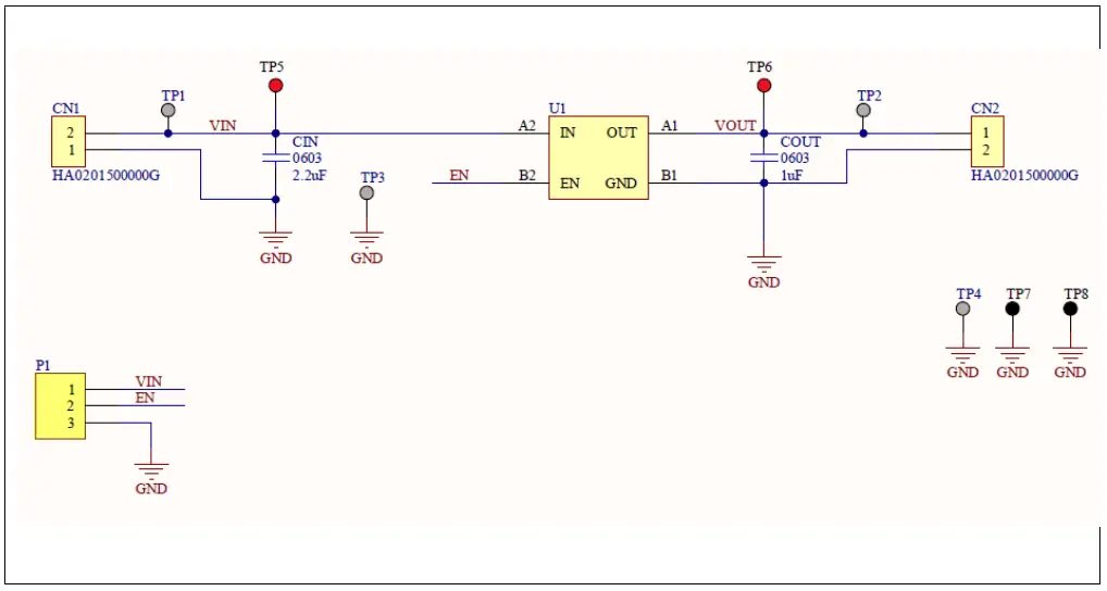
Electrical Schematic
Bill of Materials (BOM)
| Quantity | Designator | Description | Value | Package | Manufacturer | Manufacturer Part Number | Digikey Part Number | Mouser Part Number |
| 1 | CIN | CAP CER 2.2uF 10V X7R 0603 | 2.2uF | 0603 | Murata | GRM188R71A225KE1 5D | 490-4520-1-ND | 81- GRM188R71A225KE15 |
| 2 | CN1, CN2 | TERM BLK 2P SIDE ENT 5.08MM PCB | Amphenol Anytek | HA0201500000G | 609-4543-ND | 649- 2020303H021B01LF | ||
| 1 | COUT | CAP CER 1uF 16V X5R 0603 | 1uF | 0603 | Murata | GRM188R61C105KA1 2D | 490-10479-1-ND | 81- GRM188R61C105KA2 D |
| 1 | P1 | Header with jumper connects pin 1 to pin 2 | TH | Sullins | PREC003SAAN-RC | S1012EC-03-ND | ||
| 4 | TP1, TP2, TP3, TP4 | TERM TURRET SINGLE L=5.56MM TIN | 1POS | Keystone | 1502-2 | 36-1502-2-ND | 534-1502-2 | |
| 2 | TP5, TP6 | PC TEST POINT MULTIPURPOSE RED | Through Hole | Keystone | 5010 | 36-5010-ND | 534-5010 | |
| 2 | TP7, TP8 | PC TEST POINT MULTIPURPOSE BLACK | Keystone | 5011 | 36-5011-ND | 534-5011 | ||
| 1 | U1 | 2.0A Slew Rate Controlled Load Switch with Reverse Blocking | WLCSP-4 | Kinetic Technologies | KTS1601EUM-1-TR |
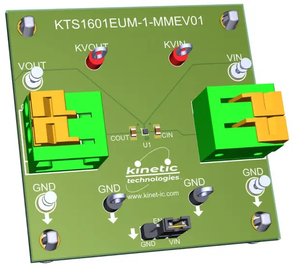
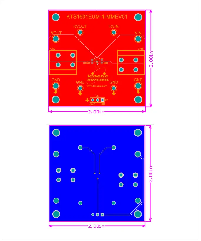
Printed Circuit Board (PCB)
Additional Test Procedures
- Testing with load and measure the KTS1601 load switch on-resistance RDS(ON)
a. Use power cable pair to apply loads, for example 10Ω, from VOUT to GND.
b. Use multi meters and an oscilloscope to make DC and transient measurements as desired.
c. Measure the output current between the VOUT terminal and the resistive load.
d. Measure the voltage between the test points KVIN and KVOUT (VIN/VOUT Kelvin connections).
e. The switch resistance can be calculated with the formula: RDS(ON) = (VKVIN – VKVOUT)/output current.
Important Notices
Legal notice
Copyright © Kinetic Technologies. Other names, brands and trademarks are the property of others.
Kinetic Technologies assumes no responsibility or liability for information contained in this document. Kinetic Technologies reserves the right to make corrections, modifications, enhancements, improvements, and other changes to its products and services at any time and to discontinue any product or services without notice. The information contained herein is believed to be accurate and reliable at the time of printing.
Reference design policy
This document is provided as a design reference and Kinetic Technologies assumes no responsibility or liability for the information contained in this document. Kinetic Technologies reserves the right to make corrections, modifications, enhancements, improvements, and other changes to this reference design documentation without notice.
Reference designs are created using Kinetic Technologies’ published specifications as well as the published specifications of other device manufacturers. This information may not be current at the time the reference design is built. Kinetic Technologies and/or its licensors do not warrant the accuracy or completeness of the specifications or any information
contained therein.
Kinetic Technologies does not warrant that the designs are production worthy. Customer should completely validate and test the design implementation to confirm the system functionality for the end use application.
Kinetic Technologies provides its customers with limited product warranties, according to the standard Kinetic Technologies terms and conditions.
For the most current product information visit us at www.kinet-ic.com
Life support policy
LIFE SUPPORT: KINETIC TECHNOLOGIES’ PRODUCTS ARE NOT DESIGNED, INTENDED, OR AUTHORIZED FOR USE AS COMPONENTS IN LIFE SUPPORT DEVICES OR SYSTEMS. NO WARRANTY, EXPRESS OR IMPLIED, IS MADE FOR THIS USE. AUTHORIZATION FOR SUCH USE SHALL NOT BE GIVEN BY KINETIC TECHNOLOGIES, AND THE PRODUCTS SHALL NOT BE USED IN SUCH DEVICES OR SYSTEMS, EXCEPT UPON THE WRITTEN APPROVAL OF THE PRESIDENT OF KINETIC TECHNOLOGIES FOLLOWING A DETERMINATION BY KINETIC TECHNOLOGIES THAT SUCH USE IS FEASIBLE. SUCH APPROVAL MAY BE WITHHELD FOR ANY OR NO REASON.
“Life support devices or systems” are devices or systems which (1) are intended for surgical implant into the human body, (2) support or sustain human life, or (3) monitor critical bodily functions including, but not limited to, cardiac, respirator, and neurological functions, and whose failure to perform can be reasonably expected to result in a significant bodily injury to the user. A “critical component” is any component of a life support device or system whose failure to perform can be reasonably expected to cause the failure of the life support device or system, or to affect its safety or effectiveness.
SUBSTANCE COMPLIANCE
Kinetic Technologies IC products are compliant with RoHS, formally known as Directive 2002/95/EC of the European Parliament and of the Council of 27 January 2003 on the restriction of the use of certain hazardous substances in electrical and electronic equipment. However, this evaluation kit does not fall within the scope of the EU directives regarding electromagnetic compatibility, restricted substances (RoHS), recycling (WEEE), FCC, CE or UL, and may not meet the requirements of these or related directives. To the best of our knowledge the information is true and correct as of the date of the original publication of the information. Kinetic Technologies bears no responsibility to update such statement.
![]() Kinetic Technologies Confidential
Kinetic Technologies Confidential
February 2023 – EUM-0007-01


