![]() MV electrical network management
MV electrical network management
Easergy T300 range
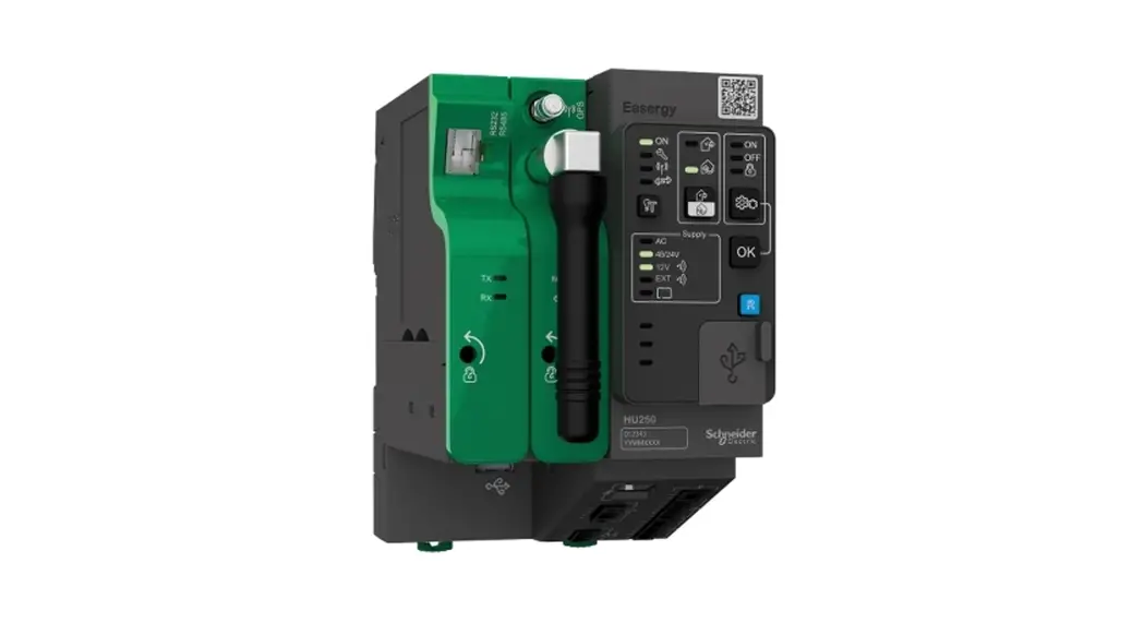
HU250
Control and communication unit installation guide

NOTE
Electrical equipment must be installed, operated, serviced, and maintained only by qualified personnel. No responsibility is assumed by Schneider Electric for any consequences arising out of the use of this material.
A qualified person is one who has skills and knowledge related to the construction, installation, and operation of electrical equipment and has received safety training to recognize and avoid the hazards involved.
| Port | Characteristics | Description | |||
3 Local communication ETH1 Ethernet port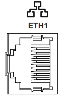 | 10/100 Base-T RJ45 connector | An Ethernet port is used for the link to an external device in the MV substation or for connection to a PC. Isolation: 2 HVAC | |||
4 Remote communication ETH2 Ethernet port | 10/100 Base-T RJ45 connector | An Ethernet port is used for the remote link to the control center, via a modem or router. Isolation: 4 HVAC | |||
5 Double Ethernet ports LAN 1 and 2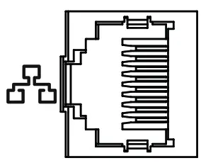 | 10/100 Base-T RJ45 connectors | Double ports are dedicated to internal communication between T300 modules or for connection to a PC.Isolation:2kVAC10 Ethernet jumpers (Ref: EMS59528) provide as accessories allow the internal Ethernet connection between the modules HU250, SC150, and LV150. | |||
6 RS485 port1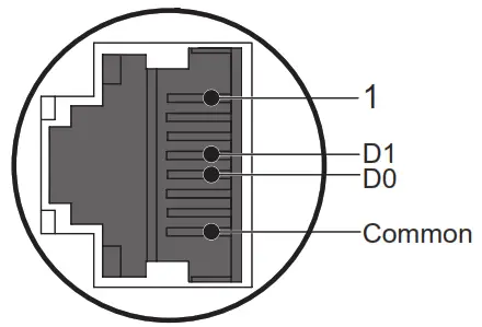 | RJ45 connector capable of including the following connections: | Port dedicated to internal Modbus communication with the Easergy PS50 power supply module or any other device communicating in Modbus protocol Speed: up to 38400 baud Isolation: 2 HVAC | |||
| 7 WI-FI port | Dual-band concurrent WI-FI (2.4GHz/5GHz) | WI-FI hotspot with security for local connection with a PC, tablet, or smartphone to:b The T300’s embedded Web server b The Easergy Builder advanced configuration tool | |||
| Parameter | Value | Unit | |||
| Operating frequency range | 2400 – 2483.5 | MHz | |||
| Maximum transmitted power | 18.2 | dBm | |||
| 8 Expert USB port | Mini USB connector | Mini USB port dedicated to equipment maintenance (reserved for qualified personnel). Requires the installation of a specific driver. | |||
| 9 Host USB port | A type of USB connector | Multi-purpose USB peripheral | |||
NOTICE
HAZARD OF TERMINAL DAMAGE OR INCORRECT POWER SUPPLY
- Use appropriate tightening torques for tightening connector screws (tightening torque values provided in this document).
- The digital inputs accept only dry contacts. Consequently, these inputs must not receive voltage.
- The HU250 module must be powered by a power supply of the SELV/PELV type (e.g. the PS50 module).
- The supply voltage of the HU250 module must not exceed 57.6 VDC.
Failure to follow these instructions can result in equipment damage.
Description
The HU250 module of the Easergy T300 range is the communication gateway dedicated to remote control applications for T300 units.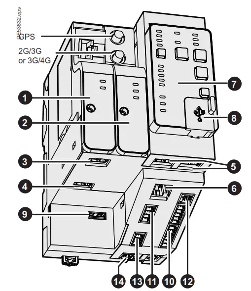
The HU250 includes the following components:
NOTICE
HAZARD OF INCORRECT CURRENT MEASUREMENTS
- Do not expose the device to conditions exceeding the electrical values specified in this document.
- Install the device vertically in an electrical cabinet, in accordance with the local regulations in force.
- Connect the product to the ground (DIN rail) to help ensure compliance with electromagnetic compatibility (EMC) limits.
- Standby protection should be provided in accordance with national and international cabling regulations.
- An appropriate electrical disconnecting device must be installed in the building in question.
- Use only the type of connector supplied as an accessory for the HU250 module (product reference: EMS59010).
- Check that the connections correspond to the recommended cables before powering up the equipment.
- Use appropriate tools to perform cabling on the connectors (suitable screwdriver, crimped end pieces, etc.).
- Strip the wires appropriately (not excessively) before connecting them to the connectors (see the recommendations in this document).
Failure to follow these instructions can result in equipment damage.
| Port | Characteristics | |||||
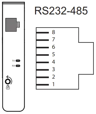 Communication ports RS232-485 *Speed: Communication ports RS232-485 *Speed: | or the remote link to the control center, customizable modem boxes including the following modems: RS232-485 modem (EMS59151) up to 115200 baud / Isolation: 2 kV I RJ45 connector including the following connections: | |||||
| PIN No. | RS232 | RS485 (2-wire) | V RS422 (4-wire) | |||
| 1 | TXD | RX00 (A) | ||||
| 2 | RXD | RXD1 (B’) | ||||
| 3 | CTS | |||||
| 4 | DTR | D1 (B) | TXD1 (B) | |||
| 5 | DSR | DO (A) | TXDO (A) | |||
| 6 | RTS | |||||
| 7 | OCD | |||||
| 8 | GND | GND | GND (C/C’) | |||
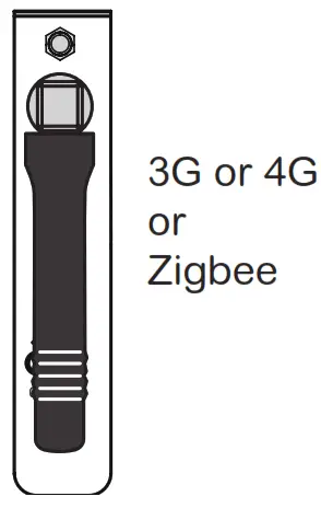
| 3G modem 4G standard (Option, | Zigbeisreceiver (Op ion, ref. EMS59152) modem with GPS time synchronization US version ref. EMS59154; EU version ref. EMS59155) (Option, ref. EMS59156) | |||||
 | – -7 Modem | Frequencies | ‘ Max1 mu transmitted power (dBm) | |||
| 3G | •Five bands UMTS/HSPA+ (WCDMA/FDD) (850/800, 900, 1900 and 2100 MHz •Quad-Band GSM (850/900/1800/1900 MHz) | 24 33 | ||||
| Note: The ports 1 and 2 can accept only one 3G or 4G modem. | ||||||
| 4G US | •Penta Band LTE: 700/700/850/AWS (1700/2100)11900 MHz: FDD-Band (13,17,5,4.2) •Tri Band UMTS (WCDMA): 850/AWS (1700/2100)/1900 MHz: FDD-Band (5.4,2) •Quad Band GSM/GPRS/EDGE: 850/900/1800/1900 MHz | 23 24 33 | ||||
| 4G EU | •Penta Band LTE: 800/900/1800/2100/2600 MHz: FDD-Band (20, 8, 3, 7, 1) •Tri Band UMTS (WCDMA): 900/1800/2100 MHz: FDD-Band (8, 3, 1) •Dual band GSM/GPRS/EDGE: 900/1800 MHz | 23 24 33 | ||||
| Zigbee receiver | Operating frequency range (IEEE 802.15.4): 2405 – 2480 MHz | 7 | ||||
| Port | Characteristics | Description | ||||||||||||||||||||||||||
10 Digital inputs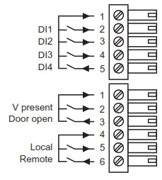 | Plug-in screw connectors:
| 8 digital inputs: 4 unallocated digital inputs (for free use) 4 dedicated digital inputs for: voltage presence (e.g. via the PS50 module) connection of a door open switch connection of an external Local/Remote switch Note: The *Door opens and *Local/Remote» dedicated digital inputs correspond to a default T300 application. They can be used differently for another application by configuration. 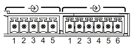 | ||||||||||||||||||||||||||
11 Digital outputs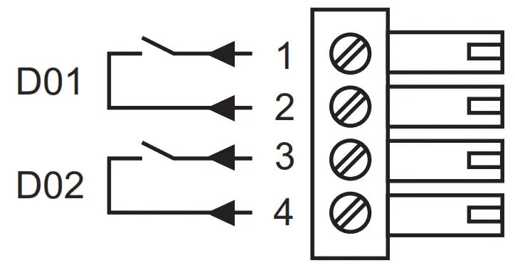 | Plug-in screw connector:
| 2 dry-contact digital outputs for free use. Breaking capacity: 2000 VA Max. voltage: 60 VDC Max. current: 2A Isolation: 2 kVAC 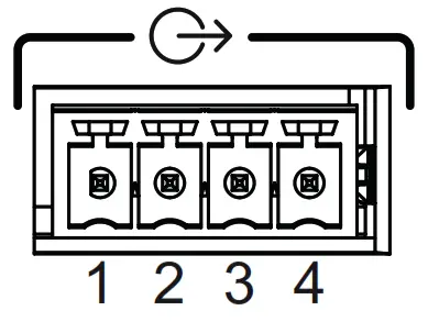 | ||||||||||||||||||||||||||
12 Analog inputs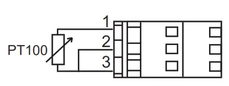 | ||||||||||||||||||||||||||||
Analog inputs | Plug-in leaf-spring connector:
| 2 analog inputs for connection of one 3 wire PT100 temperature sensor. Measurement: -55°C to 250°C (-67°F to 482°F) Resolution: 1°C (1°F) 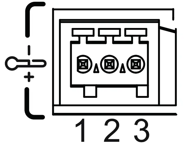 | ||||||||||||||||||||||||||
| Indicator outputs | Plug-in screw connector:
| 2 polarized indicator outputs for external indication outside the MV substation. These indicators can be assigned by configuration to fault current detection indication (directional indication). Refer to the T300 Quickstart. The voltage delivered: 5 V Max. current: 100 mA Note: These outputs are polarized. Comply with the direction of the connection. | ||||||||||||||||||||||||||
14 Power supply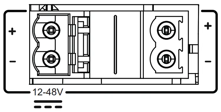 | Plug-in screw connectors:
| 2 power supply connectors connected internally, facilitating serial connections and allowing looping of power supplies between the T300 modules. (See Power Supply section). Activate Windows |
Cabling
Recommendations for the length of cable less than 2 meters.
 | 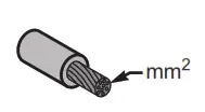 |  | ||
| 10 |  | 7 mm 0.276 in | 0.5 mm2 20 AWG | 0.22-0.25 N.m 1.9-2.2 lb-in |
| 11 |  | |||
| 13 |  | |||
| 12 |  | 8 mm 0.315 in | 0.14-0.5 mm2 26-20 AWG | _ |
| 14 | 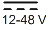 | 7 mm 0.276 in | 1-2.5 mm2 17 AWG | 0.5-0.6 N.m 4.4-5.3 lb-in |
Installation
Installing the enclosure
The HU250 module is fastened to a DIN rail. No tool is needed for mounting.
Simply clip it in order to fasten it as shown below.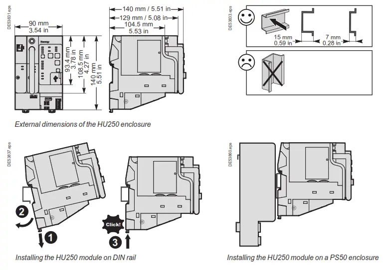
Installation of a modem box
Each modem box can be installed or interchanged easily and quickly in the HU250. The modem box is installed in the factory, but if necessary it is possible to dismount it and replace it with another type of modem. To install a modem box: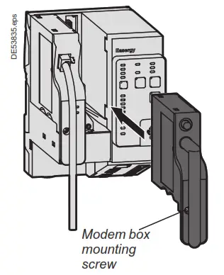
- Insert the SIM card(s) on the bottom of the modem (preferably with HU250 switched off).
- Install the modem box in the required slot on the HU250 (port 1 or port 2 slot).
- Press the front panel to insert the rear panel connector in the HU250 (be careful not to over-force during insertion).
- Tighten the screw on the front panel using a flat or Phillips-head screwdriver to fasten the modem box to the HU250.
To withdraw a modem box from its slot, perform the operation in reverse.
Note: When changing a modem box it is also necessary to have the configuration changed by an expert using the Easergy Builder advanced configuration tool. To do so, refer to the Easergy Builder user guide.
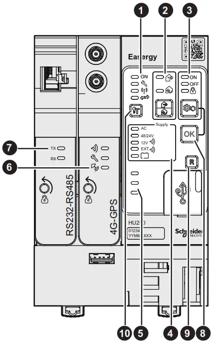
Operation
Once the HU250 has been powered up, some indicator lamps on the front panel may be lit to indicate certain operating states.
The buttons allow the user to perform actions. These indications and actions are summarized in the table below:
| Part | Description of indications and actions |
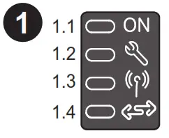
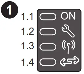 | HU250 states 1.1 HU250 operating 1.2 Equipment status 1.3 WI-Fl access operating (activated by Local mode) 1.4 Communication status with modules (SC150. LV150. PS50….). |
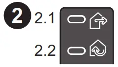
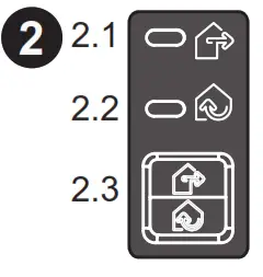 | Local/Remote 2.1 Remote position: Al local controls on switches via the SC150 module we locked (via the front panel and WI-FI) 2.2 Local position: All remote controls are locked 2.3 Push button that can be used to change LocalRemote state Note: Switching to local mode activates WI-Ft access. |
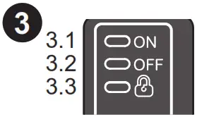
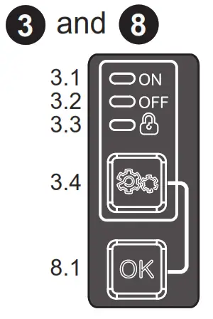 | Automatic control states and checks 3.1 Automatic control enabled 3.2 Automatic control disabled 3.3 Automatic control locked 3.4 Automatic control change-of-state button (ON/OFF). 8.1 Change-of-state enabling button. The two buttons. change of state and enabling, must be pressed simultaneously for the change of state to take place. This change is performed simultaneously on al the T300 modules using automatic control functions. Note: Change of state of the automatic control system by means of the buttons is possible only in Local mode. |
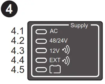
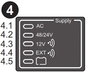 | Power supply 4.1 Mains power supply operating 4.2 48 V/24 V motor pack power supply operating 4.3 Transmission equipment power supply operating 4.4 Overconsumption of Transmission equipment power supply 4.5 Battery status Note: These states correspond to information retransmitted by the PS50 module ve Modbus communication between modes. When another type of power supply module is used, these indicators can be customized by configuration via the Energy Builder advanced configuration toot |
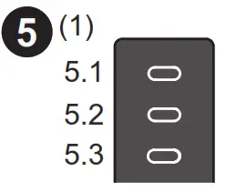
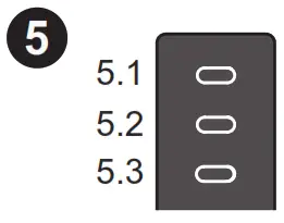 | Customizable indicator lamps 5.1;5.2;5.3 3 unassigned indicator lamps configurable for indication of customized states. Note: Customization of these indicators is performed via the Easergy Builder advanced configuration tool. Refer to the Ouch start manual. |
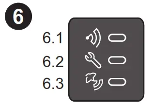
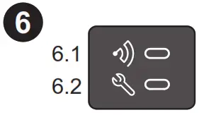
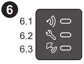 | 3G or 46 or Zigbee receiver modem box indicator lamps 0.1 Indicator of activity on me mobile or Igbee network This indicates ( Sashes n pamculardunng research of network or a data transfer. and. for Zigbee protocol, when commissioning the device. 02 Modem status rickey lamp: lights for a SIN card status onto indicate a problem of correction to the noble or ligne network (kw level of reception I 13.3 GPS signal reception status indicator (only for modem boxes with GPS). |
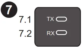
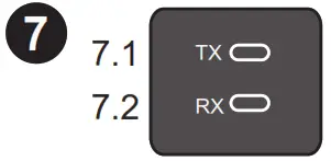 | R8232-RS485 modem box indicator 7.1 TX: RS232/RS485 data transmission indicator lamp. 7.2 RX: RS232/RS485 data reception indicator lamp. |
 | Reset 9.1 Reset button reinitializing all fault current indications on all the SC150 modules and automatic control locking. |
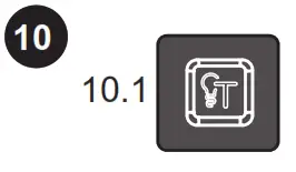 | Indicator test 10.1 Indicator test button for the forced setting of lighting of all indicator lamps on the front panel of the T300 modules and the external indicator lamp. Makes it possible to detect any anomaly concerning the indicator lamps. |
Note: Refer to the table opposite for the meaning of the flashing states and the various possible colors for indicator lamps. Some indicators can be customized by configuration.
3G or 4G modem
This modem allows a SIM card to be inserted in one of the two available SIM card slots, without there being any difference at the operating level.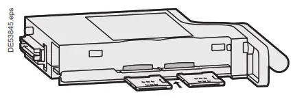 The GPS and GSM antenna connectors are accessible on the front of the modem.
Mounting the GPS antenna:
- Attach the GPS antenna to the wall of the substation (preferably outside).
- Connect the antenna cable to the modem connector marked «GPS».
Note: The GSM antenna requires no outside mounting. It is a short antenna connected to the modem itself. This antenna is installed in the factory.
DANGER
HAZARD OF ELECTRIC SHOCK, EXPLOSION, OR ARC FLASH
- Wear your personal protective equipment (PPE) and comply with safe electrical work practices. See NFPA 70E in the USA or applicable local standards.
- Only qualified persons should install this equipment. Such work should be performed only after reading this entire set of instructions.
- Switch off the electric power supply of the HU250 and of all the devices to which the HU250 is connected before any handling or replacement operation.
- Always use a properly rated voltage-sensing device to confirm that all power is off.
Failure to follow these instructions will result in death or serious injury.
Power supply
The HU250 includes two connectors to connect the power supply. These two connectors are connected together internally in the HU250. Having two power supply connections can facilitate the connection between the modules. No strapping is necessary. Connect the HU250 as shown in the following diagram.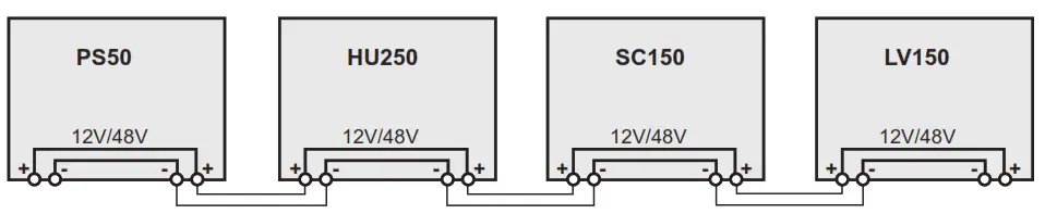
Parameters setup
Installation of the HU250 module requires no parameters setup. This is performed during the commissioning/ configuration stages. Refer to the User manual and the T300 Quick start for any further information.
Identification
The serial number of the HU250 is formed as follows: Year – Week – Work order e.g. 15340265 (265th product manufactured, week 34 of the year 2015)
Grounding
The HU250 module must be connected to the ground via the mounting DIN rail. The DIN rail helps ensure electrical continuity (preferably use a DIN rail in 304L stainless steel to withstand the climatic conditions).
NOTICE
HAZARD OF INCORRECT CURRENT MEASUREMENTS
- The DIN rail on which the HU250 is installed must be grounded and of metallic type and must comply with electrical continuity in all climatic conditions.
- If the HU250 is installed on a PS50 power supply module, the grounding of the module is done via the PS50’s DIN rail, which must be grounded via a dedicated terminal near the PS50 power input connector. Refer to the Installation Guide of the PS50 power supply.
Failure to follow these instructions can result in equipment damage.
For HU250: Hereby, Schneider Electric declares that the radio equipment of the type communication gateway is in compliance with directive 2014/53/EU. The full text of the
EU declaration of conformity is available at the following internet address: https://www.schneider-electric.com/en/download/document/HU250_RED_DoC/.
For modem boxes: Hereby, Schneider Electric declares that the radio equipment of type cellular modem is in compliance with directive 2014/53/EU. The full text of the EU declaration of conformity is available at the following internet address: http://www.schneiderelectric.com/en/download/document/K7_RED_DoC/.
Indicator lamp states
| Indicator state | Flashing | Steady | Unit | |||
| Red | Green | Red | Green | Orange | ||
 | Boot – – – | – – – | Fault Major Fault Fault Fault | OK -ON | Can fault Minor fault In progress | -OK OFF OK |
 | – – | – – | -Local | Remote | – – | Local Remote |
 | – | – | OFF | ON- | -Locked | OFF ON Non-locked |
 | – | – | AC OFF Fault Fault Fault | Fault-ZOXXXY 00000 4 | – | |
 | – – | – – | – . – | ON ON ON | OFF OFF OFF | |
 | – – | Active Active and sync | – Fault . | – _ No sync | – – | Inactive OK Deactivated |
 | – | conlinsson- LNG | _ Fault | OK | – | Inactive OK |
 | . | Trans: nano Renewing | . | – | Inactive inactive | |
(1) Indicators are customizable by configuration. Only default values are shown.
Note: The indications in bold letters correspond to normal operation (first power-up without the existence of a potential issue indication).
NOTE
Easergy HU250, FCC ID: 2AHHK-EASERGYHU250
Easergy GSM/3G modem box contains FCC ID: QIPPHS8-P
This equipment has been tested and found to comply with the limits for a Class B digital device, pursuant to part 15 of the FCC Rules. These limits are designed to provide reasonable protection against harmful interference in a residential installation. This equipment generates, uses, and can radiate radio frequency energy and, if not installed and used in accordance with the instruction, may cause harmful interference to radio communications. However, there is no guarantee that interference will not occur in a particular installation. If this equipment does cause harmful interference to radio or television reception which can be determined by turning the equipment off and on, the user is encouraged to try to correct the interference by one or more of the following measures:
- Reorient or relocate the receiving antenna.
- Increase the separation between the equipment and receiver.
- Connect the equipment to an outlet on a circuit different from that to which the receiver is connected.
- Consult the dealer or an experienced radio/TV technician for help.
This device complies with FCC RF radiation exposure limits set forth for the general population. This device must be installed to provide a separation distance of at least 20cm from all persons and must not be co-located or operating in conjunction with any other antenna or transmitter.
Schneider Electric
35 rue Joseph Monier
92500 Rueil Malmaison – France
Phone: +33 (0)1 41 29 70 00
www.schneider-electric.com
© 2015-2019 Schneider Electric. All Rights Reserved.
NHA77925-08
As standards, specifications, and designs change from time to time, always ask for confirmation of the information given in this publication.
Publication: Schneider Electric
Production: Schneider Electric
Printing: Schneider Electric
Made in France![]() This document was printed on environmentally friendly paper
This document was printed on environmentally friendly paper


