![]() PAW-TD23B6E5 Combo Multifunction Hot Water Tank
PAW-TD23B6E5 Combo Multifunction Hot Water Tank
Instruction Manual
Dear customer
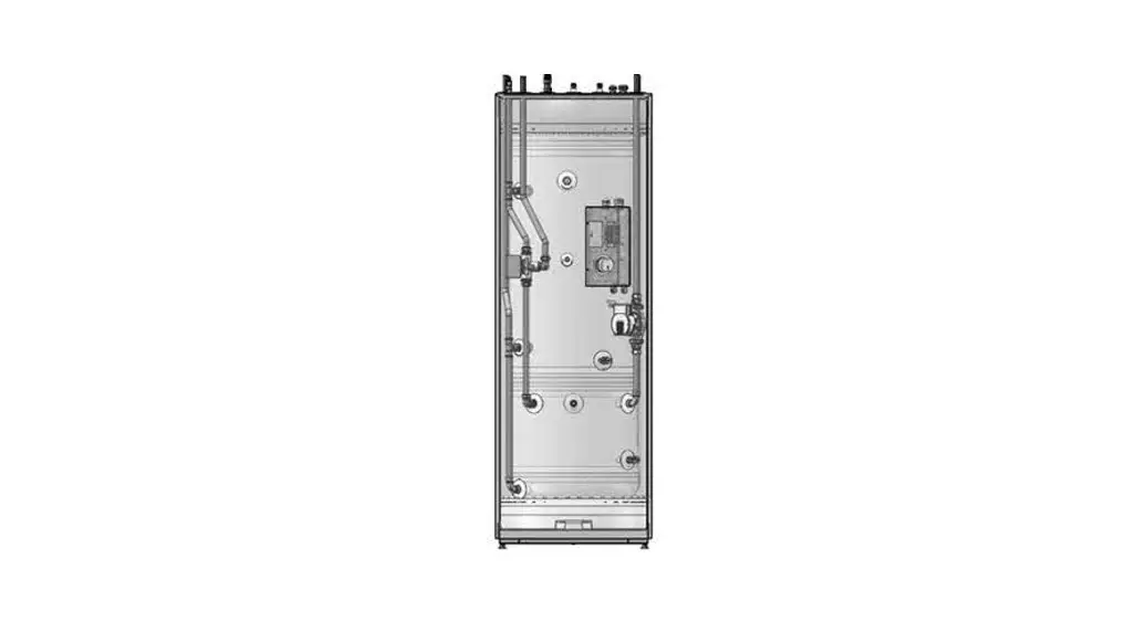
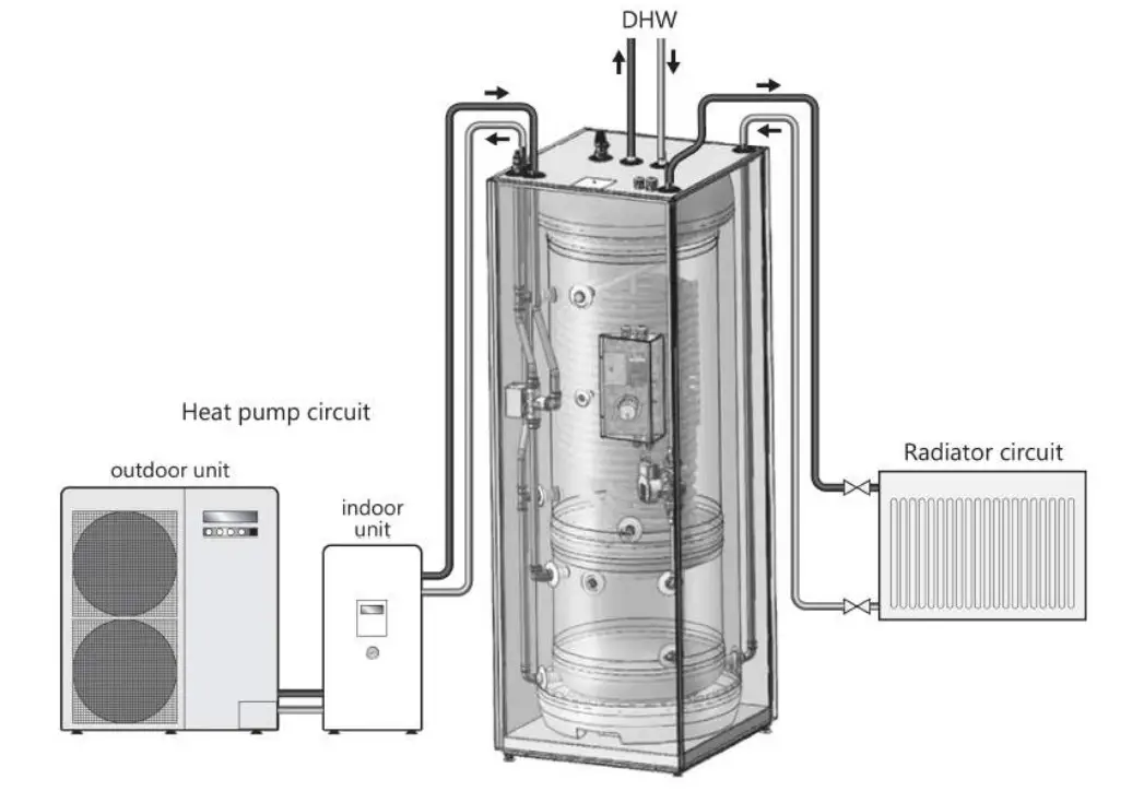
PAW-TD2386E5 is a high-grade stainless steel tank-in-tank unit with high performance and very low heat losses, intended to supply the household with domestic hot water and heat ing to radiators/underfloor heating.
The unit is insulated with 50 mm, of 4th gen PUR insulation material, reducing heat losses to a minimum. The 230L domestic hot water tank with a built-in large heating coil will sup ply sufficient hot water for a normal household, while the 60L buffer tank reduces the number of starts and stop sequences for the air/water heat pump. This increases the heat pump lifespan, and energy efficiency and provides greater comfort.
The tank-in-tank technology also reduces the total footprint of the system.
SAFETY INSTRUCTIONS
1.1 General information
- Read the following safety instructions carefully before installing, maintaining or adjusting the water heater.
- Personal injury or material damage may result if the product is not installed or used in an intended manner
- Keep this manual and other relevant doc uments where they are accessible for fu future reference.
- The manufacturer assumes compliance (by the end-user) with the safety, oper dating, and maintenance instructions sup plied and (by the installer) with the fitting manual and relevant standards and regu lactions in effect at the date of installation.

Symbols used in this manual:
| Could cause serious injury or death | |
| Could cause minor or moderate injury a. damage to property | |
| DO NOT | |
| DO |
![]() CAUTION
CAUTION
Incorrect repairs may lead to danger for users. Only trained and qualified technicians are author ised to install, move, modify or repair this product.
The warranty does not apply if the applicable regulations are not complied with.
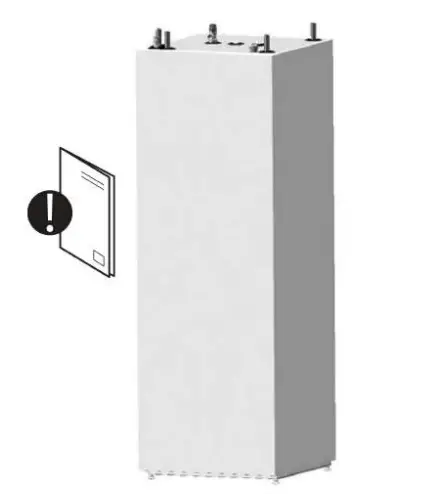
The tank must not be stored outdoors before installation.
Always wear gloves during installation or repair. Touching the pipes may lead to hot or cold burns.![]() This document should be kept in a suitable place where it is accessible for future reference.
This document should be kept in a suitable place where it is accessible for future reference.
1.2 Safety instructions for users
| The overflow from the Temperature & Pressure relief valve must NOT be sealed or plugged. | |
| The product must NOT be covered. Do NOT place foreign objects near or on the product. | |
| The product must NOT be modified or changed from its original state. | |
| Children must NOT play with the product or go near it without supervision. | |
| The product should be filled with water before the power is switched on. | |
| Maintenance/settings should only be carried out by persons over 18 years of age, with sufficient understanding. | |
| The product must not be exposed to frost, over-pressure, over-voltage or chlorine treat ment. See warranty conditions. | |
| Maintenance/settings should not be carried out by persons of diminished physical or mental capacity unless they have been instructed in the correct use by someone respon sible for their safety. | |
1.3 Safety instructions for installers
| WARNING | |
| The overflow from the Temperature & Pressure relief valve must NOT be sealed or plugged. | |
| Any overflow pipe from the safety valve must be installed uninterruptable and frost-free with a fall to the drain/gully. | |
| The electrical wiring diagram in this manual must be followed. No optional wiring is al lowed. All work on electrical systems must be performed by an authorized installer. | |
| The mains cable should withstand 90€. A strain reliever must be fitted. | |
| The product must be filled with water before the power is switched on. | |
| The product must be filled with water before the power is switched on. | |
| For the buffer tank – a closed pressurized system of installation – it is obligatory to install a safety valve with rated pressure of max. 0.3 MPa (3 bar), which prevents the elevation of pressure in the buffer tank by more than 0.1 MPa (1 bar) above the rated pressure. This safety valve must be supplied and installed separately and is not part of this product. To ensure proper functioning of the safety valve, annual control to remove any blockage of the outlet shall be performed. | |
| CAUTION | |
| The product should be placed in a room with a drain. | |
| The product should be properly aligned vertically and horizontally, on a floor surface suitable for the total weight of the product when in operation. See table 2.4. | |
| The product must have a service clearance of 120 cm in front of the cover/ SO cm on top. | |
PRODUCT DESCRIPTION
Product identification
Identification details can be found on the type plate fixed to the product. It contains product information and other useful data.
The product is designed and manufactured in accordance with
| Safety standard | EN 60335-1 |
| Safety standard | EN 60335-2-21 |
| Welding standard | EN 1IS0 3834-2 |
| Pressure vessel standard | EN 12897 |
2.2 Intended use
The product is designed to supply domestic hot water in a central heat combination with ing and cooling system. The product has been designed to be connected to an external heat pump.
2.3 CE marking![]() The CE mark shows that the product complies with the relevant Directives. See Declaration of Conformity at the manufacturers’ website for more information.
The CE mark shows that the product complies with the relevant Directives. See Declaration of Conformity at the manufacturers’ website for more information.
The product complies with EU directives
| Low voltage | LVD 2014/35/EU |
| Electromagnetic compatibility | EMC 2014/30/EU |
| Pressurized equipment | PED 2014/68/EU |
Any safety valve(s) used in the system shall be CE-marked and comply with PED 2014/68/EU.
Technical data
| Parameter | Unit | Description |
| Measures HxWxD | mm | 1751x599x646 |
| Weight (empty) | kq | 111 |
| Weight (full) | kq | 401 |
| Volume | liters DHW+Buffer | 230+60 |
| Electric element – effect | kW | 3. |
| Power supply | V / Phase / Hz | 230 /1/ 50 |
| Domestic hot water tank: | ||
| Volume | liters | 230 |
| Max working pressure | MPa (bar) | 1,0 (10) |
| Pressure test (bar) | MPa (bar) | 1,5 (15) |
| Max working temp | °C | 80 |
| Connections / Material | mm / EN | 022 / 1.4404 |
| Tank material | EN | 1. |
| Insulation | Material/Thickness | PUR / 50 |
| Heating coil surface | Mz | 2. |
| Energy loss at 65°C | kWh/24h | 1,25 / 0,7 |
| Buffer tank: | ||
| Volume | liters | 60 |
| Max working pressure | MPa (bar) | 0,3 (3,0) |
| Pressure test | MPa (bar) | 0,39 (3.9) |
| Max working temp | °C | 80 |
| Connections / Material | mm / EN | 022, copper |
| Tank material | EN | 1. |
| Insulation | Material/Thickness | PUR / 50 |
INSTALLATION INSTRUCTIONS
3.1 Products covered by these instructions
80341990 PAW-TD23B65
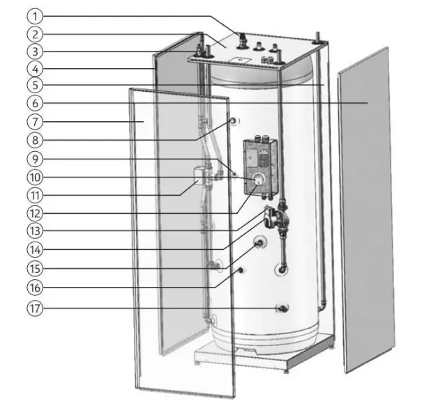
3.2 Included in delivery
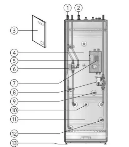
| Ref no. | Pcs. | Description |
| 1 | 1 | Air vent valve for DHW tank |
| 2 | 1 | Temperature and pressure valve (T&P) |
| 3 | 1 | Installation manual (this document) |
| 4 | 1 | DHW tank, 230L, max pressure 10.0 bar |
| 5 | 1 | Electronic box |
| 6 | 1 | 3-way valve |
| 7 | 1 | Terminal block |
| 8 | 1 | Circulation pump |
| 9 | 1 | Drain valve for DHW tank |
| 10 | 1 | Air vent valve for buffer tank |
| 11 | 1 | Buffer tank, 60L, max pressure 3.0 bar |
| 12 | 1 | Drain valve for buffer tank |
| 13 | 4 | Adjustable feet |
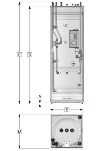
3.3 Product dimensions
All dimensions in mm.
| Product | A | B | C | D | E | F |
| NDS | 17-37 | 17-51 | 1853 | 646 | 599 |
Tolerance +- S mm. (not dimension A)
3.3.1 Important notice before installation
Make sure you’ve chosen a heat pump that suits the existing heating system and power equipment The product must also suit the nominal water flow, lift height, and size of the system. Only use lean water in the tank. If the water quality is poor the tank may be damaged. There is also a risk of corrosion and clogging if the water quality is not maintained, The water quality must not exceed these values:
| Chloride content | < 100 mg/l |
| Total Dissolved Solids | < 200 mg/l |
| pH level | >60/<9.5 |
Should the water quality exceed the above pa parameters, a sacrificial anode may be installed in the plugged G3/4″ internal connection in the DHW tank. The anode must be in compliance with local regulations, and fitted by an authorized installer before the system has been filled with water. When the sacrificial anode is installed, the water quality must not exceed these values.
| Chloride content | < 250 mg/l |
| Total Dissolved Solids | < 500 mg/l |
| pH level | >6.0/<9.5 |
3.3.2 Pipe connections and valves
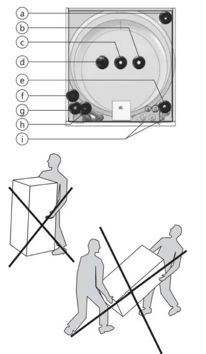
| Ref. | Dim. | Description |
| a | 22 | Radiator circuit return |
| b | 22 | Domestic cold water in |
| c | 22 | Domestic hot water out |
| d | 3/4″ | Temperature and pressure valve (T&P) |
| e | o22 | Radiator circuit flow |
| f | 22 | Heat pump circuit return |
| g | 1/8″ | Air vent valve for heating system |
| h | 22 | Heat pump circuit flow |
| DN15 | Drain valves (DHW tank & buffer tank) |
3.3.3 Transport and unpacking
The product should be transported carefully, with packaging. Also please note:
The product is very heavy and should not be lifted by one person alone.
Do not transport the unit horizontally. This can cause damage or failure.
To avoid hand injury, wear gloves when moving the product and/or while remov ing the packaging.
Be careful not to damage the product while removing the packaging.
To avoid damage an installed tank must be drained before moving.
![]() CAUTION
CAUTION
Pipe stubs, valves, etc. should not be used to lift the product as this could cause malfunctions.
3.4 Requirements for installation, location and positioning
| CAUTION | |
| The product shall be placed in a room with a drain to avoid any damage in case of water escapes from the product. | |
| The product must be placed in an area that is dry, clean, free of vapor, volatile oils, smoke and gases to avoid any damage to the internal parts of the product | |
| The product shall be placed in a dry and permanently frost-free position | |
| The product shall be placed on a floor surface suitable for the total weight of the product when in operation. See product data plate. | |
| Install the tank unit as close to the heat pump as possible. This limits the necessary vol ume of coolant (due to pipe length) | |
| The product must have a service clearance of 120 cm in front of the cover /50 cm on top | |
| The product shall be easily accessible in the home for servicing and maintenance. | |
3.5 Pipe installation
The domestic hot water tank (upper) is designed to be permanently connected to the main water supply. The buffer tank (lower) is designed to be permanently connected to the heating system, with max. pressure 3 bar /0.3 MPa. A separate safety valve with rated opening pressure max. 3.0 bar must be installed in the heating system. Approved pipes of the correct size should be used for installation The relevant standards and regu lations must be followed.
3.5.1 hot water Heating and Domestic
Use connectors that reduce the transfer of vibration, and can withstand the water temperature and pressure. To avoid “taps” in the heating system, the pipes must be able to withstand temperature differences.
3.5.2 Pipe connection dimensions
- Place the unit in the desired position. Adjust the unit to a level position by using the adjust able feet.
The tank must be leveled before it is connected and filled with water. Remove the front cover, see pt. 3.5.4 - Flush/clean the existing heating system care fully to avoid contaminating the particle filter.
- Connect the domestic water supply. A mixing valve is recommended to avoid scalding.
- Connect the unit supply and return pipes to the existing heating system. The various pipes are marked on the top of tank S.
- Connect an escape pipe and tundish be tween the Temperature & Pressure relief valve and the floor drain
- Connect an escape pipe between the radia tor safety valve and the floor drain
- Verify if the expansion vessel is dimensioned for the heating system (approx. 10% of the total volume in the system.)
- Check the re-pressure of the expansion ves sell. The pressure depends on how high the water has to be lifted.
- Fill the domestic hot water tank before filling the buffer tank. Open a hot water tap to ventilate and allow free flow of water.
- Put the 3-way valve manually in “fill mode” {both flow way open) and open the manual/automatic air vent.
- Fill the radiator system and close the manual air vent.
- Keep the pressure within the recommended pressure range to prevent the water from escap ing through the safety valve.
Restore the 3-way valve in the automatic position - Bleed the radiators. Check the system pres sure. Fill more water to the system if needed. Repeat until all air is bled from the system.
- Check if the diverting valve switches to radia tor operation and that the radiators heat up Bleed the system once it is warm. Check for leaks in the system.
- Close the automatic air vent after approx. two weeks to prevent air from entering the system.
3.5.4 Removing the front cover
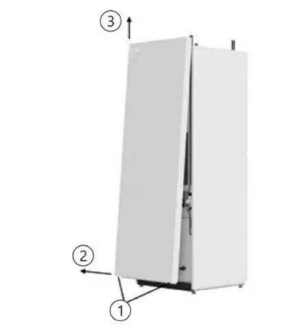
- Unscrew and remove the two screws in the lower part of the front panel (1)
- Pull out the lower part of the front approx. 100-150mm. (2)
- Grip the sides of the front panel and lift it straight up (3)
- Remove the front panel carefully to not damage the contact or the cable connection between the display and the control unit inside the front panel.
3.5.5 Pipe connection layout
3.5.6 Fitting instructions
| The product must be filled with water before the power is switched on | |
| Any overflow pipe from the T&P valve must be installed uninterruptable and frost-free with a continuous fall to the drain/all. | |
3.6 Electrical installation
Fixed electric fittings should be used for installation Any fixed electric fittings must be installed by an authorized electrician. The relevant standards and regulations must be followed.
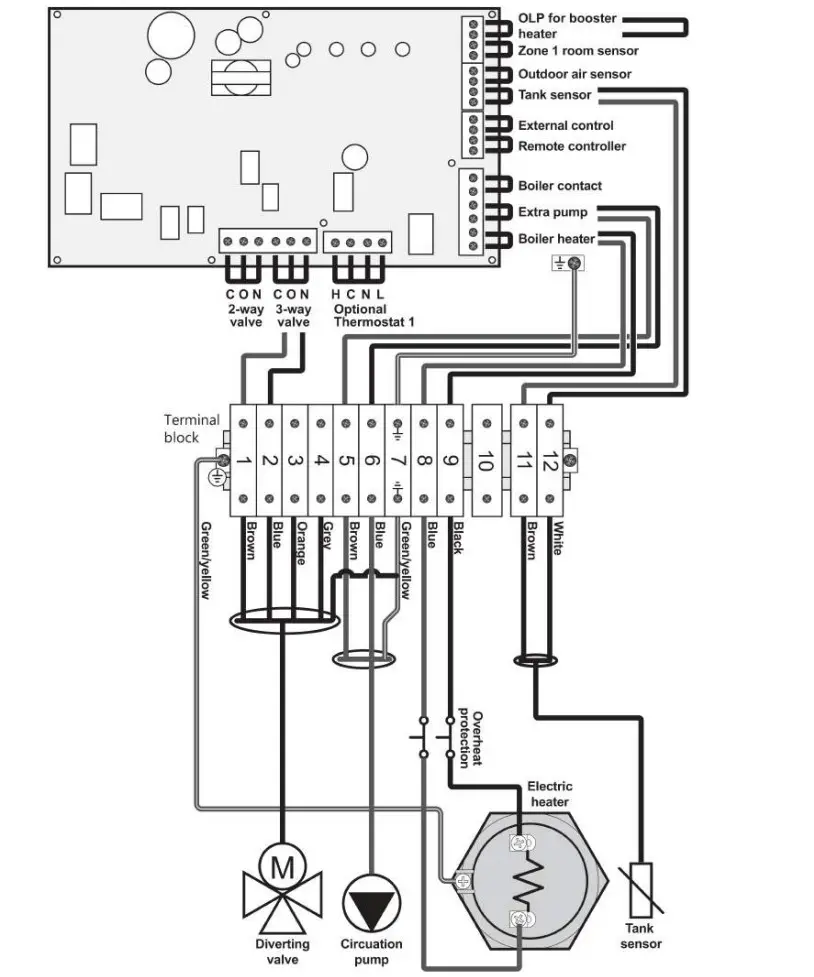
Wiring: Connect the corresponding wires from the hydro box into the electronic box inside the tank unit according to pt. 3.6.4. 0LP for Booster Heater at the HP must be jumpered.
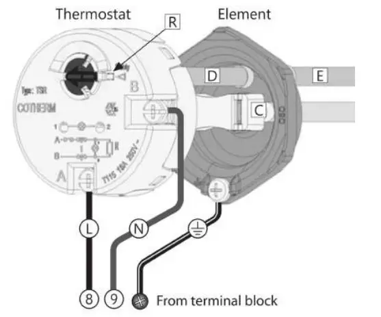
361. Backup immersion heater thermostat The immersion heater is designed as an auxil airy backup heat source. Power to the immersion heater must not be switched on until the unit is filled with water. The unit is fitted with one 2.8 kW immersion heater which is located in the electrical see pt. 5.1
Alternative thermostats must not box, or be used. Follow the wiring instructions (right) connecting the live (L) neutral (N) and earth cables as indicated.
The heater must be connected to a minimum 16 amp dedicated permanent supply complying with current local wiring regulations, isolation is required via a minimum 20 amp double pole isolation switch with a minimum 3 mm separation required
All electrical wiring should be carried out by a com patent electrician, using a heat-resistant cable (mini mum 85C), and be in accordance with the latest local Wiring Regulations.
The TSR thermostat functions solely as a safety cut-out and will operate at 85C (±5C. Should this happen, check the reasons for the thermal cut-out button being released, and when satisfied press the reset button (R).
3.62 Replacing the safety cut.out thermostat Disconnect power supply. Disconnect power cables (L) and (N) from the thermostat by loosening screws A and B. Pull the thermostat straight out of the element.
Fit the replacement thermostat by inserting the temperature sensor (D) into tube (E). Push ther most connectors firmly into the connector recep tors (C) and make sure the connectors are inserted fully into the receptors. Refit power cables (L) and (N), and tighten screws A and B to 2 Nm (+/- 0.1).
![]() WARNING
WARNING
The constant voltage is present in an electronic box. Be for any electrical work is done, the power sup ply must be disconnected and secured against activation while the work is in progress.
The thermostat must never be dismantled/opened. This will compromize its function and cause a risk of overheating. Warranty will cease.
3.6.3 Fitting instructions
| The product must be filled with water before the power is switched on. | |
| Any fixed electric fittings must be installed by an authorized electrician. The relevant stand ards and regulations must be followed. | |
| The main cable should withstand 90C. A strain reliever must be fitted | |
| The product must have a service clearance of 120 cm in front of the cover /50 cm on top. | |
| In case of damage to the mains cable, it should be replaced with a suitable mains cable from the manufacturer. | |
3.6.4 Electrical wiring diagram – main PCB of Heat Pump (Aquarea H and J series)
MAINTENANCE AND DRAINING
Maintenance should be carried out by persons over 18 years of age, with sufficient understand ing. If in doubt, contact the authorized installer.
4.1 Checking the manometer
Check manometer 2 times/year. It is particu larly important to check the manometer after a new installation, The manometer showing the pressure within the radiator system should display between 0.5-12 bar. If needed, fill the system with water until the manometer shows 1.0 bar. If you feel uncertain contact your in staller.
4.2 Checking the temperature & pressure re lief valve
Exercise the T&P relief valve once every year by turning its wheel until water is streaming out of the valve. The test is performed to safe guard the function of the valve.
The temperature variations within the system make the water expand, which may lead to wa occasionally dripping out of the overflow pipe. This is normal and no action is necessary.
| The overflow from the T&P safety valve must NOT be blocked, sealed, or plugged. | |
4.3 Checking the protective anode (if installed)
- Shut the system down using the on/off but ton on the control panel. Switch the control fuse off.
- Turn off the cold water supply to the tank
- De-pressurize the buffer tank to less than 0.5 bar
- Open a domestic hot water tap to release pressure from the tank. Leave open.
- Open the drain valve for the DHW tank. The product will drain
- Unscrew, pull out and dean the anode (A)
Measure the diameter. If the diameter of the anode is less than 10 mm it must be replaced - Refit the anode with torque 40Nm.
- Close the domestic hot water tap.
- Open incoming cold water supply to the tank
4.4 Draining the product
- Shut the system down using the on/off but ton on the control panel. Switch the control fuse off
- Turn off the cold water supply to the tank.
- De-pressurize the buffer tank to less than 0.5 bar
- Open a domestic hot water tap to release pressure from the tank. Leave open.
- Open the drain valve for the DHW tank. The product will drain.
To refill the product see pt. 3 5.3.
SPARE PARTS
Spare parts list
| Pos No. | Article no. | Part name | Description |
| 1 | 92020 | Temperature & Pressure relief | G1/2Mx15mm., Reliance TPR 15, 10 bar/90-95°C |
| 2 | 18-6041 | Cover panel | Top |
| 3 | 1-1011 | Air vent valve heating circuit | G1/8M, o2 mm. vent |
| 4 | 18-6124 | Cover panel | Left/right side |
| 5 | 18-6160 | Cover panel | Rear side |
| 6 | 18-6124 | Cover panel | Left/right side |
| 7 | 18-6099 | Cover panel | Front |
| 8 | 56029 | Optional 3/4″ anode | G3/4M, Al rod, L480 mm. |
| 9 | 1-1099 | Sensor /Thermistor | 08 mm., including wire 1.5 m. |
| 10 | 80313 | El. overheat protection | Cotherm TSR 00037, 85°C |
| 11 | 1-4045 | 3-way valve | G1M, Honeywell SPDT, V4044F1034 |
| 12 | 71252 | El. heating element Electric cable connection, pump | G 5/4M, 2800W / 1x230V, INC825/CW625N Electric cable for Wilo Yonos Para circ. pump |
| 13 | 1-1199 | ||
| 14 | 1-10059 | Circulation pump | Wilo Yonos Para 25-130/7-5 |
| 15 | 1-1033 | Drain valve DHW tank | G1/2M, 09 mm. drain |
| 16 | 1-1011 | Air vent valve buffer tank | G1/8M, 02 mm. vent |
| 17 | 1-1033 | Drain valve buffer tank | G1/2M, o9 mm. drain |
WARRANTY CONDITIONS
WARRANTY
- Scope
The Distributor warrants for 2 years from the date of purchase, that the Product will: i) conform to specifi cation, ii) be free from defects in materials and work manship, subject to conditions below.
The warranty only applies to Products purchased by a consumer, that has been installed for private use and that have been sold by the Distributor or a designated retailer where the Products have been originally sold by the Distributor.
The warranty does not apply to Products purchased by commercial entities or to Products that have been installed for commercial use. These shall be subject only to the mandatory provisions of the law. The conditions and limitations set out below shall apply. - Coverage
If a defect arises and a valid claim is received within the statutory warranty period, at its option and to the extent permitted by law, the Distributor shall either, i) repair the defect, or, ii) replace the product with a product that is identical or similar in function, or, iii) refund the purchase price.
Any exchanged Product or component will become the legal property of the Distributor. Any valid claim r service does not extend the original warranty, The replacement Product or part does not carry a new warranty. - Conditions
• The warranty applies only if the conditions set out be low are met in full The Product has been installed by a profession al installer, in accordance with the instructions in the installation manual and all relevant Codes of Practice and Regulations in force at the time of installation.
• The Product has not been modified in any way, tampered with, or subjected to misuse and no factory-fitted parts have been removed for unauthorized repair or replacement The buffer tank has only been filled with water in compliance with the European Drinking water Directive EN 98/83 EC
• The DHW tank has only been connected to a domestic mains water supply in compliance with the European Drinking Water Directive EN 98/83 EC. The water quality must not exceed these values.
• Should the water quality exceed the above parameters, a sacrificial anode may be installed in the plugged G3/4 internal connection in the DHW tank. The anode must be in compli ance with local regulations and fitted by an authorized installer before the system has been filled with water When the sacrificial anode is installed, the water quality must not exceed these values:
• Any disinfection has been carried out without affecting the Product in any way whatsoever. The Product shall be isolated from any system chlorination,
• Service and/or repair shall be done according to the installation manual and all relevant codes of practice. Any replacement parts used shall be original spare parts supplied by the Distributor Any third-party costs associated with any claim have been authorized in advance by the Distribu tor in writing.
The purchase invoice and/or installation and servicing invoice, a water sample as well as the defective product is made available to the Distributor upon request.
Failure to follow these instructions and conditions may result in product failure, and water escaping from the Product. - Limitations
The warranty does not cover
Any fault or costs arising from incorrect instal lation, incorrect application, lack of regular maintenance in accordance with the installation manual, neglect, accidental or malicious dam age, misuse, any alteration, tampering or repair carried out by a non-professional, any fault aris ing from the tampering with or removal of any factory fitted safety components or measures Any consequential damage or any indirect loss caused by any failure or malfunction of the Product whatsoever
Any pipework or any equipment connected to the Product
The effects of frost, lightning, voltage variation, lack of water, dry boiling, excess pressure or chlorination procedures
Damage caused during transportation. Buyer shall give the carrier notice of such damage
Costs arising if the Product is not immediately accessible for servicing
These warranties do not affect the Buyer’s statutory rights
RECYCLING
Information for users on collection and dis of postal old equipment:
Disposal
The shown symbols on the products, packag ing and/or accompanying documents mean that used electrical and electronic products should not be mixed with general household waste.
For proper treatment, recovery, and recycling of old products, please bring them to applicable col lection points in accordance with your national legislation and the Directives 2002/96 EC and 2006/66 EC.
By disposing of these products correctly, you will help save valuable resources and prevent any potential negative effects on human health and the environment which could otherwise arise from inappropriate waste handling For more information about the collection and recy cling of old products, please contact your local municipality, your waste disposal service or the point of sale where you purchased the item(s) Penalties may be applicable for incorrect disposal of this waste, in accordance with national legisla
on.
7.1.1 For business users in European Union: wish If you to discard electrical and electronic equipment, please contact your dealer or supplier for further information.
712 Information on disposal of other countries outside the European Union
These symbols are only valid in the European Un ion. If you wish to discard these items, please con tact your local authorities or dealer and ask for the correct method of disposal.
7.2 Handover to end-user
THE INSTALLER MUST:
Brief the end-user on safety and mainte nance instructions.
Brief the end-user on settings and how to drain the product.
Hand this installation manual over to the end user.
Enter contact details in the installer/electrician information form below (pt. 7.3)
7.3 Installer/electrician information
| INSTALLER: | |
| [Company name: | |
| Installer name: | |
| Installer phone: | |
| Installer email: | |
| Date of installation: | |
| ELECTRICIAN: | |
| company name | |
| Electrician name: | |
| Electrician phone: | |
| Electrician email: | |
| Date of electric connection: | |
| Notes: |
![]() This document should be kept in a suitable place where it is accessible for future reference
This document should be kept in a suitable place where it is accessible for future reference
©This installation manual and all its content is protected by copyright and may be reproduced or distributed only with written consent from the manufacturer.
We reserve the night to make changes without notice


