![]()
WIRING GUIDE
INTRODUCTION
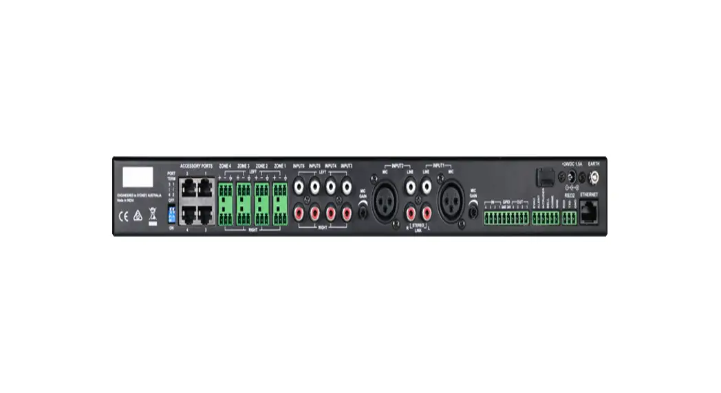
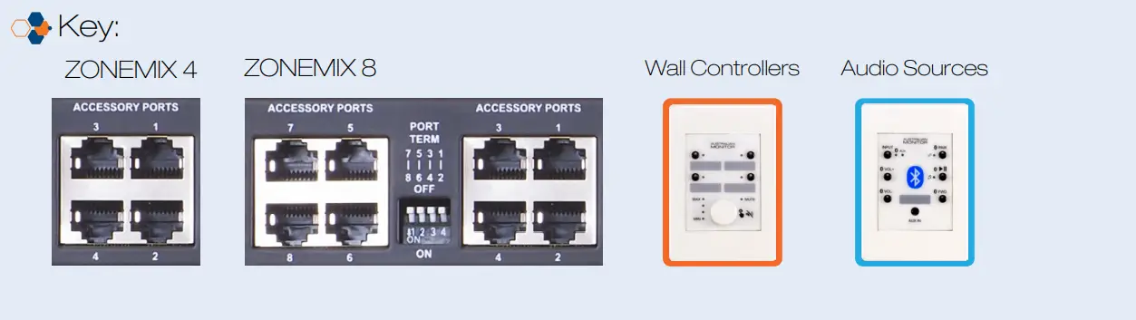
The ZONE MIX accessory ports allow for the connection of wall panels, paging stations and audio input sources. Please follow the guide below to set up your system.

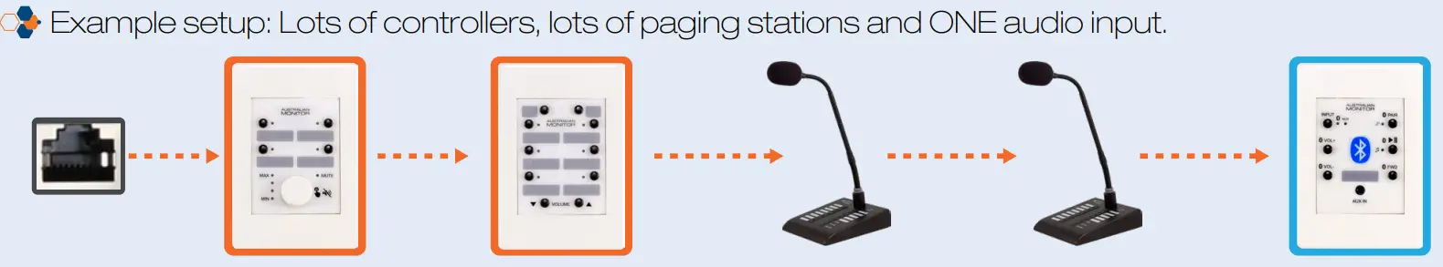
![]() Please note that accessory port local audio input channels are locked to the corresponding output zone and only one can be used per zone. E.g. Accessory port 1 local input connects to Zone 1. However, multiple wall panels and paging stations can be connected on the same accessory port.
Please note that accessory port local audio input channels are locked to the corresponding output zone and only one can be used per zone. E.g. Accessory port 1 local input connects to Zone 1. However, multiple wall panels and paging stations can be connected on the same accessory port.
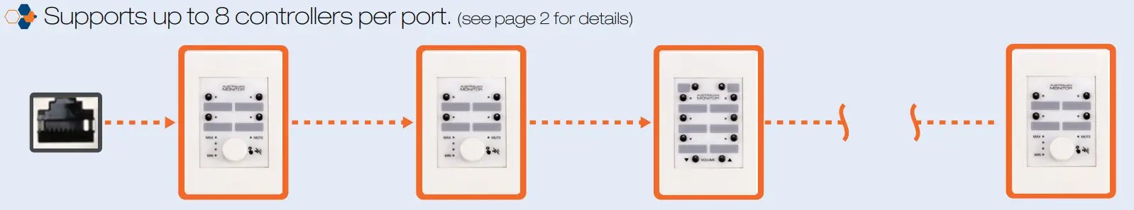
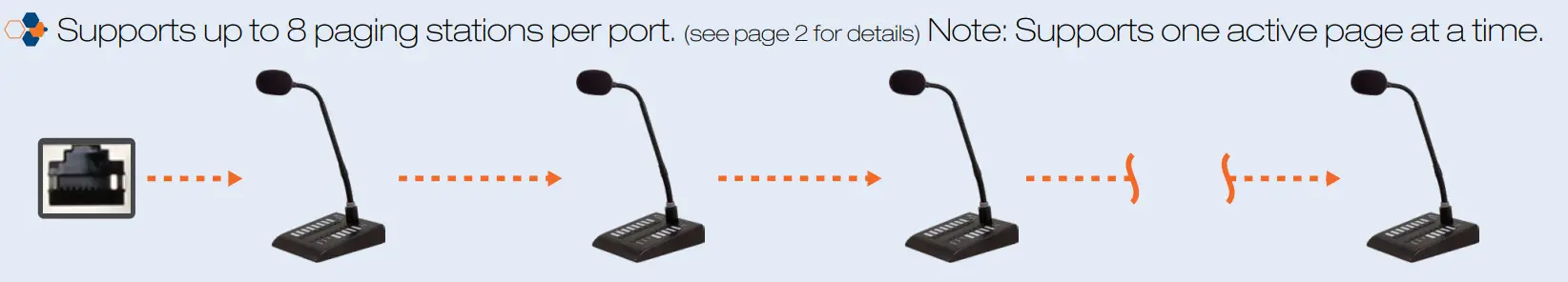
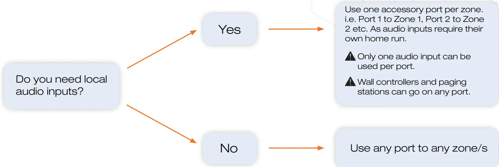
STEP 1: DECIDE PORT WIRING LAYOUT
STEP 2: CONFIRM YOU DO NOT EXCEED THE FOLLOWING LIMITS
| Maximum cable length per port | Accessories per port | Maximum Accessories in the system |
| 100m | 8 | 24 |
| 130m | 7 | |
| 180m | 6 | |
| 250m | 5 | |
| 400m | 4 | |
| 500m | 3 |
The maximum distances quoted in the table are due to DC’s current limitations.
The paging stations and wall panels can be locally powered to increase the cable length to a maximum of 500m. Please read the following additional document: Advanced accessory port wiring guide.
STEP 3: ACCESSORY PORT WIRING
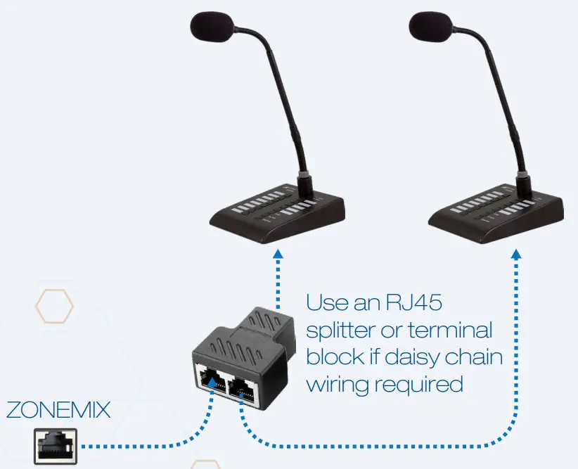
Wire the ZONE MIX and ZMPS paging stations as per the images below.
- Category 5, 5e, and 6 cablings supported.
- T-568A wiring is recommended. However, T-568B is also supported.
ZONEMIX AND ZMPS WIRING
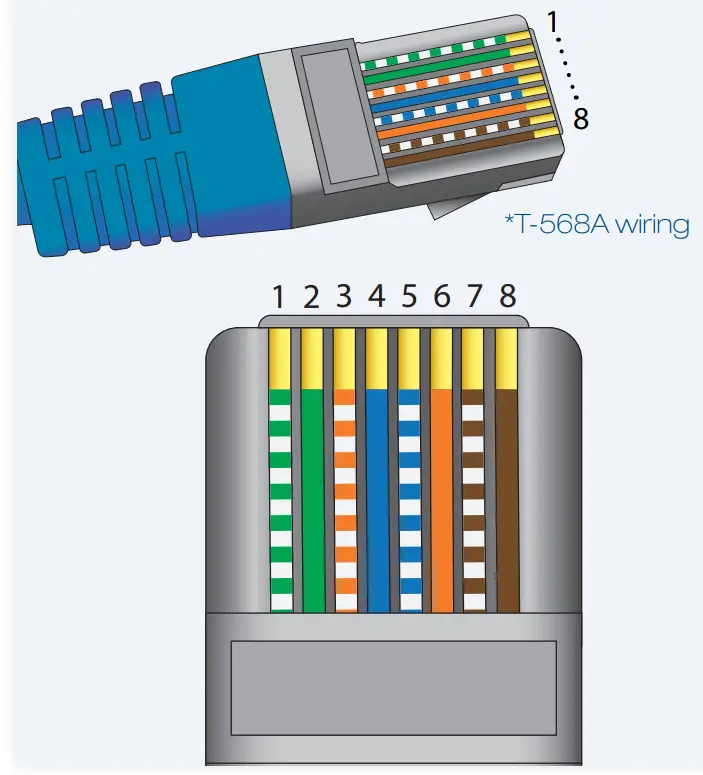
| Pin | Colour | Signal |
| 1 | Green/White | Paging Audio + |
| 2 | Green | Paging Audio – |
| 3 | Orange/White | RS485 B |
| 4 | Blue | +24V DC |
| 5 | Blue/White | GND |
| 6 | Orange | RS485 A |
| 7 | Brown/White | Local Input + |
| 8 | Brown | Local Input – |
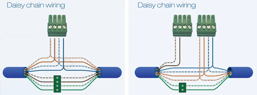
ZMPS DAISY CHAIN WIRING
STEP 3: ACCESSORY PORT WIRING (CONT.)
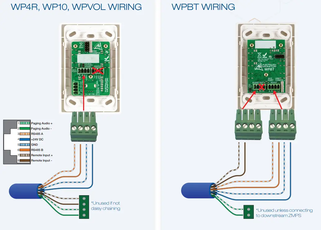
Wire the wall panels as per the images below.
- Category 5, 5e, and 6 cablings supported.
- T-568A wiring is recommended. However, T-568B is also supported.
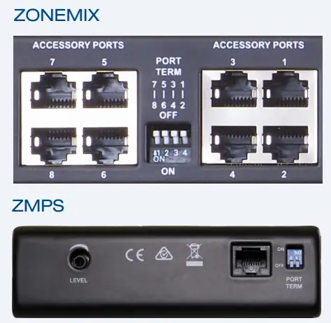
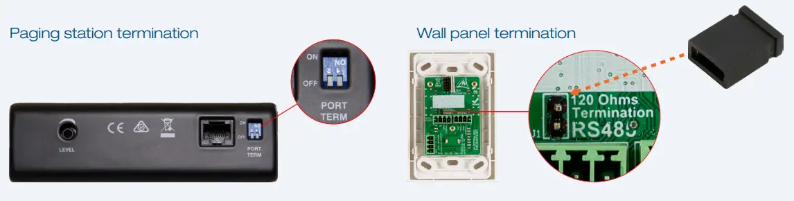
STEP 4: PORT TERMINATION – DO NOT SKIP THIS STEP
The ZONE MIX uses the RS485 standard to communicate to wall panels and paging stations. RS485 requires that each end of the cable run is terminated to prevent signal corruption due to signal reflections in the cable.
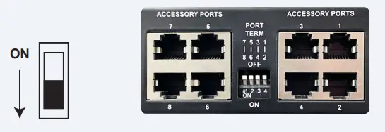
The Accessory Ports are grouped in Pairs. 1+2, 3+4, 5+6, 7+8. You must terminate the ZONE MIX and Accessories based on which ports you use.
- Terminate the ZONE MIX accessory ports, as per the table, using the PORT TERM switches
ACCESSORY PORT TERMINAL SWITCH SETTING ONE PORT USED TERM BOTH PORTS USED TERM Port 1 OR Port 2 used ON Port 1 AND Port 2 used OFF Port 3 OR Port 4 used ON Port 3 AND Port 4 used OFF Port 5 OR Port 6 used ON Port 5 AND Port 6 used OFF Port 7 OR Port 8 used ON Port 7 AND Port 8 used OFF 
- Terminate the LAST RS485 accessory on the port cable run. Paging station termination
 Examples:
 Examples:
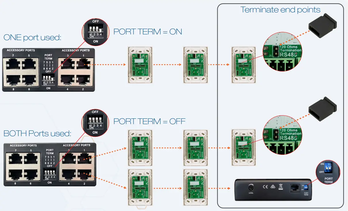
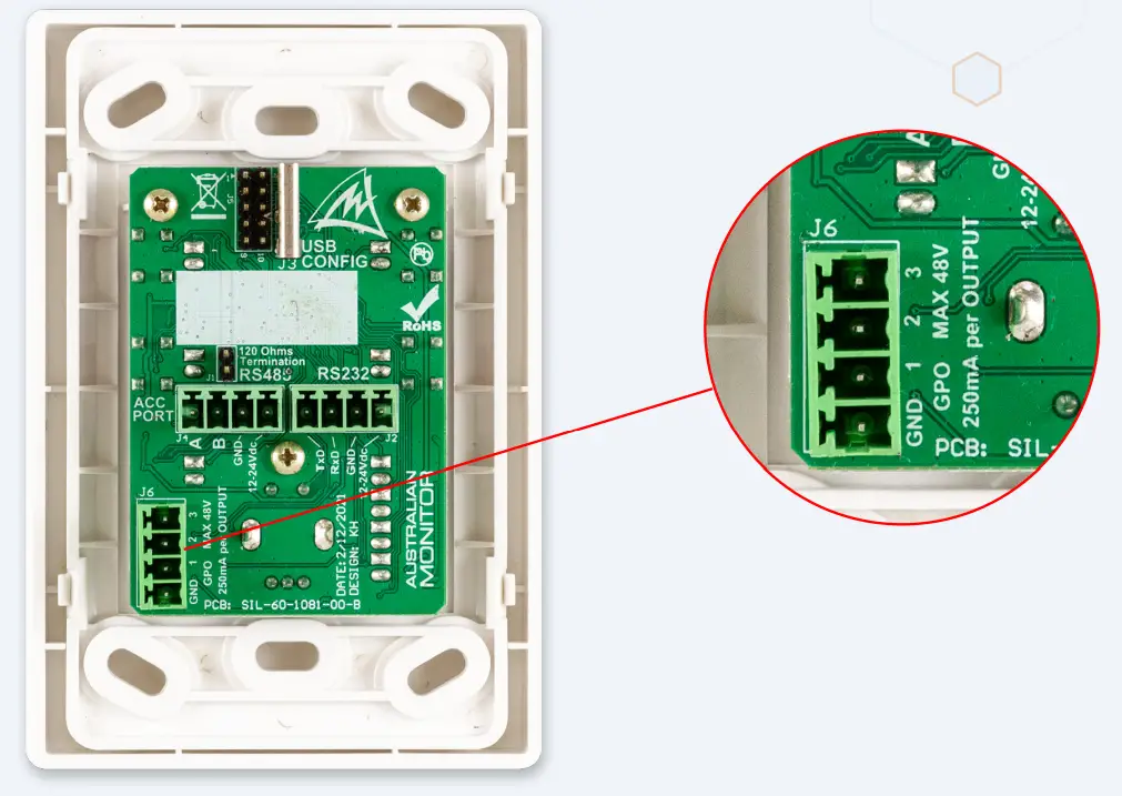
STEP 5: WP4R, WP10 GPO WIRING (OPTIONAL)
The WP4R and WP10 both have 3 general purpose outputs which can be controlled from the wall panel buttons to trigger external devices such as projectors.
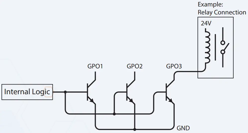
GPO Schematic
Each Output is an open collector transistor. Maximum Voltage: 48V Maximum Sink Current: 250mA
![]()


 230 V User Manual")

 230 V User Guide")


 24v User Manual")
