ROckFLEET Rock7 Wiring Configuration
There are two variations of the RockFLEET wiring configuration with different colours for Power and Ground/Earth. The RockFLEET can also be wired to up to three switches which can be mapped to events such as OPS NORMAL or DISTRESS. Contact TracPlus support to set up the correct mappings for these switches.
New Version – RockFLEET GSM
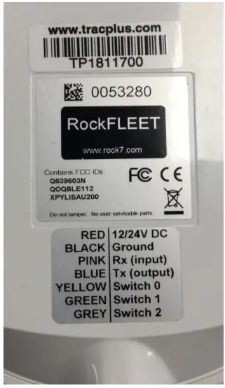
| Wire Colour | Purpose | Details | |
| Red | Power | 12/24V DC | |
| Black | Neutral (Negative) | Ground/Earth | |
| Blue | RS232 | Do not use | |
| Pink | RS232 | Do not use | |
| Yellow | Switch 0 | Activated by taking to ground or from ground | |
| Green | Switch 1 | Activated by taking to ground or from ground | |
| Grey | Switch 2 | Activated by taking to ground or from ground |
Switches
- Power sources must have 2A circuit breakers.
- Switch and sensor inputs are not internally debounced. Input switches or sensors should be externally debounced and must switch between the open circuit and Signal Ground.
- A switch is activated on a change on the switch wire, this can be either going from Low (ground) to High or High to Low (ground).
WARNING: NO VOLTAGE IS TO BE APPLIED TO SWITCH AND SENSOR INPUTS. APPLYING VOLTAGE TO SWITCH AND SENSOR INPUTS WILL RESULT IN DEVICE FAILURE AND VOID YOUR WARRANTY. - Installation must be performed by an appropriately licensed engineer with reference to the requirements of all applicable installation regulations, instructions and guidelines.
The RockFLEET unit is designed to be attached to mains power for most of the time, via the cable. However, it does have an internal rechargeable battery for when the unit loses power.
To attach the unit to mains power, simply wire the positive (brown) and negative (white) cores of the cable into your power supply. The unit will run on any voltage between 9v and 32v. It will draw a maximum of about 700mA under normal operation. If you intend to fuse the circuit Rock7 suggests fitting a 2A fuse.
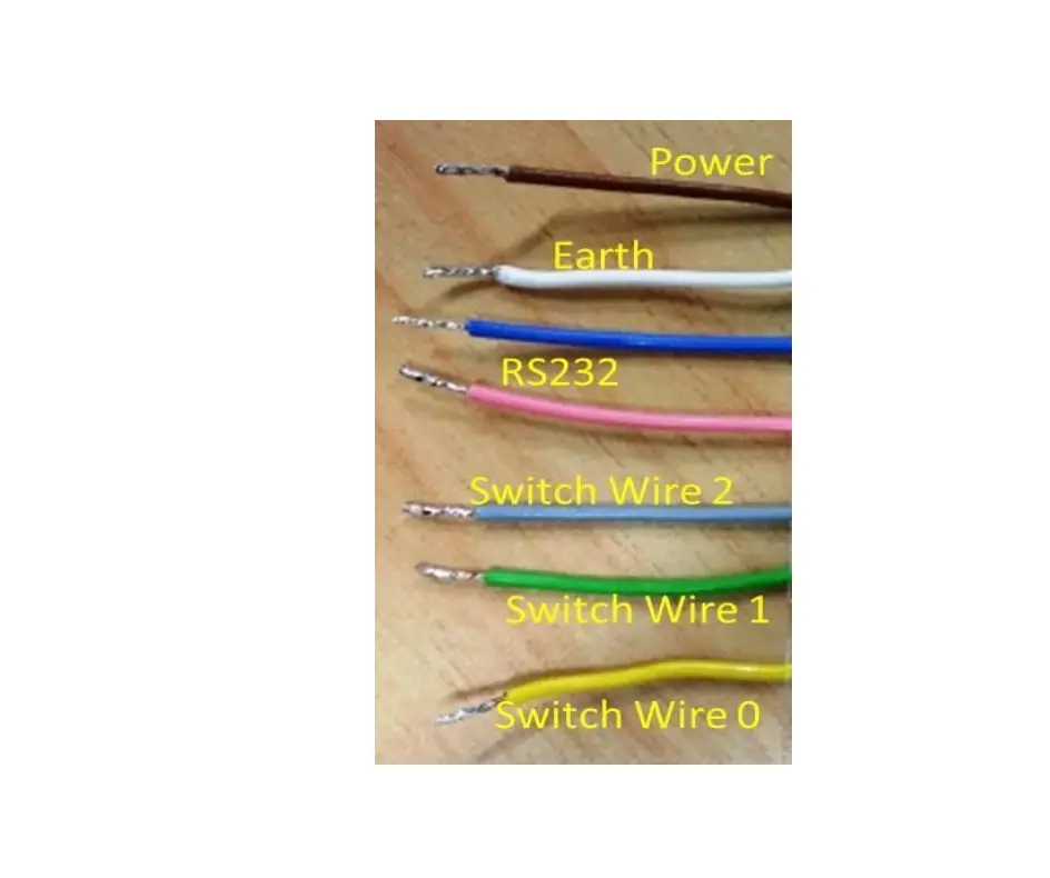
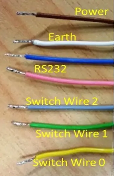
| Wire Colour | Purpose | Details | |
| Brown | Power | 9 to 32 volts | |
| White | Neutral (Negative) | Ground/Earth | |
| Blue | RS232 | Do not use | |
| Pink | RS232 | Do not use | |
| Grey | Switch 2 | Activated by taking to ground or from ground | |
| Green | Switch 1 | Activated by taking to ground or from ground | |
| Yellow | Switch 0 | Activated by taking to ground or from ground | |
| Black | Ground / Screen | Cable Shield, see note below |
Note: The unconnected ground (Black) is a shielded cable – it is designed to only be connected inside the tracker, and is not exposed at the other end of the cable – connecting it both ends would defeat the point of a shield, it is all correctly wired within the device.


