![]()
Catalog Data Effective July 2022
CA650008EN Supersedes November 2020
COOPER POWER
SERIES
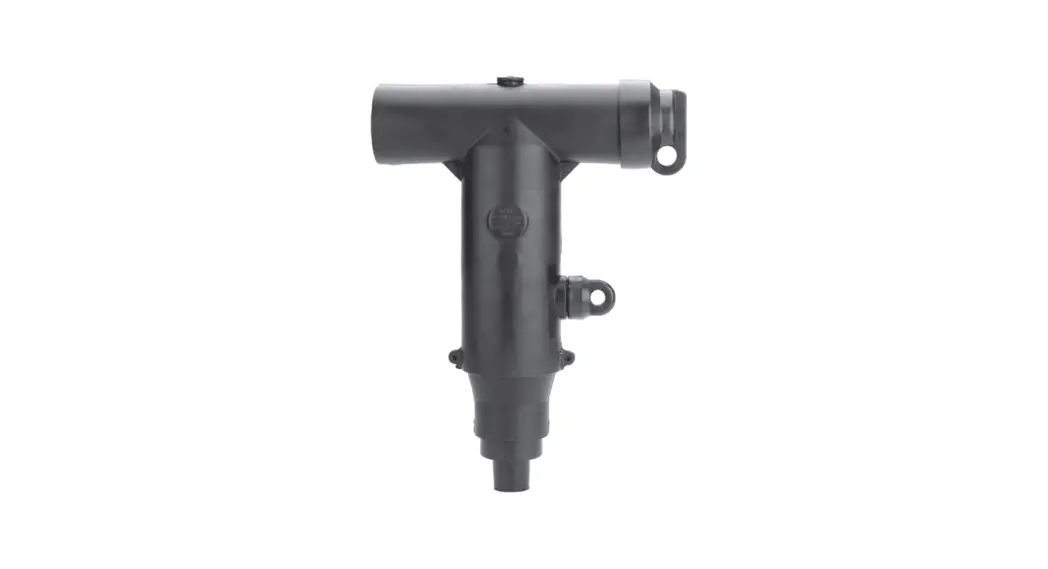
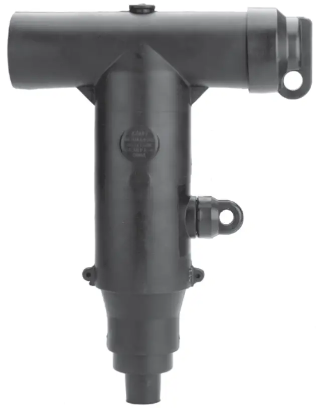 600 A 35 kV Class BOL-T
deadbreak connector
General
Eaton terminates high-voltage underground cables to dead front apparatus such as transformers, switches, and switchgear with its Cooper PowerE series 600 A, 35 kV Class BOL-TE dead break connector. It is fully shielded and submersible and meets the requirements of IEEET Std 386E-2016—“Separable Insulated Connector Systems.” The capacitive test point on the insulating plug provides a means of testing the circuit without disturbing the bolted connection. In addition to the capacitive test point feature on the insulating plug, Eaton offers an optional capacitive test point similar to the test points on its Cooper Power series 200 A elbows. This allows the use of the Type “TPR” faulted circuit indicators, and provides a hot stick operable means of de ter min ing circuit condition when used with high-impedance voltage sensing devices designed for test points. BOL-T connectors are designed for use on solid dielectric cable (XLPE or EPR) with extruded semiconductive shields and concentric neutral, with or without a jacket. Installation on the jacketed concentric neutral cable may require additional sealing material. A special grounding adapter is available for tape shield, linear corrugated, unishield, and drain wire cables for use with dead break connectors.
900 A rating
The BOL-T connector is rated for 900 A continuous when used with a coppertop compression connector or shear bolt, copper insulating plug, copper stud, and copper bushing or junction. If a 900 A rating is desired, specify a “C” as the 9th digit when determining the part number. See Step 3 on page 5.
200 kV BIL rating
The BOL-T connector is available with an optional 200 kV BIL rating, allowing you to match the BIL rating of the system and the equipment to which it will be connected. If 200 kV BIL rating is required, specify “38” in digits 4 and 5 in the part number. See Step 1 on page 4.
Interchangeability
Eaton’s Cooper Power series 600 A dead break connectors conform to the electrical, mechanical, and dimensional requirements of IEEE Std 386-2016. The connectors can be used on any comparably rated bushing interface that also meets the requirements of this standard. In addition, all cable adapters, insulating plugs, and compression connectors are designed to be interchangeable with those currently available from other major manufacturers that also certify their components to IEEE Std 386-2016.
Installation
A torque wrench and 1-inch socket are used to tighten the insulating plug through the com pres sion or shear bolt connector within the T-body onto a de-energized 600 A bushing interface. Refer to Service Information MN650002EN 600 A 35 kV Class BOL-T Connector Assembly Installation Instructions for details.
Production tests
Tests are conducted in accordance with IEEE Std 386-2016:
- ac 60 Hz 1-minute withstand
- 50 kV/70 kV
- Minimum partial discharge extinction voltage
- 26 kV
Tests are conducted in accordance with Eaton requirements: - Physical inspection
- Periodic dissection
- Periodic X-ray analysis
Table 1. Voltage ratings and characteristics
| Description | kV |
| Standard voltage class | 35 |
| Maximum rating phase-to-ground | 21.1 |
| ac 60 Hz 1-minute withstand 150 kV BIL class BOLT 200 kV BIL class BOLT | 50 70 |
| dc 15-minute withstand | 103 |
| BIL and full wave crest | 150/200 |
| Minimum partial discharge extinction voltage | 26 |
Note: N Voltage ratings and characteristics meet or exceed IEEE Std 386-2016.
Table 2. Current ratings and characteristics
| Description | Amperes |
| Continuous | 600 A rms (aluminum) 900 A RMS (copper or shear bolt) |
| 4-hour overload | 900 A rms (aluminum) 1200 A rms (copper or shear bolt) |
| Short time (aluminum) | 25,000 A rms symmetrical for 0.20 s |
| 10,000 A rms symmetrical for 4 s | |
| Short time (copper or shear bolt) | 40,000 A rms symmetrical for 0.17 s |
| 27,000 A rms symmetrical for 4 s |
Features and benefits
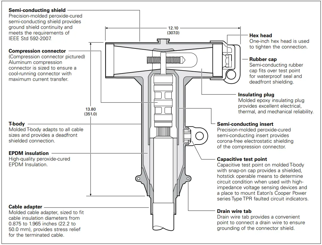
Figure 1. BOL-T cutaway design features
Note: Dimensions are in inches (mm) and are for reference only.
Optional features
Coppertop compression connectors
Coppertop compression connectors (aluminum sleeve welded to a copper spade) provide a high-conductivity material in a bolted connection and are compatible with aluminum or copper conductors.
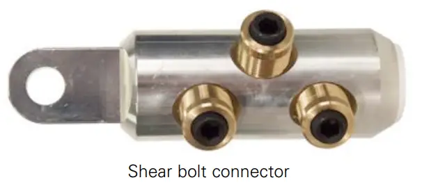
Shear bolt connectors
Bolted cable lug is fitted with stepless bolts, which shear off when optimum contact force has been reached. Provide electrical continuity for copper and aluminum conductors while eliminating the need for dies and compression tools.
All copper current path
The full copper current-carrying path can be obtained by specifying a coppertop compression connector, copper stud, and copper insulating plug.
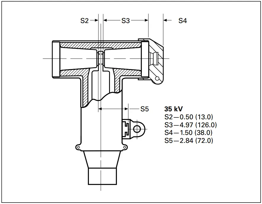
Figure 2. BOL-T stacking dimensions in inches (mm)
Ordering information
Each BOL-T connector kit contains:
- Molded rubber T-body
- Insulating plug
- Cap
- Compression or shear bolt connector
- Cable adapter
- Silicone lubricant
- Installation instruction sheet
To order a 35 kV class BOL-T connector kit, see Steps 1–5 to build the catalog number.
BOL-T connector kit—catalog numbering system
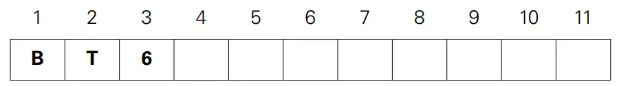
Build the 12-digit catalog number for a BOL-T kit by following the steps given below. The first 5 digits are “BT625”, so only digits 6 through 12 need to be selected.
Catalog number digits:
1 and 2 — “BT” = BOL-T connector system
3 — “6” = 600 A system
Step 1. Select digits 4 and 5 BIL rating requirement
“35” = 35 kV class bushing interface, 150 kV BIL
“38” = 35 kV class bushing interface, 200 kV BIL
Step 2. Select digit 6 cable adapter range code
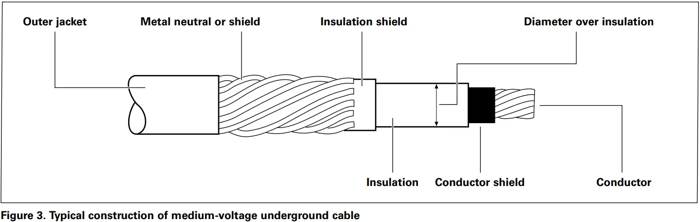
Determine the cable’s diameter over the electrical insulation as shown in Figure 3 (including tolerances).
Then identify a cable range from Table 3 that covers the minimum and maximum insulation diameters. Select the correct cable adapter range code from Table 3.
Table 3. Cable diameter range
| Inches | mm | Cable adapter range code |
| 0.875–0.985 | 22.2–25.0 | D |
| 0.930–1.040 | 23.6–26.4 | E |
| 0.980–1.115 | 24.9–28.3 | F |
| 1.040 –1.175 | 26.4–29.8 | G |
| 1.095 –1.240 | 2 7.8 – 31.5 | H |
| 1.160 –1.305 | 29.5–33.1 | J |
| 1.220 –1.375 | 31.0–34.9 | K |
| 1.285 –1.395 | 32.5–35.4 | L |
| 1.355 –1.520 | 34.4–38.6 | M |
| 1.485 –1.595 | 3 7.7– 4 0.5 | N |
| 1.530 –1.640 | 38.9 – 41.7 | P |
| 1.575 –1.685 | 40.0–42.8 | Q |
| 1.665 –1.785 | 42.3–45.3 | R |
| 1.755 –1.875 | 4 4.6 – 47.9 | S |
| 1.845 –1.965 | 46.9–50.0 | T |
| 1.960 –2.210 | 49.8–56.1 | U |
Step 3. Select digits 7 and 8 conductor code
Identify the conductor size and type in Table 4 (compression) or Table 5 (shear bolt) and select the conductor code from the appropriate column.
Table 4. Compression connector
Concentric or compressed Compact or solid
| AWG or k | mm2 | AWG or kcmil | mm2 | Conductor code |
| No connec | 0 | |||
| #2 | 35 | 1 | — | 11 |
| #1 | — | Jan-00 | 50 | 12 |
| Jan-00 | 50 | Feb-00 | 70 | 13 |
| Feb-00 | 70 | Mar-00 | — | 14 |
| Mar-00 | — | Apr-00 | 95 | 15 |
| Apr-00 | 95 | 250 | 120 | 16 |
| 250 | 120 | 300 | — | 17 |
| 300 | — | 350 | — | 18 |
| 350 | — | 400 | 185 | 19 |
| 400 | 185 | 450 | — | 20 |
| 450 | — | 500 | 240 | 21 |
| 500 | 240 | 600 | 300 | 22 |
| 600 | 300 | 700 | — | 23 |
| 650 | — | 750 | — | 24 |
| 750 | — | 900 | — | 25 |
| 900 | — | 1000 | 500 | 26 |
| 1000 | 500 | — | — | 27 |
| 1250 | 630 | 1250 | — | 28 |
Table 5. Shear bolt connector
Cable conductor size
AWG or kcmil
| Compact | Compressed | Concentric | mm2 standard sizes | Conductor code | Catalog number |
| 1/0 | 1/0 | 1/0 | 50 | S1 | CDT630SB150 |
| 2/0 | 2/0 | 2/0 | 70 | ||
| 3/0 | 3/0 | 3/0 | — | ||
| 4/0 | 4/0 | 4/0 | 95 | ||
| 250 | 250 | 250 | 120 | ||
| 350 | — | — | 150 | ||
| — | Dec-00 | 350 | 185 | S3 | CDT630SB300 |
| 500 | May-01 | 500 | 240 | ||
| 600 | Aug-01 | 600 | 300 | ||
| 700 | — | — | — | ||
| — | 700 | 700 | — | S4 | CDT630SB400 |
| 750 | 750 | 750 | — | ||
| 800 | 800 | — | 400 | ||
| 900 | — | — | — | ||
| — | — | 800 | — | S6 | CDT1250SB630 |
| — | 900 | 900 | — | ||
| 1000 | 1000 | 1000 | 500 | ||
| — | 1100 | 1100 | — | ||
| — | 1200 | 1200 | — | ||
| — | 1250 | 1250 | 630 | ||
| — | 1300 | 1300 | — | S8 | CDT1250SB800 |
| — | 1400 | 1400 | — | ||
| — | 1500 | 1500 | 800 |
Step 4. Select digit 9
Determine whether aluminum or copper is required for the compression connector, stud, and dead break insulating plug.
“A” = Aluminum (shear bolt or compression connector)
“C” = Copper mating components (shear bolt or coppertop for the connector) required to achieve a 900 A rating
Step 5. Select digit 10
Determine if a stud should be included in the kit. The stud will be fixed inside the dead break insulating plug.
“1” = Stud included
“2” = Stud not included
Step 6. Select digit 11
Determine if the T-body should have a test point.
“T” = Test point on T-body If no test point is required, do not include the 11th digit.
Example
Select a 200 kV BIL BOL-T kit for 250 kcal compressed cable with a nominal insulation diameter of 1.16 inches. The kit should have aluminum current-carrying parts and should have a stud included. The T-body should have a test point.
Step 1. Select digits 4 and 5
This kit requires a 200 kV BIL interface.
Select “38” for digits 4 and 5.
Step 2. Select digit 6
Nominal diameter over insulation is 1.16 ± 0.030 inches.
Minimum diameter = 1.16 – 0.030 = 1.13 inches.
Maximum diameter = 1.16 + 0.030 = 1.19 inches.
From Table 3, identify the cable range that covers 1.13–1.19 inches and select the “H” cable range code.
Step 3. Select digits 7 and 8
The conductor size is 250 kcal compressed. From Table 4, under the column “Concentric or compressed,” identify 250 kcmil and select the “17” conductor code.
Step 4. Select digit 9
This kit requires aluminum current-carrying parts. Select an “A” for digit 9.
Step 5. Select digit 10
This kit requires a stud. Select “1” for digit 10.
Step 6. Select digit 11
A test point is needed. Use “T” for digit 11.
The complete catalog number is: BT638H17A1T.
Accessories
Cable adapters, compression connectors, and other accessories that can be used with BOL-T connectors are described in Catalog Data CA650006EN, “Deadbreak accessories, tools, and replacement parts.”
Table 6. Replacement parts
| Description | Catalog number |
| T-body without test point | DT625 |
| T-body with test point | DT625T |
| T-body without test point with aluminum stud | DT625SA |
| T-body without test point with copper stud | DT625SC |
| T-body with test point with aluminum stud | DT625TSA |
| T-body with test point with copper stud | DT625TSC |
| Insulating plug cap | DIPCAP |
| Aluminum insulating plug with cap (no stud) | DIP625A |
| Copper insulating plug with cap (no stud) | DIP625C |
| Aluminum insulating plug with cap and aluminum stud | DIP625AS |
| Copper insulating plug with cap and copper stud | DIP625CS |
| 5/8-inch – 11 UNC 2 A aluminum threaded stud | STUD-A |
| 5/8-inch – 11 UNC 2 A copper threaded stud | STUD-C |
| Eaton 1000 Eaton Boulevard Cleveland, OH 44122 United States Eaton.com | Eaton’s Power Systems Division 2300 Badger Drive Waukesha, WI 53188 United States Eaton.com/cooperpowerseries | © 2022 Eaton All Rights Reserved Printed in USA Publication No. CA650008EN / Z26565 July 2022 |
![]()
Eaton is a registered trademark.
All other trademarks are property
of their respective owners.


