![]() COOPER POWER SERIES 600 A 15 kV Class T-OP II
COOPER POWER SERIES 600 A 15 kV Class T-OP II
deadbreak connector
Instruction Manual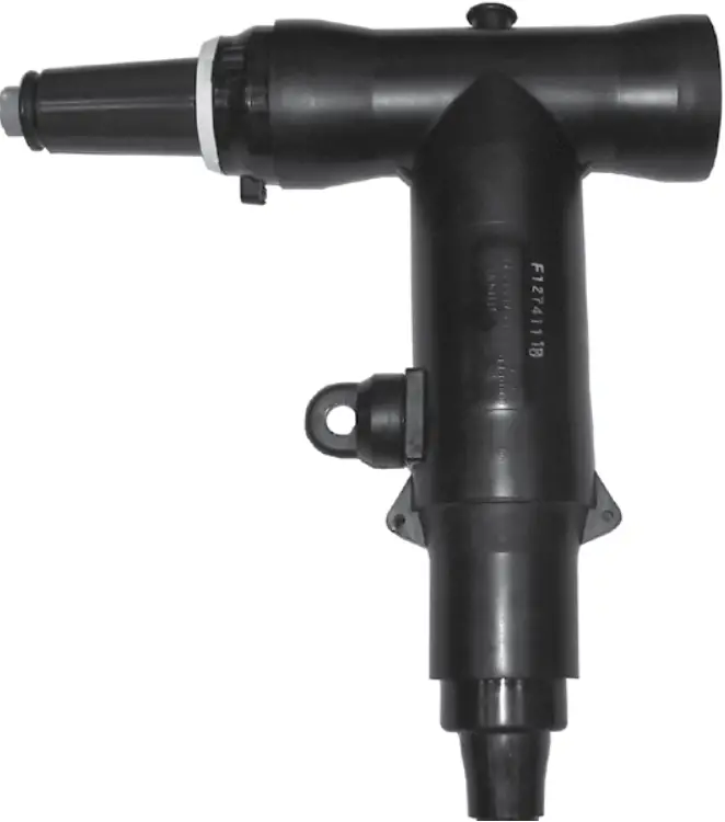
General
Eaton terminates high-voltage underground cable to transformers, switches, switchgear, and other apparatus with its Cooper PowerE series 600 A, 15 kV Class T-OPE II deadbreak connector. It is fully shielded and submersible and meets the requirements of IEEET Std 386E-2016— “Separable Insulated Connector Systems.” The 200 A three-phase rated load break interface provides a means for obtaining a live test, visible ground, and visible break using a hot stick. It also provides a convenient location for Eaton’s Cooper Power series metal oxide varistor elbow (M.O.V.E.) arrester or grounding elbow. Eaton offers an optional capacitive test point similar to its Cooper Power series 200 A elbow connectors. This allows use of Eaton’s Cooper Power series STLO, STHI, and STVT faulted circuit indicators. T-OP II connectors are designed for use on solid dielectric cable (XLPE or EPR) with extruded semi-conducting shields and concentric neutral, with or without a jacket. Installation on the jacketed concentric neutral cable may require additional sealing material. Adapters are available for terminating tape shields and drain wire jacketed cable.
900 A rating
The T-OP II connector is rated for 900 A continuous when used with a copper bushing or junction.
Interchangeability
All Eaton’s Cooper Power series 600 A deadbreak connectors conform to the electrical, mechanical, and dimensional requirements of IEEE Std 386-2016. The connectors can be used on any comparably rated bushing interface that also meets the requirements of this standard. In addition, all T-bodies, cable adapters, insulating plugs, and compression connectors are designed to be interchangeable with those currently available from other major manufacturers that also certify their components to IEEE Std 386-2016.
Installation
The T-body is assembled onto prepared cable with a threaded coppertop compression connector or shear bolt using the alignment segment and a T-wrench. The short end of a special copper alloy stud, provided with the kit, is torqued onto a de-energized 600 A bushing. The assembled housing is then connected to the apparatus bushing using an O & T tool (with cap) and an installation torque tool.
The T-OP ll connector’s unique back-off feature is accomplished by a captured rotating nut, which provides ease of removal of the T-OP II connector system from the apparatus bushing. (See Table 6 for information on tools.) Refer to Installation Instruction Sheet MN650048EN for details.
Production tests
Tests are conducted in accordance with IEEE Std 386-2016:
- ac 60 Hz 1-minute withstand
- 34 kV
- Minimum partial discharge extinction voltage
- 11 kV
Tests are conducted in accordance with Eaton re quire ments:
- Physical inspection
- Periodic dissection
- Periodic fluoroscopic analysis
Table 1. Voltage ratings and characteristics
| Description | kV |
| Standard voltage class | 15 |
| Maximum rating phase-to-phase (loadbreak-reducing tap plug only) | 14.4 |
| Maximum rating phase-to-ground | 8.3 |
| ac 60 Hz 1-minute withstand | 34 |
| dc 15-minute withstand | 53 |
| BIL and full wave crest | 95 |
| Minimum partial discharge extinction voltage | 11 |
Note: Voltage ratings and characteristics are in accordance with IEEE Std 386-2016.
Table 2. Current ratings and characteristics
| Description | Amperes |
| 600 A Interface | |
| Continuous | 600 A rms (aluminum) 900 A rms (copper) |
| 4-hour overload | 900 A rms (aluminum) 1200 A rms (copper) |
| Short time | 25,000 A rms symmetrical for 0.20 s |
| 10,000 A rms symmetrical for 4 s | |
| 200 A Interface a | |
| Continuous | 200 A rms |
| Switching | 10 operations at 200 rms at 14.4 kV phase-to-phase |
| Fault closure | 10,000 A rms symmetrical at 14.4 kV phase-to-phase after 10 switching operations for 0.17 s |
| Short time | 10,000 A rms symmetrical for 0.17 s |
| 3500 A rms symmetrical for 3 s | |
1 System design and protection must recognize the ratings of 200 A interface.
Note: Current ratings and characteristics are in ac cor dance with IEEE Std 386-2016.
Features and benefits

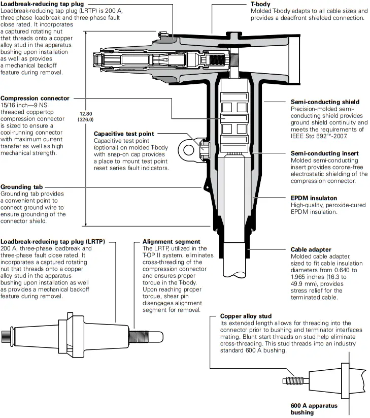
Figure 1. Cutaway design features
Note: Dimensions are in inches (mm) and are for reference only.
Optional features
Protective cap
200 A insulated protective cap fits over a loadbreak-reducing tap plug for deadfront shielding.
Capacitive test point
Capacitive test point on molded T-body, with snap-on cap, provides a place to mount STLO, STHI, and STVT faulted circuit indicators.
Copper alloy stud
The copper alloy stud with its extended length allows for threading into the connector prior to mating the bushing and terminator interfaces. Blunt start threads on the stud help eliminate cross threading. Stud threads into an industry-standard 600 Abushing.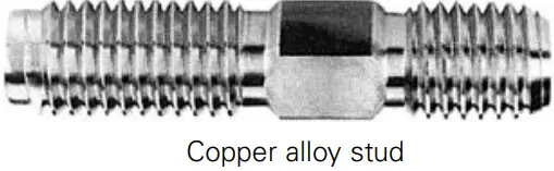 T-wrench
The T-wrench is used to install the loadbreak-reducing tap plug into the compression connector and T-body.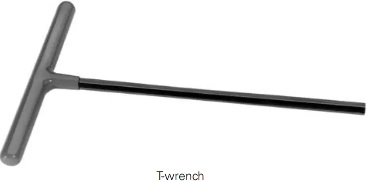 Torque tool
The torque tool is required to check the torque of a 15 kV Class T-OP II deadbreak connector or bushing adapter when it is installed on a 600 A bushing interface. It is precision calibrated and hotstick operable.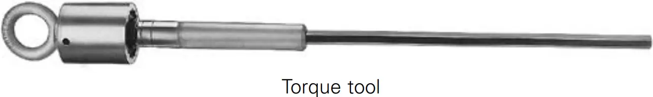
Combination operating and test/torque tool
The combination operating and test/torque tool is used with a hot stick to test for circuit de-energization and to install and remove a 15 kV Class LRTP equipped connector from an apparatus tap. The standard tool is equipped with a molded EPDM rubber cap and torque limiter to allow proper tool seating and gripping of the T-OP II connector. It also ensures that the connector has been properly torqued into the mating bushing.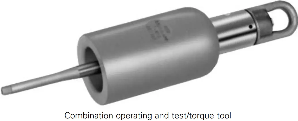 5/16-inch hex shaft
5/16-inch hex shaft with 3/8-inch socket drive tool.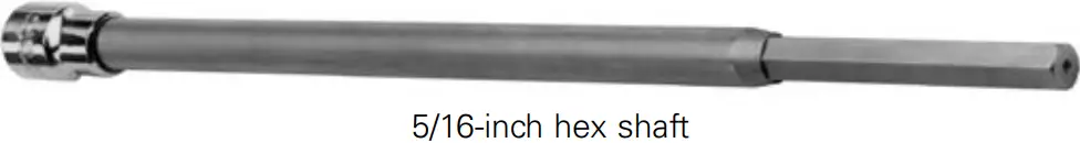
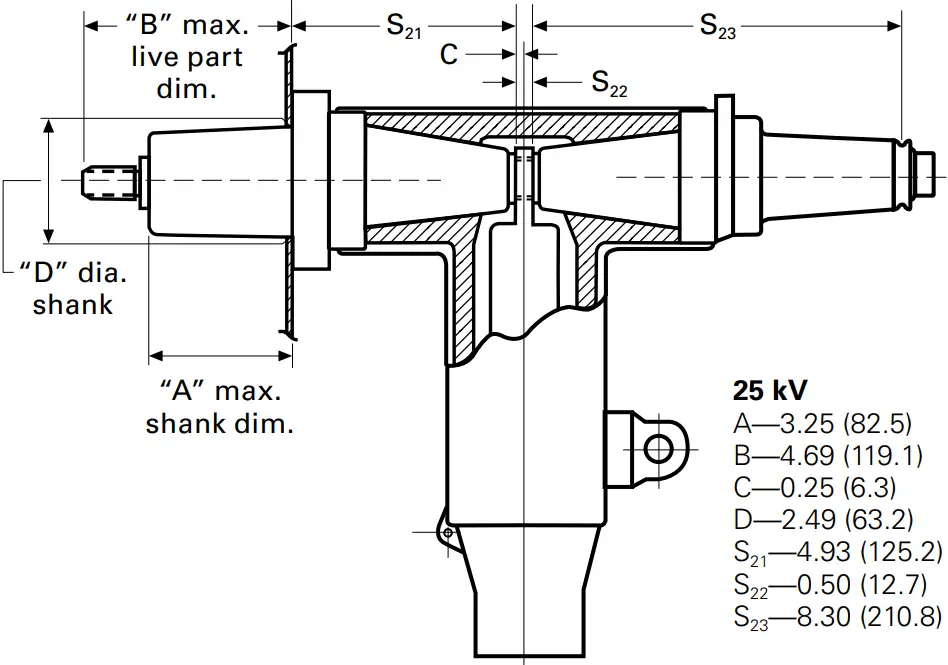 Figure 2. T-OP II profile and stacking dimensions in inches (mm)
Ordering information
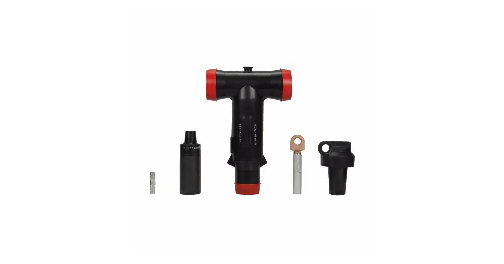
Each T-OP II connector kit contains:
- Molded rubber T-body
- Loadbreak-reducing tap plug
- Cable adapter
- Coppertop compression connector
- Copper alloy stud
- Silicone lubricant
- Installation instruction sheet
Catalog number selection
Use the following procedure to develop the correct part number for the desired T-OP II connector kit, based on cable size, conductor size, and desired options.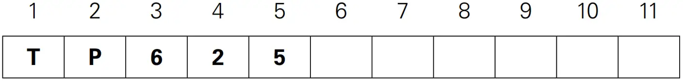 Catalog number digits:
1 and 2 — “TP” = T-OP connector system
3 — “6” = 600 A system
4 and 5 — “15” = 15 kV
Step 1. Select digits 6 and 7 cable range code
Determine the cable’s diameter over the electrical insulation as shown in Figure 3 (including tolerances). Then identify a cable range from Table 3 that brackets the minimum and maximum insulation diameters. Select the correct cable range code.
Table 3. Cable diameter range
| Inches | mm | Cable range code |
| 0.61–0.97 | 15.5–24.6 | AB |
| 0.75–1.08 | 19.1–2 7.4 | CC |
| 0.97–1.31 | 24.6–33.3 | DD |
| 1.09 –1.47 | 2 7.7– 3 7.3 | EE |
| 1.26–1.64 | 32.0 – 41.7 | FF |
| 1.36–1.71 | 34.5–43.4 | GG |
| 1.51–1.85 | 3 8.4 – 47.0 | HH |
| 1.70 –1.97 | 43.2–50.0 | JJ |
Step 2. Select digits 8 and 9 conductor code
Identify the conductor size and type in Table 4 (compression) or Table 5 (shear bolt) and select the conductor code from the appropriate column.
Table 4. Compression connector
| Concentric or compressed | Compact or solid | |||
| AWG or kcmil | mm² | AWG or kcmil | mm² | Conductor code |
| No connector | 0 | |||
| #2 | 35 | 1 | — | 11 |
| #1 | — | Jan-00 | 50 | 12 |
| Jan-00 | 50 | Feb-00 | 70 | 13 |
| Feb-00 | 70 | Mar-00 | — | 14 |
| Mar-00 | — | Apr-00 | 95 | 15 |
| Apr-00 | 95 | 250 | 120 | 16 |
| 250 | 120 | 300 | — | 17 |
| 300 | — | 350 | — | 18 |
| 350 | — | 400 | 185 | 19 |
| 400 | 185 | 450 | — | 20 |
| 450 | — | 500 | 240 | 21 |
| 500 | 240 | 600 | 300 | 22 |
| 600 | 300 | 700 | — | 23 |
| 650 | — | 750 | — | 24 |
| 750 | — | 900 | — | 25 |
| 900 | — | 1000 | 500 | 26 |
| 1000 | 500 | — | — | 27 |
| 1250 | 630 | 1250 | — | 28 |
Table 5. Shear bolt connector
Cable conductor size
AWG or kcmil
| Compact | Compressed | Concentric | mm² standard sizes | Conductor code | Catalog number |
| Jan-00 | Jan-00 | Jan-00 | 50 | S1 | CDT630SB150T |
| Feb-00 | Feb-00 | Feb-00 | 70 | ||
| Mar-00 | Mar-00 | Mar-00 | — | ||
| Apr-00 | Apr-00 | Apr-00 | 95 | ||
| 250 | 250 | 250 | 120 | ||
| 350 | — | — | 150 | ||
| — | 350 | 350 | 185 | S3 | DT630SB300T |
| 500 | 500 | 500 | 240 | ||
| 600 | 600 | 600 | 300 | ||
| 700 | — | — | — | ||
| — | 700 | 700 | — | S4 | CDT630SB400T |
| 750 | 750 | 750 | — | ||
| 800 | 800 | — | 400 | ||
| 900 | — | — | — | ||
| — | — | 800 | — | S5 | CDT900SB500T |
| — | 900 | 900 | — | ||
| 1000 | 1000 | 1000 | 500 |
Step 3. Select digit 10 and 11 (optional)
“TC” = T-OP II connector kit with a capacitive test point and protective cap
“C” = T-OP II connector kit with a protective cap (no capacitive test point)
Blank = T-OP II connector kit without capacitive test point or protective cap
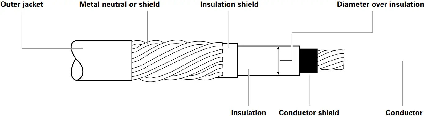
Figure 3. Typical construction of medium-voltage underground cable
Example
Select a T-OP II kit without a capacitive test point with a protective cap for a 4/0 compressed cable with a nominal insulation diameter of 0.920 inch.
Step 1. Select digits 6 and 7
Nominal diameter over the insulation is 0.920 ± 0.030 inch
Minimum diameter = 0.0920 – 0.030 = 0.890 inch
Maximum diameter = 0.920 + 0.030 = 0.950 inch
From Table 3, identify the cable range 0.890 – 0.950 inch and select the “CC” cable range code.
Step 2. Select digits 8 and 9
The conductor size is a 4/0 compressed. From Table 4, under the column “Concentric or compressed,” identify 4/0 and select the “16” conductor code.
Step 3. Select digit 10
The kit should have a protective cap. Select a “C” for digit 10.
Order catalog number: TP615CC16C.
Accessories
To order replacement parts and tools, refer to Table 6.
To order replacement compression connectors and cable adapters for a T-OP II connector system, see Catalog CA650007EN 600 A 15 and 25 kV Deadbreak Accessories, Tools and Replacement Parts.
Table 6. Replacement parts and tools
| Description | Catalog number |
| T-body without test point | DT625 |
| T-body with test point | DT625T |
| Loadbreak-reducing tap plug (LRTP) | LRTP615 |
| Installation torque tool | TQHD625 |
| Operating and test tool | OT625 |
| Combination operating and test/torque tool | OTTQ615 |
| 5/16-inch T-wrench | TWRENCH |
| Copper alloy stud | STUD-T |
| 15 kV, 200 A insulated protective cap | LPC215 |
| 5/16-inch Hex shaft with 3/8-inch socket drive tool | HD625 |
![]() Powering Business Worldwide
Powering Business Worldwide
www.eaton.com
Eaton 1000 Eaton Boulevard Cleveland, OH 44122 United States
Eaton.com
Eaton’s Power Systems Division 2300 Badger Drive Waukesha, WI 53188 United States
Eaton.com/cooperpowerseries
© 2022 Eaton All Rights Reserved Printed in USA
Publication No. CA650017EN / Z26565 July 2022


