![]() MMW-2 Wireless Wall Thermostats
MMW-2 Wireless Wall Thermostats
Instruction Manual Installation Manual
MMW-2
Thermostat Application Guide
| Description | |
| Gas or al Heat | Yes |
| Electric Frnace | Yes |
| Heat pump No Aux. or Emergency Head | Yes |
| Heat Pump IVAth Electric Aux.) | Yes |
| Heat Pump (With Gas Aux.) | No |
| MulthStage Systems | No |
| Heat Only Systems – Floor or Wall Furnace | Yes |
| Cool Only Systems | Yes |
| High and Low Fan Speed | Yes |
| matron | No |
| Emergency Heat | No |
| Conventional Single Stage Furnace | Yes |
| Geothermal | Yes |
Power Type
Battery Power
Hardwire (Common Wire)
Hardwire (Common Wire) with Battery Backup
A trained, experienced technician must install this product.
Carefully read these instructions. You could damage this product or cause a hazardous condition if you fail to follow these instructions.
Installation Tips
Wall Locations
The thermostat should be installed approximately 4 to 5 feet above the floor. Select an area with average temperature and good air circulation.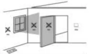
![]() Installation Tips
Installation Tips
Pick on intallation location that is easy for the user to accers. The tempetured of the location should be representative of the buiking.
Do not install thermostat in locations:
- Close to hot or cold air ducts
- That are in direct sunlight
- With an outside wall behind the thermostat
- In areas that do not require conditioning
- Where there are dead spots or drafts (in corners or behind doors)
- Where there might be concealed chimneys or pipes
Subbase Installation
- Horizontal Mount
- vertical Mount
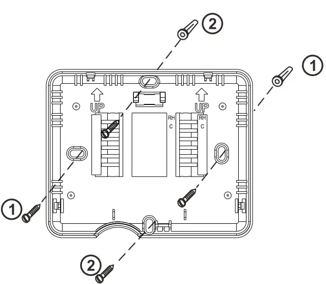
For vertical mount put one scow on the top and one screw on the bottom.
For horizontal mount put one screw on the left and one screw on the right.![]() Installation Tip:
Installation Tip:
Electrical Hazard Failure to disconnect the power before beginning to install this product can cause electrical shock or equipment damage.![]() Mercury Notice
Mercury Notice
All of our products are mercury free. However, if the product you are replacing contains mercury, dispose of it properly.
Your local waste management authority can give you instructions on recycling and proper disposal.
Mount Thermostat
Align the 4 tabs on the subbase with corresponding slots on the back of the thermostat, then push gently until the thermostatsnaps in place.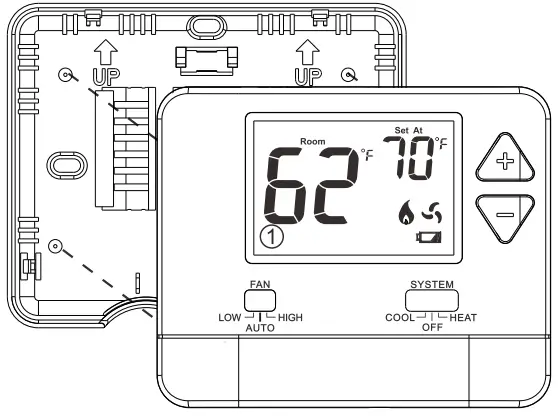 Battery Installation
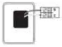 .Battery installation is optional if thermostat is hardwired (R and C terminal connected to 24V power).
Important: High quality alkaline batteries are recommended. Rechargeable batteries or low quality batteries do not guarantee a 1-year life span.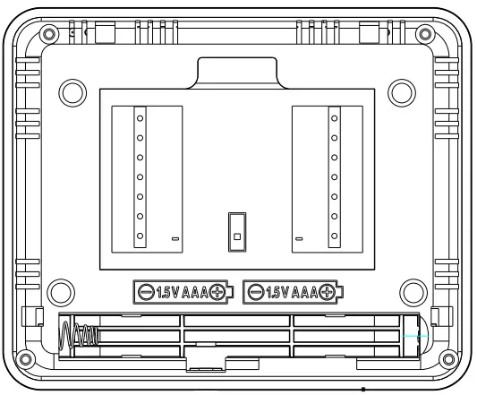 Insert 2 AAA Alkaline batteries (included). High quality alkaline batteries are recommended
Thermostat Quick Reference
Getting to know your thermostat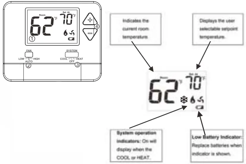
- LCD
- Fan Switch
- System Switch
- Setpoint Buttons
Wiring
- If you are replacing a thermostat, make note of the terminal connections on the thermostat that is being replaced. In some cases the wiring connections will not be color coded. For example, the red wire may not be connected to the R terminal.
- Loosen the terminal block screws. Insert wires then retighten terminal block screws.
![]() Installation Tip
Installation Tip
Do not overtighten terminal block screws, as this can damage the terminal block. A damaged terminal block can keep the thermostat from fitting on the subbase correctly or cause system operation issues.
Max Torque = 6in-Ibs.
| Conventional | Heat Pump | |
| R | Transformer power | Transformer power |
| C | — | Transformer common |
| B | Transformer common | B/O Changergeover value See Tech Set up |
| GL | Fan Relay, Low | Fan Relay, Low |
| GH | Fan Relay, High | Fan Relay, High |
| W | First stage of heat | Second stage of heat |
| Y | First stage of cool | First stage of heat & cool |
Wiring
This thermostat is shipped from the factory to operate a conventional heating and cooling system. This thermostat will also operate a heat pump system. See the “heat pump” configuration step on page 10 of this manual to configure the thermostat for heat pump applications.
Wiring Tips![]() Caution: Electrical Hazard
Caution: Electrical Hazard
Failure to disconnect the power before beginning to install this product can cause electrical shock or equipment damage.
C Terminal
The C (common wire) terminal does not have to be connected when the thermostat is powered by batteries.![]() Warning:
Warning:
All components of the control system and the thermostat installation must conform to Class III circuits per the NEC Code.
Wire Specifications
Use shielded or non-shielded 18-22 gauge thermostat wire.![]() Note:
Note:
When connecting the mmw-2 to a PTAC, refer to the PTAC manufacturer instructions to enable remote thermostat operation.
Wiring Diagrams
- Power supply
- Jumper (not supplied) to connect GL and GH terminals.
- Thermostat must be set to 0 and B to match the changeover valve, 0 is the cool changeover valve, B is the heat changeover valve.
- The Aux Heat Relay is energized as the second stage of heat.
Typical I.HACSystem:2Speed Fan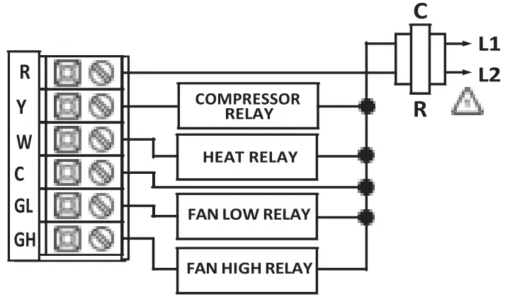 Typical 1H/1C System: 1 Speed Fan
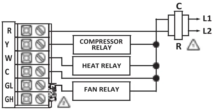 Typical 1H/1C Heat Pump System: 2 Speed Fan
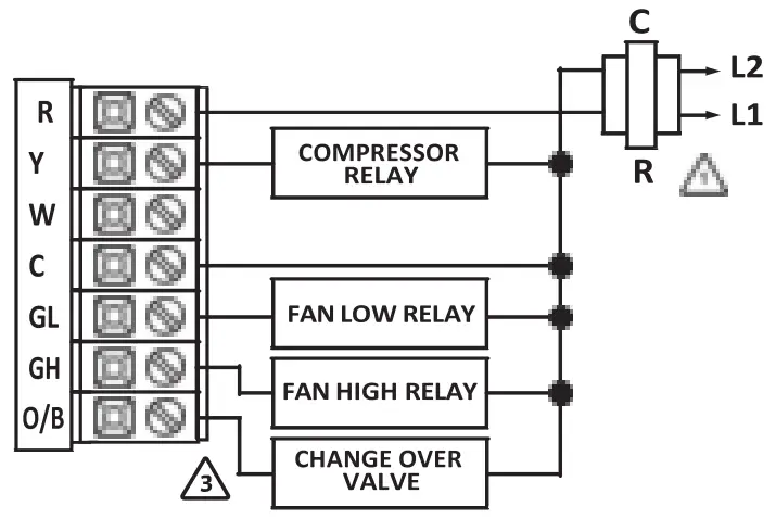 Typical 2H/1C Heat Pump System: 2 Speed Fan
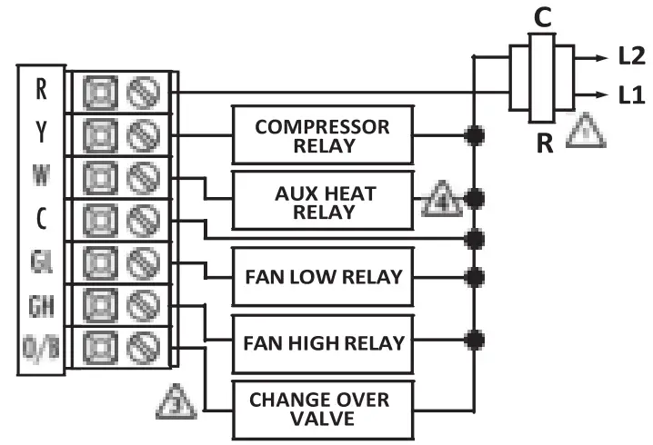
![]() Note:
Note:
Most PTAC systems support two speed fan operation. In a single speed fan PTAC system or conventional single speed fan system, a jumper should be installed between GL and GH on the thermostat.
Technician Setup
Fan OperationSetup Electric: The thermostat operation jumper pin should be put in the ELEC position. This setting allows the thermostat to operate the fan during a call for heat. Most PTAC systems will require ELEC Fan Operation Setup.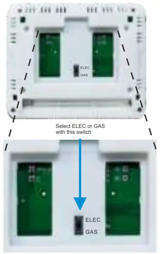 Gas: For systems that control the fan during a call for heat, put the jumper pin into the GAS position.
Technician Setup Menu
- Set the thermostat system switch to OFF.
- To enter Tech Setup Menu,press and hold “+”and “-“together for 3 seconds.
- Use “+”and”-“to select desired setting for each option.
- Tap “+”and “-“together to move next option.
- To exit Tech Setup Menu,move system switch or wait for 15 seconds.
| Tech Setup Steps | Lcd will show | Adjustment options | Defult | |
| Room Temperature Calibration | • This feature allows the installer to change the calibration of the room temperature display. For example. if the thermostat reads 70′ and you would like it to read 72′ then select +2. | You can adjust the room temperature display to read up to 4′ above or below the factory calibrated reading. | ||
| Pair | Transmitter and receiver pair code | Press and hold “+” for 3 seconds until “LE” is flashed. Then release | ||
| F or C | Select for Fahrenheit temperature read out select C for Celsius read out. | F for Fahrenheit C for Celsius | ||
| Compressor Cycle cle Delay | The compressor short cycle delay protects the compressor from short cycling. This feature will not allow the compressor to be turned on for 5 minutes after it was last turned off. | Selecting ON will not allow the compressor to be turned on for 5 minutes after the last time the compressor was switched off. Select OFF to remove this delay. | ||
| Change Over Valve Selection | Select 0 for a changeover valve that energizes in cooling. Select b for a change over valve that energizes in heating. | 0 for cooling changeover valve.b for heating changeover valve. | ||
| Heat Pump | When turned on the thermostat will operate a heat pump.Y will be the first stage of heat & W will be the second stage of heat. | OFF configures the thermostat for non heat pump systems. ON configures the thermostat for heat pump systems. | ||
| Heating Temperature Setpoint Limit | This feature allows you to set a maximum heat setpoint value.The setpoint temperature cannot be raised above this value. | 44.0′ – 90.0′ F 7.0′ – 32.0′ C | ||
| Cooling Temperature Setpoint Limit | This feature allows you to set a minimum cool setpoint valve.The setpoint temperature cannot be lowered below this value. | 44.0′ – 90.0′ F 7.0′ – 32.0′ C | ||
Swing Setting
- Set the thermostat system switch to the desired position (COOL or HEAT).
- Press and hold “+”and “-“together for 3 seconds.
- Use “+”and “-” to adjust desired swing setting (The display reads in tenths of a degree.)
- To exit,move system switch or wait for 1 seconds.
| Swing Settings | LCD Will Show | |||
| Cooling Swing (SYSTEM COOL) | The swing setting, ften calleclacyde rate”, “differential° or ‘anticipation” is adjustable. A smaller wing setting will cause more frequent cycles and a larger swing etting will cause fewer cycles. | The cooling swing setting is adjustable from 0.2′ to T. For example: A swing setting of 0.5′ will turn the cooling on at approximately 0.5* above the setpoint and turn the cooling off at approximately 0.5′ below the setpoint. | ||
| Heating Swing (SYSTEM HEAT) | The swing setting, ften called”cyde rate”, “differential or ‘anticipation” is adjustable. A smaller wing setting will cause more frequent cucles and a larger swing etting will cause fewer cycles | The heating swing setting is adjustable from 0.T to T. For example: A swing setting of 0.5′ will turn the heating on at approimatety 0.5′ below the setpoint and turn the heating off at approximately 0.5′ above the setpoint. | ||
Swing Setting
The second stage of Heat will turn on at 2x the swing setting. The second stage will turn off when ‘Ix the swing is reached. For example, if the swing setting is 0.8° for heating and the thermostat is set at 70° F, the first stage will turn on at approximately 69.2° F. The second stage will turn on at 68.4°F and the first will turn off at 70.8° F.
RF Pairing
- Receiver: Use a slender object into the hole and keep it depressed (for approximately 5 seconds) until the red LED starts flashing.
- Transmitter: Turn the SYSTEM switch to OFF. Press and hold”+” and “-” together for 3 seconds to access the interface of room temperature calibration. Press and hold”+” and “-” together until”LE” is displayed on the LCD.Then press and hold “+” for 3 seconds , the transmitter will transmit the code signal. When the red LED on the receiver stops flashing, indicating that the code is successful.
Acti ate W Go t. Settings
Specifications
MMW-2 Thermostat
| The display range of temperature | . 32°F to 99°F (1°C to 40°C) |
| The control range of temperature.. Load rating | .. 44°F to 90°F (7°C to 32°C) |
| 1 | 1 amp per terminal, 1.5 amp maximum all terminals combined |
| Swing (cycle rate or differential) | Heating is adjustable from 0.2° to 2.0° Cooling is adjustable from 0.2° to 2.0° |
| Power source | 18 to 30 VAC, NEC Class II, 50/60 Hz for hardwire Battery power from 2 MA Alkaline batteries |
| Operating ambient | 32°F to +105°F (0°C to +41°C) |
| Operating humidity | 90% non-condensing maximum |
| Dimensions of thermostat | 120 x 98 x 28MM |
| Operating Frequency | 433.92MHz |
![]()


