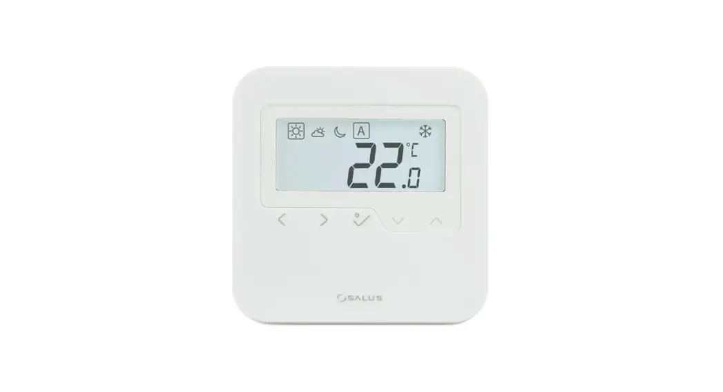
![]() HTRS-RF Wireless Digital Thermostat
HTRS-RF Wireless Digital Thermostat
Instruction Manual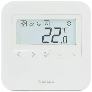
Introduction
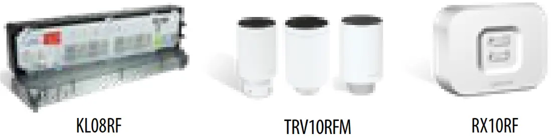
HTRS-RF(30) is a wireless digital room thermostat compatible with devices that are part of the iT600 series, such as: KL08RF wiring centre, TRV10RFM thermostatic radiator valve and RX10RF boiler receiver. If you want the thermostat to control the devices via Internet (Online Mode), please use the UG600 universal gateway and connect it to the SALUS Smart Home app. You can also use the thermostat to control the devices locally without Internet connection (Offline Mode) but in this case the communication between devices must be done using the CO10RF coordinator.
Product Compliance
This product complies with EMC 2014/30/EU, LVD 2014/35/EU, RED 2014/53/EU and RoHS 2011/65/EU. Full text of the EU Declaration of Conformity on www.saluslegal.com ![]() 2405-2480MHz; <14dBm
2405-2480MHz; <14dBm![]() Safety Information
Safety Information
Use in accordance with the regulations. Indoor use only. Keep your device completely dry. Disconnect your device before cleaning it with a dry cloth.
Wiring diagram
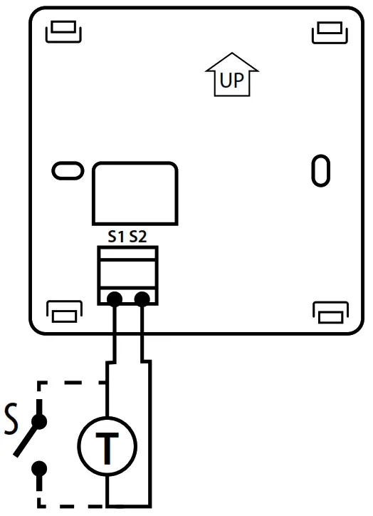
Power supply: 2 x AA alkaline batteries
S1 & S2 terminals:– external temperature sensor (air or floor)
– external switch (occupancy sensor)
Mounting: surface mounting (after removing the back case)
LCD icons
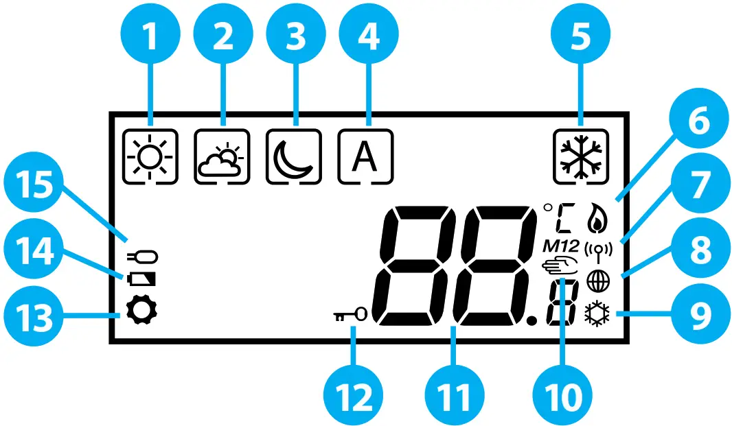
- Comfort temperature
- Standard temperature
- Reduced temperature
- Auto mode
- Frost protection mode
- Heating Mode ON
- RF signal
- Internet connection
- Cooling Mode ON
- Manual Mode/Temporary Override
| Mode selection. Long press Short press | Decrease or increase Setpoint Temperature. | OK key. Short press to confirm selection. Long press to save and return to main screen. |
Button combinations
| Press and hold the buttons simultaneously to lock or unlock the keypad. | Press and hold the buttons simultaneously to enter installer mode. |
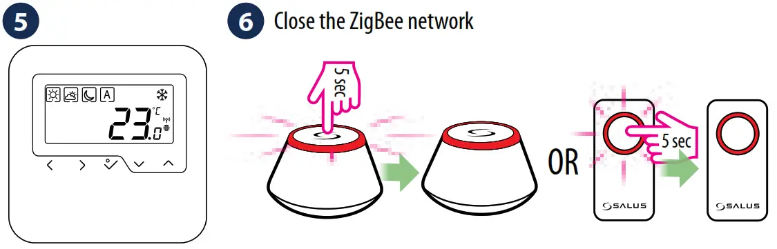
Zigbee network coordinators
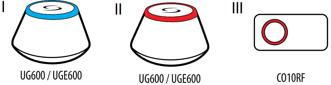
I. Online: connected to the Internet using the UG600 universal gateway.
II. Offline: with the possibility of connecting to the Internet using the UG600 universal gateway.
III. Offline: without any possibility of connecting to the Internet using the CO10RF coordinator.
Select the device that is going to be controlled by the thermostat and the type of Zigbee network coordinator you want to use. Install the devices according to the instructions attached to each product.
Power up
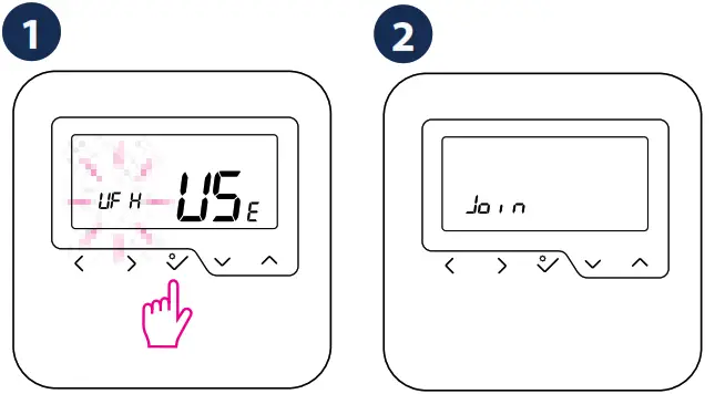
After inserting the batteries, the thermostat will display the software version and it will power up.
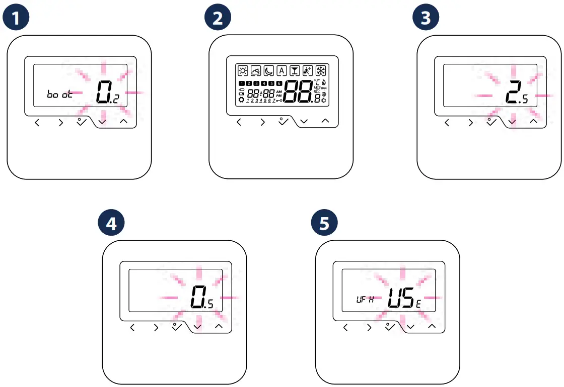
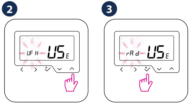
After the first power up, you can choose to pair the thermostat either with underfloor heating (UFH) or with radiators (rAd):![]() : KL08RF wiring centre
: KL08RF wiring centre![]() : TRV10RFM thermostatic radiator valve
: TRV10RFM thermostatic radiator valve
Extended configuration
Extended configuration should be used only if you want to pair the thermostat with the boiler receiver. To do so, press the buttons shown below simultaneously until all visible icons flash once.
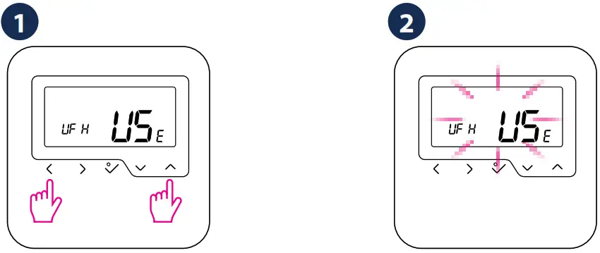
3. Choose the device type according to the screens below:![]() : Undefloor heating
: Undefloor heating![]() : Radiator heating
: Radiator heating![]() : RX10RF in RX1 mode
: RX10RF in RX1 mode![]() : RX10RF in RX2 mode
: RX10RF in RX2 mode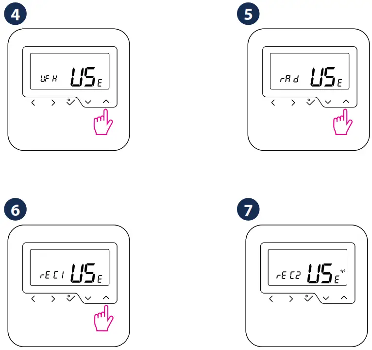
OFFLINE PAIRING PROCEDURE
The offline pairing method should be used by non-internet users only.![]() WARNING! Do not use CO10RF coordinator with UG600 simultaneously.
WARNING! Do not use CO10RF coordinator with UG600 simultaneously.
Pairing with the Wiring Centre
Select ![]() on the LCD.
on the LCD.
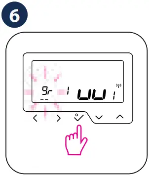
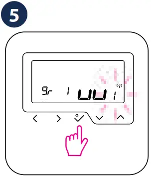 Select the wiring centre number using
 ![]() or
or ![]() (max 9). Confirm your choice by pressing
(max 9). Confirm your choice by pressing ![]() .
.
.
Select the group number (offline only) using ![]() or
or ![]() . Confirm your choice by pressing
. Confirm your choice by pressing ![]() .
.
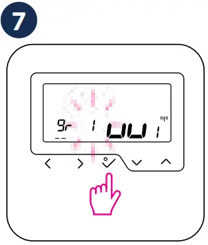
Select the zone number using ![]() or
or ![]() .Confirm your choice by pressing
.Confirm your choice by pressing ![]() .
.
Pairing with the TRV
![]() WARNING! You can connect up to 6 TRVs to one thermostat.
WARNING! You can connect up to 6 TRVs to one thermostat.
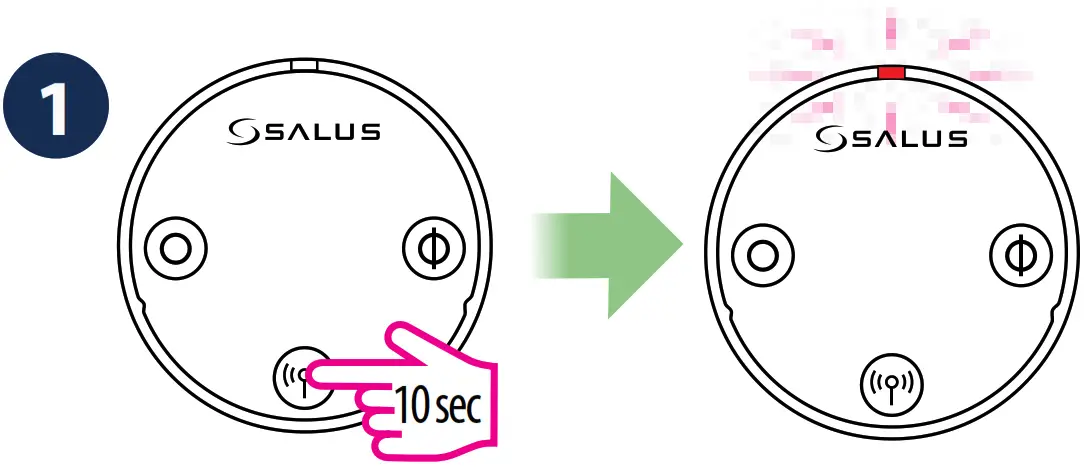
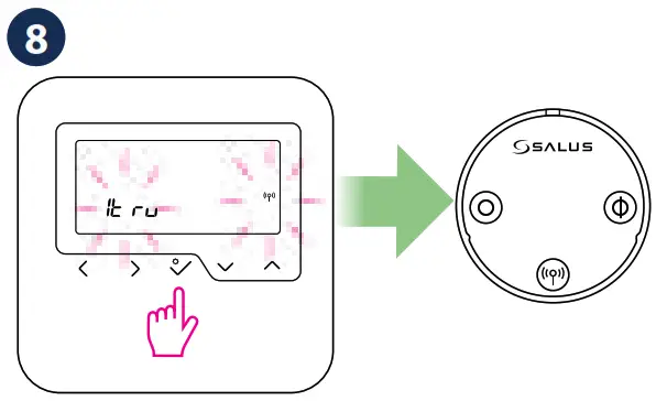
Press and hold the ![]() button for 10 seconds. The LED will start flashing red.
button for 10 seconds. The LED will start flashing red.
Select ![]() on the LCD
on the LCD
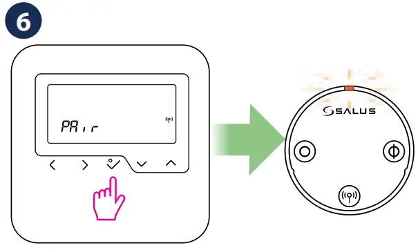
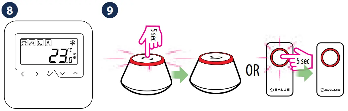
Press ![]() to confirm the pairing with the TRV.
to confirm the pairing with the TRV.
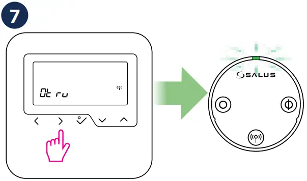
Press ![]() . The LED on the TRV will flash green one time and then it will turn off.
. The LED on the TRV will flash green one time and then it will turn off.
The LCD will display the number of paired devices.Press ![]() to finish.
to finish.
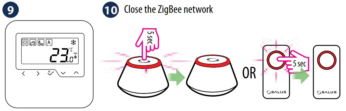
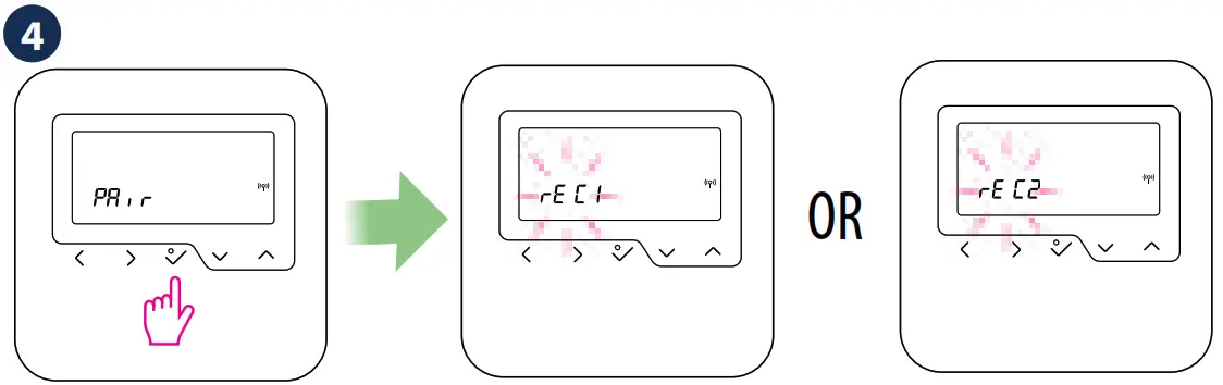
Pairing with the boiler receiver
![]() WARNING! In a ZigBee network, you can use only one RX10RF configured as RX1 and only one RX10RF configured as RX2.
WARNING! In a ZigBee network, you can use only one RX10RF configured as RX1 and only one RX10RF configured as RX2.
In order to pair directly the thermostat with the boiler receiver, please follow the Extended configuration procedure.
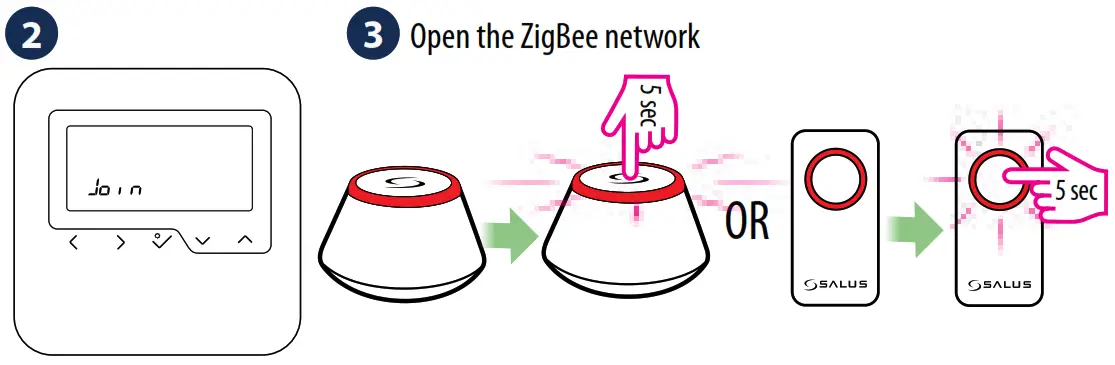
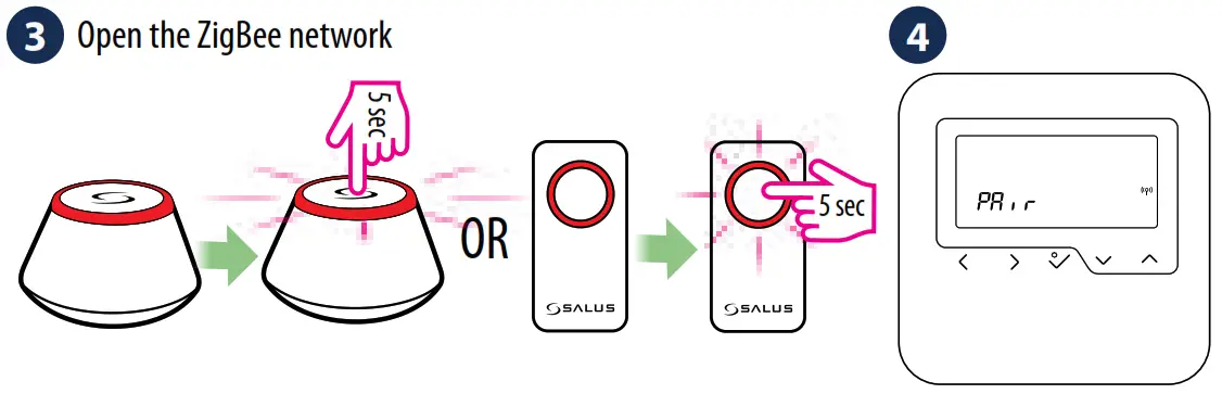
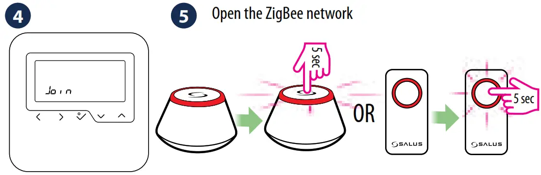
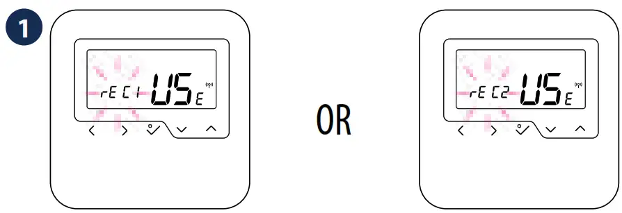
ONLINE PAIRING PROCEDURE
Please use the online pairing method when you are using UG600 to configure your system. Follow the on-screen instructions to complete the setup.
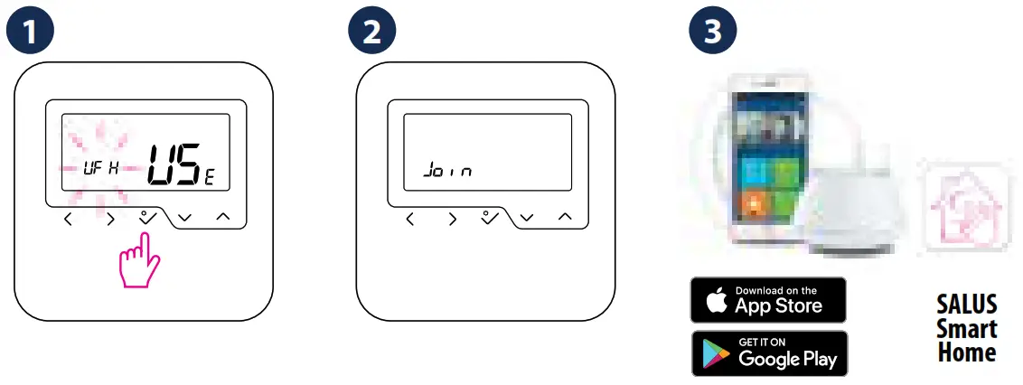
Go to the App
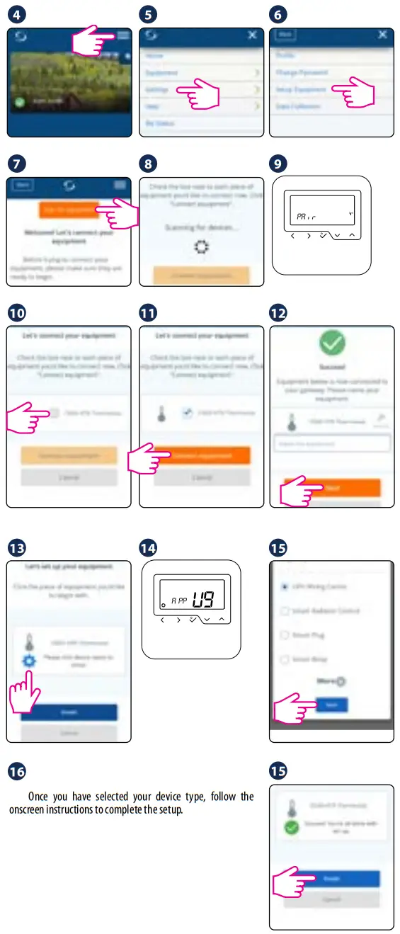
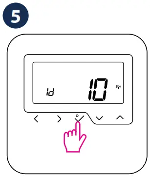
Identify paired devices
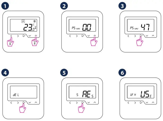
Go to Installer Mode, select parameter 00 and press ![]() .
.
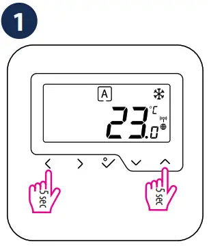

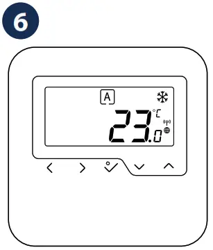
 Press
Press ![]() to exit installer mode.
to exit installer mode.
Change temperature setpoint
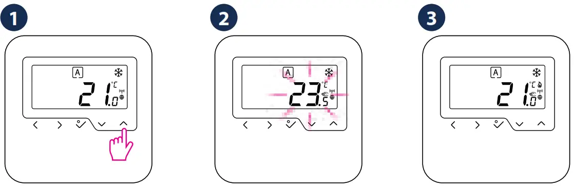
If thermostat works in AUTO mode, then the overwritten temperature (temporary override) will be maintained until next program. In manual mode and frost protection mode temperature change is permanent.
Factory Reset
Head Office:
SALUS Controls plc
SALUS House
Dodworth Business Park South,
Whinby Road, Dodworth,
Barnsley S75 3SP , UK.
T: +44 (0) 1226 323961
[email protected]
[email protected]
UK: [email protected]
tel: +44 (0) 1226 323961
SALUS Controls is a member of the Computime Group
Maintaining a policy of continuous product development SALUS Controls plc reservthe right to change specification, design and materials of products listbrochure without prior notice.
For PDF Installation guide please go to www.salus-manuals.com
Issue date: Apr 2019
Version: V019
 531MSLG3CF132
![]()
 Wireless Digital Thermostat User Manual")
 Wireless Digital Thermostat User Manual")
 Wireless Digital Thermostat User Manual")

 Thermostat User Guide")


 Wireless Room Thermostat User Guide")


