
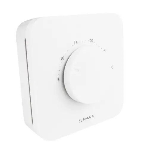
SALUS HTR-RF(20) Wireless Room Thermostat
Introduction
HTR-RF(20) is a wireless dial room thermostat used for underfloor heating and it is compatible offline with CO10RF coordinator and online with SALUS Smart Home system (UG600/UGE600).
Product Compliance
This product complies with the essential requirements and other relevant provisions of Directives 2014/53/EU and 2011/65/EU. The full text of the EU Declaration of Conformity is available at the following internet address: www.saluslegal.com
2405MHz-2480MHz; <14dBm (Zigbee)
Safety Information
Use in accordance with the regulations. Indoor use only. Keep your device completely dry. Disconnect your device before cleaning it with a dry cloth.
Note: Always isolate the AC Mains supply before installing or working on any components that require 230 VAC 50Hz supply.
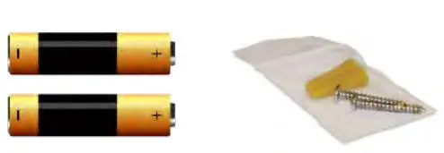
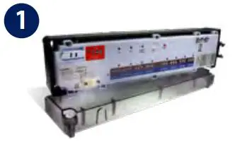
Box content
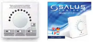
- HTR-RF(20) Thermostat
- Quick Guide
- 2 x AA alkaline batteries
- 2 x fixing screws
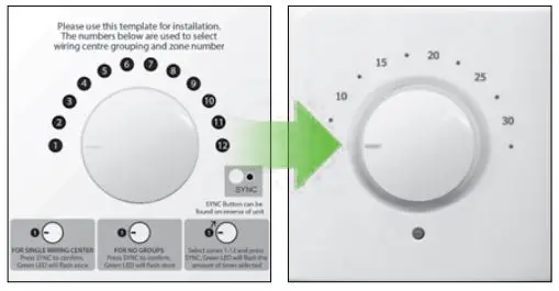
Overlay Information
For reference only. The image on the left explains the correlation between the temperature scale and the pairing scale. To be used for the initial set-up or in case of Lost Link Error. Please keep the sticker on until installation is complete.
LED Indication
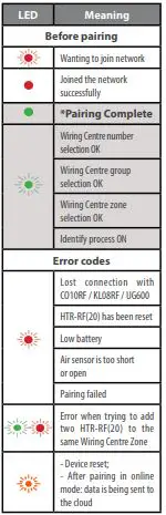
* Only in offline mode
Note: When thermostat is calling for heating/cooling, the LED will be OFF. If you encounter the lost link error, repeat the Pairing procedure.
Installation
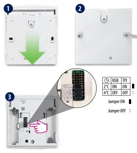
Make your jumper settings
| Jumper | Feature | Default |
| TPI*/SPAN | TPI (jumper ON) or Span 0.5°C (remove jumper) | TPI ON |
| NSB** | Night Setback ON (jumper ON) or OFF (remove jumper) | ON |
| Setback value*** | -2°C (jumper ON) or -4°C (remove jumper) | -2°C for heating and +2°C for cooling |
*TPI will determine the pattern of your heating periods and will adjust it so that the temperature point will be maintained longer.
**NSB will only operate if there is a master thermostat set on the Wiring Centre. If there is no master set, there’s no need to remove the jumper.
***If you have a master thermostat connected to your system and NSB is active, NSB will automatically adjust the setback value according to the selection of the jumper.

- Make sure that the thermostat dial is set in position 1.
- Insert the batteries.
- Check the status of the HTR-RF(20) during the first power up. Flashing RED for 2 sec = NOT PAIRED. Flashing GREEN for 2 sec = PAIRED. If HTR-RF(20) flashes green, but you need to re-pair it, please check the Reset section.
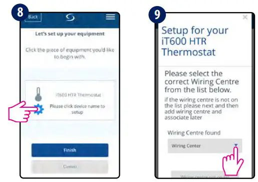
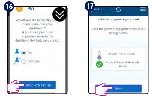
Pair (online)
Please use the online pairing method when you are using UGE600 to configure your system. Follow the on-screen instructions to complete the setup.
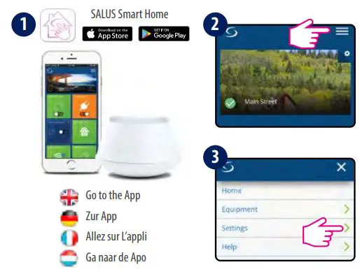
Go to the App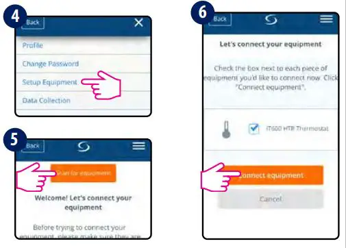
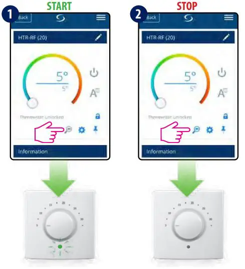
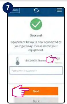 Optional: press the magnifying glass symbol. You can identify your device and rename it.
Dial Function
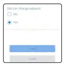
In order to access the dial function menu, press the settings symbol > advanced settings > next.
Dial can change setpoint:
No – dial disabled (control through the app only)
Yes – dial can override the app setpoint
Pair (offline)
The offline pairing method should be used by non-internet users only.
WARNING! Do not use CO10RF coordinator with UGE600 simultaneously.
For more Wiring Centres, Groups or Zones please move the dial in the desired position. Note: The number of times the LED flashes green will correspond with the number of the Wiring Centre, of the Groups or of the Zones selected.
Install the wiring centre according to the instructions attached to the product.
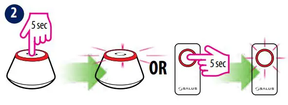
Open the ZigBee network
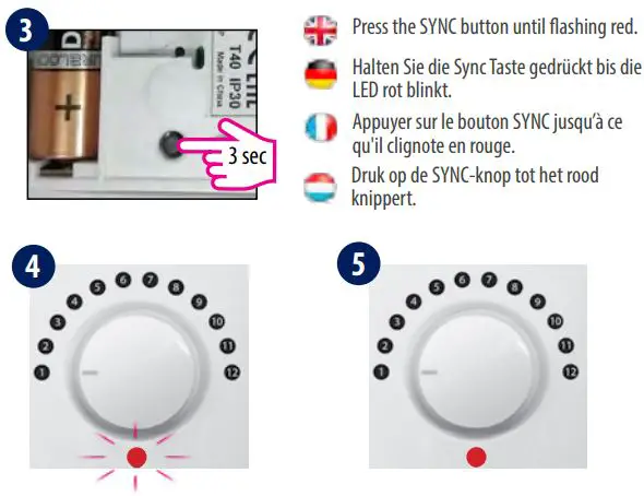
Press the SYNC button until flashing red.
HTR-RF(20) has joined the network once the LED is solid red.
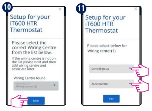
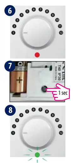
Select the Wiring Centre number (up to 9 centres)
1 WC=position 1; 2
WC=position 2; 9
WC=position 9
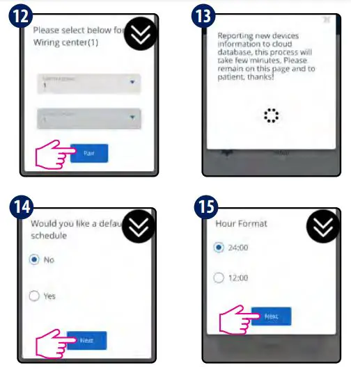
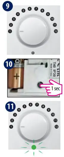
Select the Group number
No Grouping=position 1;
Gr1=position 2;
Gr2=position 3
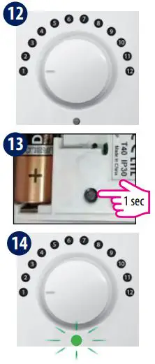
Select the Zone number (up to 12 zones)
Zone 1=position 1;
Zone 2=position 2;
Zone 12=position 12
 Close the ZigBee network
Identify (online)
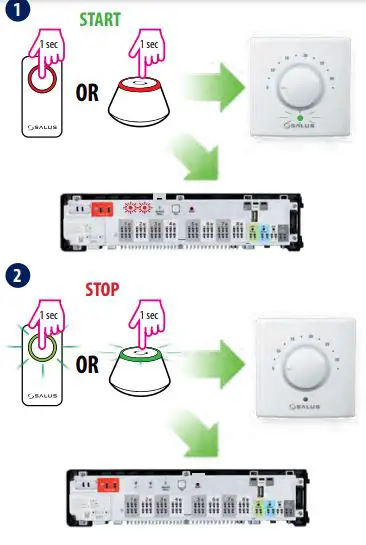
Identify (offline)
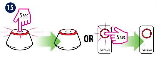
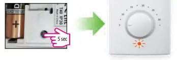
Reset

 Thermostat User Guide")
 Wireless Digital Thermostat User Manual")


 Wireless Digital Thermostat User Manual")

 Wireless Digital Thermostat User Manual")


