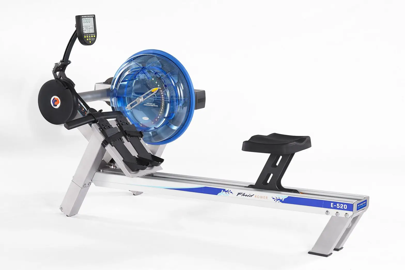
FIRST DEGREE FITNESS FR S-350 Indoor Rower
Training with the S-350
- As with any piece of fitness equipment, consult a physician before beginning your S- 350 exercise program.
- Follow instructions provided in this manual for correct foot position and basic rowing techniques.
CAUTION
- The S-350 can stand vertically for storage. When doing so, please follow the instructions given on the assembly section of this manual.
- Keep hands away from moving parts, as indicated by the warning sticker on the mainframe of your machine and inside the PVC rear cover.
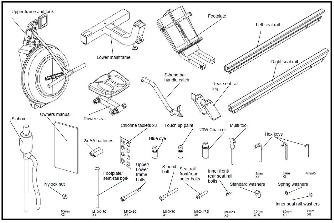
S-350 Box Contents
S-350 Assembly Instructions
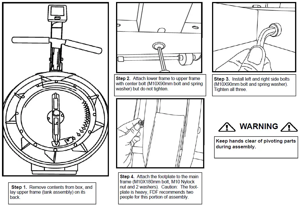
- Step 1. Remove contents from box, and lay upper frame (tank assembly) on its back.
- Step 2. Attach lower frame to upper frame with center bolt (M10X90mm bolt and spring washer) but do not tighten.
- Step 3. Install left and right side bolts (M10X90mm bolt and spring washer). Tighten all three.
- Step 4. Attach the footplate to the main frame (M10X180mm bolt, M10 Nylock nut and 2 washers). Caution: The foot-plate is heavy, FDF recommends two people for this portion of assembly.

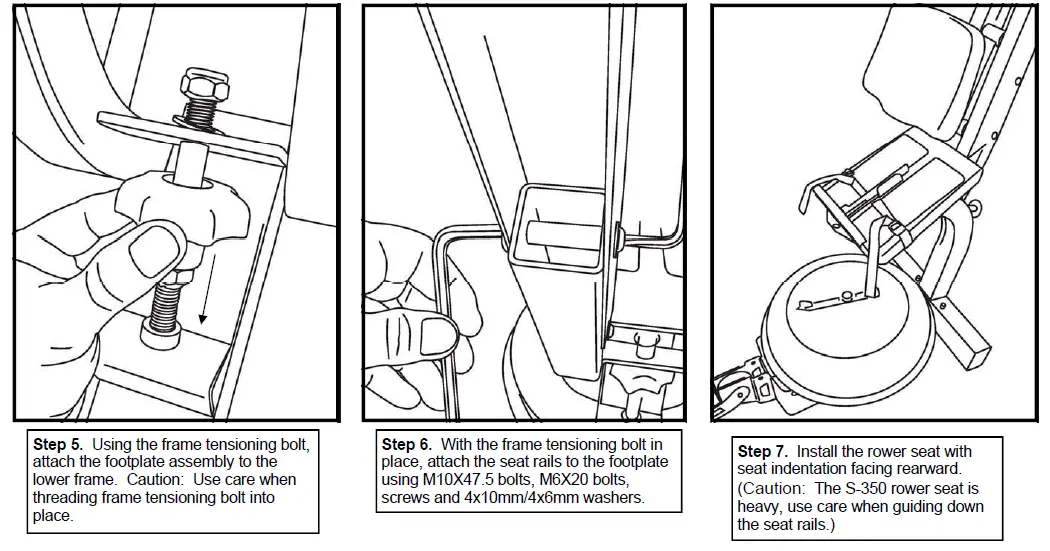
- Step 5. Using the frame tensioning bolt, attach the footplate assembly to the lower frame. Caution: Use care when threading frame tensioning bolt into place.
- Step 6. With the frame tensioning bolt in place, attach the seat rails to the footplate using M10X47.5 bolts, M6X20 bolts, screws and 4x10mm/4x6mm washers.
- Step 7. Install the rower seat with seat indentation facing rearward.
(Caution: The S-350 rower seat is heavy, use care when guiding down the seat rails.)
- Step 8. Install the rear leg assembly to the seat rails using M10X47.5 bolts, M6X20 Allen key screws and 4x10mm/4x6mm washers.
- Step 9. With the tensioning bolt, seat and rear leg in place you may lower the S-350 to its operating position and con-tinue with the final steps of assembly.
- Step 10. Bolt the rear to the upper frame. (M10X80mmbolt, Nylock nut and 2 washers)
- Step 11. Insert the front of the handle catch bar (S-bend) into the foot plate.
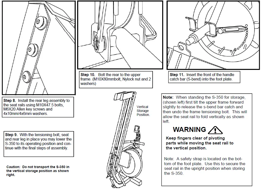
Note: When standing the S-350 for storage, (shown left) first tilt the upper frame forward slightly to release the s-bend bar catch and then undo the frame tensioning bolt. This will allow the seat rail to fold vertically as shown left.
WARNING: Keep fingers clear of pivoting parts while moving the seat rail to the vertical position.
Note: A safety strap is located on the bottom of the foot plate. Use this to secure the seat rail in the upright position when storing the S-350.
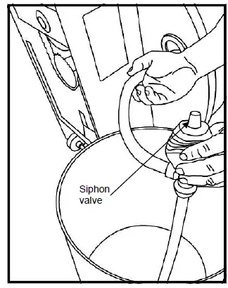
Fill tank as shown left. Use the right plug only for filling.
Fill with adjuster handle at level 16 only.
Once filling is com-plete, use a coin or large blade screw-driver to tighten tank plug into place.
Water Treatment Proce-dures:
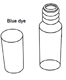
- Add Chlorine tablet.
- Wait a minimum of 72 hours. Then add very small amount of blue dye and check for desired color. Im-portant! Do not add blue dye for at least 72 hours following Chlorine treat-ment. The blue dye adds visual appeal as well as cut-ting down the amount of light affecting the tank water, thus extending the amount of time between water treatments.
Tank filling and Water Treatment
- Filling requires a large bucket (not supplied) and the Fluid Rower siphon (included). A filling will take approximately 7.6 liters of water.
- Unscrew the right tank plug on the rear of the fluid tank and insert the flexible tube into the rear of the tank while keeping the rigid hose in the bucket. Note: The siphon tube may be impeded by one of the impeller blades. Use the siphon only to push the impeller down slightly.
- Move the adjuster handle to level 16, and begin filling.
Note: The siphon valve must be closed to allow siphoning action to occur. Tip: Placing the bucket in an elevated position will allow the siphon to continually pump water into the tank. Do not fill past the calibration mark indicated on the tank!
Note: Opening the siphon valve will stop the pumping action. Use this feature to avoid water spillage when nearing filling completion. - Once the filling is complete (to the proper calibration level as indicated on the tank), follow water treatment schedule as shown.
Caution: Use a drop cloth under the tank both when filling the tank and adding blue dye to avoid staining floor or carpet
How to row.
- Begin the stroke comfortably forward and push strongly back with your legs while keeping your arms and back straight.
- Begin to pull your arms back as they pass over your knees and continue the stroke through to completion rocking slightly back over your pelvis.
- Return to the starting position and repeat.
How often?
Begin with 5 minute training sessions once a day and aim for around 2:30 to 2:45 for 500m time. Row at a pace that keeps the water circulating continuously between strokes.
Progress a few minutes more each day until you are comfortable with 30-45 minutes training time 3 or 4 times a week.
This is sufficient to provide aerobic endurance benefits, muscle toning and sufficient calorie burning to form part of a weight loss pro-gram.
CAUTION
Always consult a doctor before beginning an exercise program. Stop immediately if you feel faint or dizzy. 
Long term water treatment and basic operation
Important: Do not fill past the calibration mark as indicated on the tank leve l sticker or water spillage may occur. See tank filling/water treatment page for details.
Long term water treatment:
Do not use any water treatment other than the tablets supplied with this machine. For replacement tablets, contact your local First Degree Fitness distributor.
Water treatment schedules for the S-350 will vary according to the fluid tanks exposure to sunlight, but expect 8-12 months near a bright, sunlit win-dow and 2 years or more for a darker location. At the point of finding the water slightly cloudy, add a Chlorine tablet. Remember to wait 72 hours following the chlorine tablet before adding the blue dye as the Chlorine tab-let is extremely concentrated.
Caution: It is critical that a drop cloth be used under the fluid tank whenever the tank plug is opened for water treatment.
Resistance: The level of resistance is determined by the level indicator located on the front of the tank. Level one indicates lightest resistance, level sixteen repre- sents heaviest resistance. Allow three to four strokes after adjusting resis-tance handle for the correct resistance level to be achieved.
Frame levelers: T here are 3 frame levelers on the S-350. If rocking is present, then sim-ply raise one of the front lower frame levelers until stability is achieved.
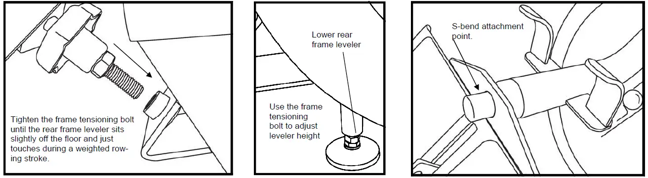
Note: The lower rear frame leveler is designed to sit slightly off the ground. See following page and illustrations as discussed in the Fine Tuning the S-350 section of this manual. This leveler height is preset from the factory, and is adjusted using the frame tensioning bolt as de-tailed on the following page.
Heel support adjuster: The S-350 has a unique and easy to use Heel Support Adjuster. Simply slide the Adjuster up or down to the required position. This should place the ball of your foot directly under the horizontal Foot Straps. Secure Foot Straps. The Heel Support allows the user to row without shoes if desired.
Fine tuning the S-350
Caution: Use care when threading the frame tensioning bolt.
The frame tensioning bolt must be adjusted properly for optimum performance. Symptoms of an improperly adjusted frame tensioning bolt will include front frame shak-ing and the S-bend attachment point moving during rowing. If either of these symptoms appear, than take the following steps.
- If the S-bend is moving in and out of the attachment point during hard rowing, the tensioning bolt may be over-tightened. Loosen slightly and check performance. This will also weight the S-bend handle catch into the footplate attachment point and prevent it from moving.
- If the frame tensioning bolt is threaded too loosely, the mainframe rear leveler will be resting on the floor. This will cause the rower to lift slightly on the front during hard rowing and not be smooth. Tighten the frame tensioning bolt until you see the rear frame leveler rise slightly off the ground, but can just touch the floor during a weighted rowing stroke.
- Once the S-bend is tight and does not move during rowing, and the frame tensioning bolt is threaded to the correct depth, the adjustment will be complete.
Note: The frame tensioning bolt may require slight adjustment for rowers of different weights. For example, a heavier user may require a slightly tighter adjustment on the frame tensioning bolt.
Transporting the S-350 The S-350 can be transported with the frame tensioning bolt in place. Simply lift from the rear of the seat rail until the transport wheels are engaged. The frame will sag slightly as the rower is being moved in this position and the S-bar may drop out of its attachment point. This is normal. Warning! Do not attempt to transport in the vertical (folded) position. Only transport the S-350 in the normal operating position with the frame ten-sioning bolt in place.
General Maintenance
Chain tension and lubrication:
The chain will require periodic tightening and lubrication using the 20-weight oil supplied. This is a general time frame for lubrication which will vary slightly depending on usage.
After first 50 hours of use:
- Remove the Perspex cover.
- Inspect chain for dryness and proper tension. Note: The chain should have approx 3- 5mm of play after tightening with a smooth run on after every stroke.
- Lubricate lightly with the supplied 20 weight oil.
Warning! After lubrication, any excess oil will be thrown onto the inside of the Perspex cover and possibly the floor below. Use a drop cloth both during and after chain lubrication to prevent oil stains.
Repeat after every 100 operating hours to maintain optimum performance.
Warning!
- Keep fingers clear of all moving parts while adjusting the chain!
- Always use a dropcloth under the machine after lubricating the chain to protect floors/carpet from excess oil spatter.
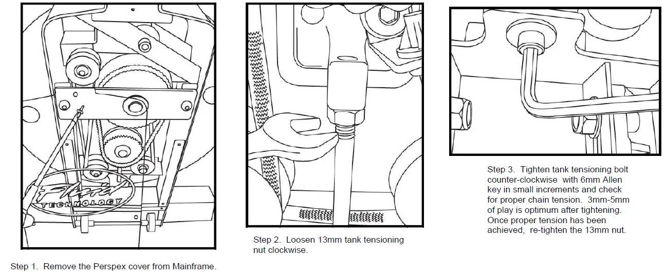
- Step 1. Remove the Perspex cover from Mainframe.
- Step 2. Loosen 13mm tank tensioning nut clockwise.
- Step 3. Tighten tank tensioning bolt counter-clockwise with 6mm Allen key in small increments and check for proper chain tension. 3mm-5mm of play is optimum after tightening. Once proper tension has been achieved, re-tighten the 13mm nut.
Maintenance chart.
| Item | Timeframe | Instructions | Notes |
| Chain and sprockets. | First 50 hours and every hundred hours thereafter. | Follow instructions on previous page. | |
| Seat and seat rails. | Weekly. | Wipe seat rails with lint free cloth. Spray seat rails and seat wheels with a light coat of silicone spray. | |
| Frame. | Weekly. | Wipe down with lint free cloth. | |
| Tank and water treatment. | 12 months to 2 years. | Follow instructions as specified in the “Water Treatment” section of this man- ual. | |
| Bungee cord. | Check every hundred hours for correct tension and for signs of wear. | The bungee cord will last for several years. If a bungee cord change is required, please follow the instructions provided in the “Changing the bungee cord” section of this manual. | |
| Rower belt. | Check monthly for signs of fraying or premature wear. | The Rower belt should never require changing, but should the need arise, please follow the instructions provided in the “Changing the Rower belt” section of this manual. |
Computer Instructions
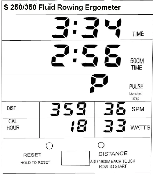
The S-350 Computer:
- TIME: Auto start elapsed time.
- 500M TIME: Time to row 500 meters, updated at the completion of each stroke.
- PULSE: Requires optional receiver and chest strap.
- SPM: strokes per minute updated each stroke.
- WATTS: Indication of watts at Tank level 16
- CAL HOUR: Updated each stroke.
- PROGRAMMING: Computer will auto start.
Note: Computer will reset and begin to count up after 10 seconds of inactivity
Options (Hold button down for one second first to reset computer)
- Add 1000m distance each button push to accumulate required dis-tance then begin rowing.
- Interval training.
Row distance as above.
Stop rowing. Computer will wait 10 seconds then begin a count up to a maximum of 6 minutes to allow you to time your rest interval.
Troubleshooting Guide
| Fault | Probable Cause | Solution |
| Water changes color or becomes cloudy. | Rower is in direct sunlight or has not had water treatment. | Change rower location to reduce direct expo- sure to sunlight. Add water treatment and blue dye or change tank water as directed in the water treatment section of this manual. |
| Rower belt slipping off belt/ bungee pulley. | Bungee not under enough tension. | Tighten bungee cord following the instructions in the Replacing the bungee/shock cord section of this manual. |
| Front of rower lifts slightly during vigorous rowing. | Lower rear frame leveler too high. | Refer to the Fine Tuning section of this manual |
| Excessive frame flex during hard rowing. | Lower rear frame leveler too low. | Refer to the Fine Tuning section of this manual. |
| Computer screen illuminates, but does not register when rowing. | Loose or failed connection. | Check that the computer lead is connected properly. If it is connected then contact your local service center. |
| Excessive Chain noise. | Loose or dry chain. | Loosen tank bolts slightly and then use the tank tensioning bolt to tighten chain. Lubricate with supplied 20-weight oil. Use drop cloth un- der frame. Refer to the Maintenance page, chain tension and lubrication for details. |
| The S-350 computer does not illuminate after battery installation. | Batteries installed incorrectly or need re- placing. | Reinstall batteries in correct position and try again. If the LCD screen fails to illuminate, try rotating the batteries slightly in the computer. If this fails, contact your local service center. |
Changing the Rower belt
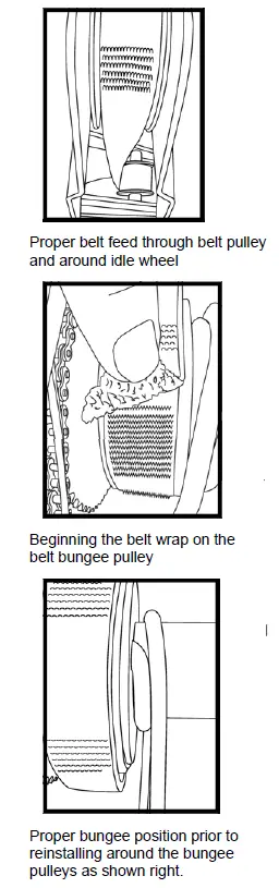
- Proper belt feed through belt pulley and around idle wheel
- Beginning the belt wrap on the belt bungee pulley
- Proper bungee position prior to reinstalling around the bungee pulleys as shown right.
Belt Removal
- To remove the rower belt, simply continue past the normal rowing position rearward until the belt detaches from the belt/bungee pulley.
Replacing the belt - First remove the rear PVC cover at the rear of the machine. Then remove metal inspection plate which is located on the right side of the upper frame to access the belt/bungee pulley.
- Detach the bungee cord at bottom left of frame.
Feed the belt through the top belt pulley with the velcro facing down .
Then feed the belt across the idle wheel as shown (upper left). - Feed the belt onto the belt/bungee pulley slowly clockwise until the rower handle is right to the computer mount. You can check your progress by looking through the inspection plate to make sure the belt is wrapping smoothly as shown left.
Note: The bungee cord will need to be rewrapped around the belt bungee pulley and bungee wheels correctly once the rower belt is position.
Warning: Do not attempt to operate the machine until the bungee cord has been properly re-wrapped. - Unwrap the bungee cord from the belt bungee pulley until you see the placement hole in the belt/bungee pulley. Then, make one clockwise wrap as shown (lower left) and feed the bungee onto the bungee pulleys following the steps below:

Finish by tying off at the bungee attachment point at the bottom left of the inner frame. Approx 5cm of bungee fed through the attachment point should provide the proper tension.
Tip: Keeping the bungee under tension while wrapping will help prevent the bungee from slipping off the bungee pulleys.
Changing the bungee cord
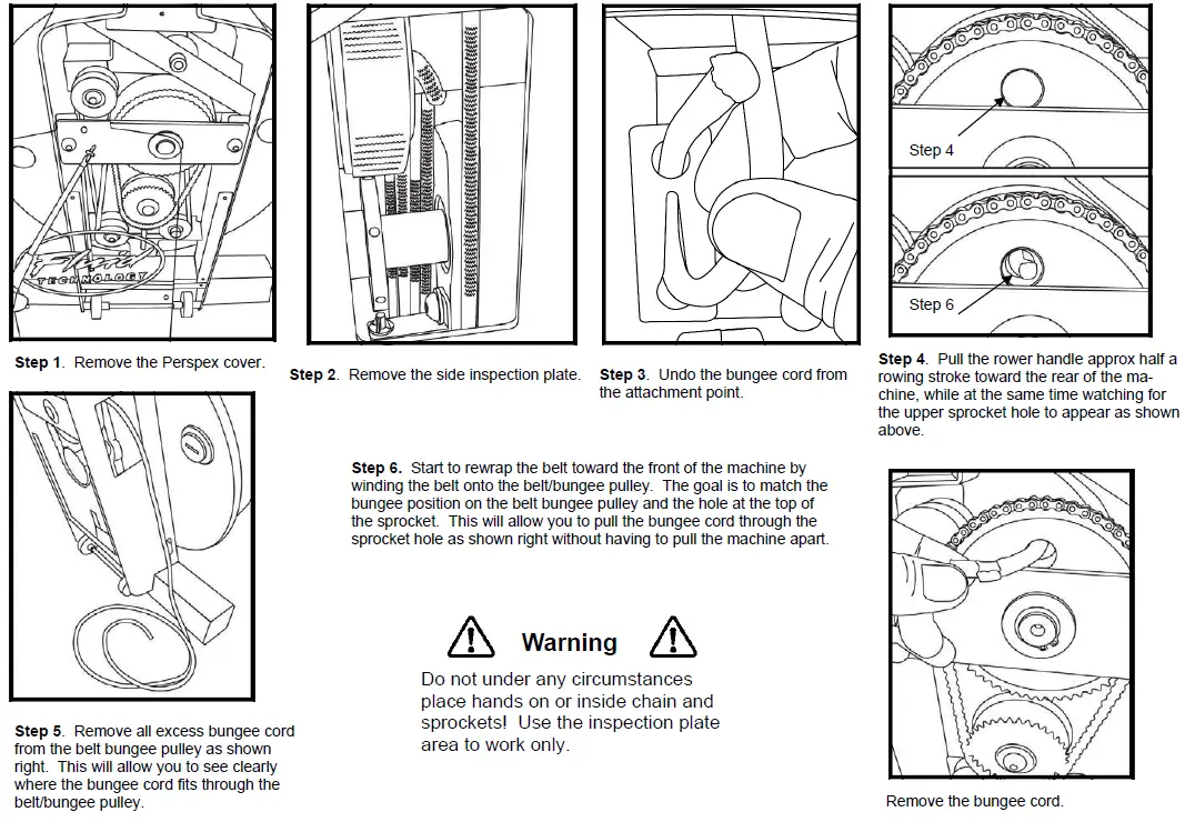
- Step 1. Remove the Perspex cover.
- Step 2. Remove the side inspection plate.
- Step 3. Undo the bungee cord from the attachment point.
- Step 4. Pull the rower handle approx half a rowing stroke toward the rear of the machine, while at the same time watching for the upper sprocket hole to appear as shown above.
- Step 5. Remove all excess bungee cord from the belt bungee pulley as shown right. This will allow you to see clearly where the bungee cord fits through the belt/bungee pulley.
- Step 6. Start to rewrap the belt toward the front of the machine by winding the belt onto the belt/bungee pulley. The goal is to match the bungee position on the belt bungee pulley and the hole at the top of the sprocket. This will allow you to pull the bungee cord through the sprocket hole as shown right without having to pull the machine apart.
Warning: Do not under any circumstances place hands on or inside chain and sprockets! Use the inspection plate area to work only.
- Step 7. Feed the replacement bungee through the sprocket hole and belt bungee pulley as shown. Holding the Idle wheel with one hand as pictured will prevent the belt/bungee and sprocket holes from moving out of alignment when threading the bungee cord. If the two holes move out of alignment while threading the bungee cord stop, remove the bungee cord, realign the holes and try again.
- Step 8. Once the bungee cord is fitted properly and seated flush inside the belt/bungee pulley, thread the rower belt back on to the belt bungee pulley until the rower handle is at its furthest point forward. Then, remove the bungee wraps from the belt/bungee pulley completely. At this point, make one clock-wise wrap of the bungee cord on the belt bungee pulley as shown right. Then, follow the illustrations below to wrap the bungee cords around the bungee pulleys.
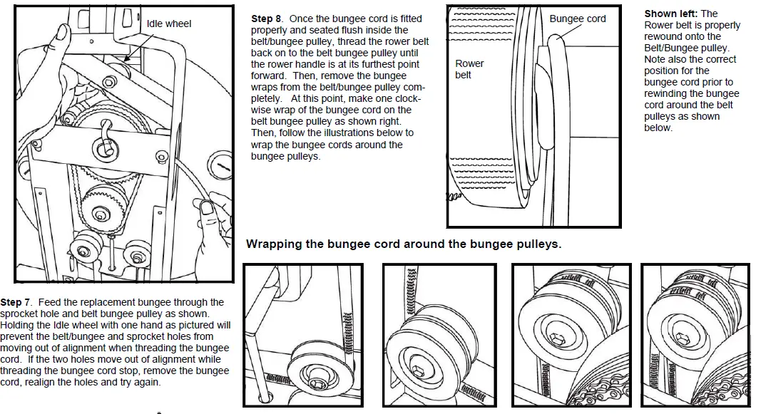
Shown left: The Rower belt is properly rewound onto the Belt/Bungee pulley. Note also the correct position for the bungee cord prior to rewinding the bungee cord around the belt pulleys as shown below.
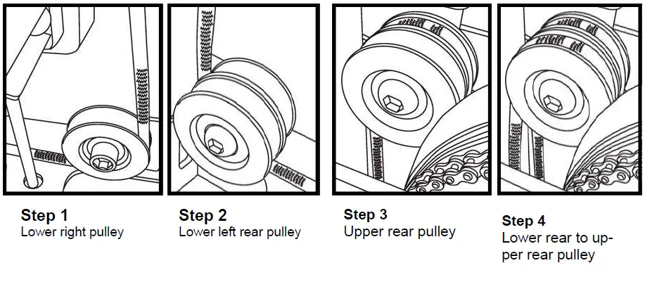
Caution
- Begin with the lower right bungee pulley, taking care to keep the bungee cord behind the frame tensioning bolt as pictured.
- Next, thread the bungee around the lower left rear bungee pulley.
- Then, thread the bungee around the upper left rear bungee pulley.
- Next, thread the bungee around the lower left front bungee pulley, and then up to the upper left front bungee pulley, finishing at the tie off point located at the left lower section of the frame. (See step 2)
Tip: Keeping the bungee cord under slight tension will help prevent the cord from slipping off the bungee pulleys while wrapping.
S-350 Parts list
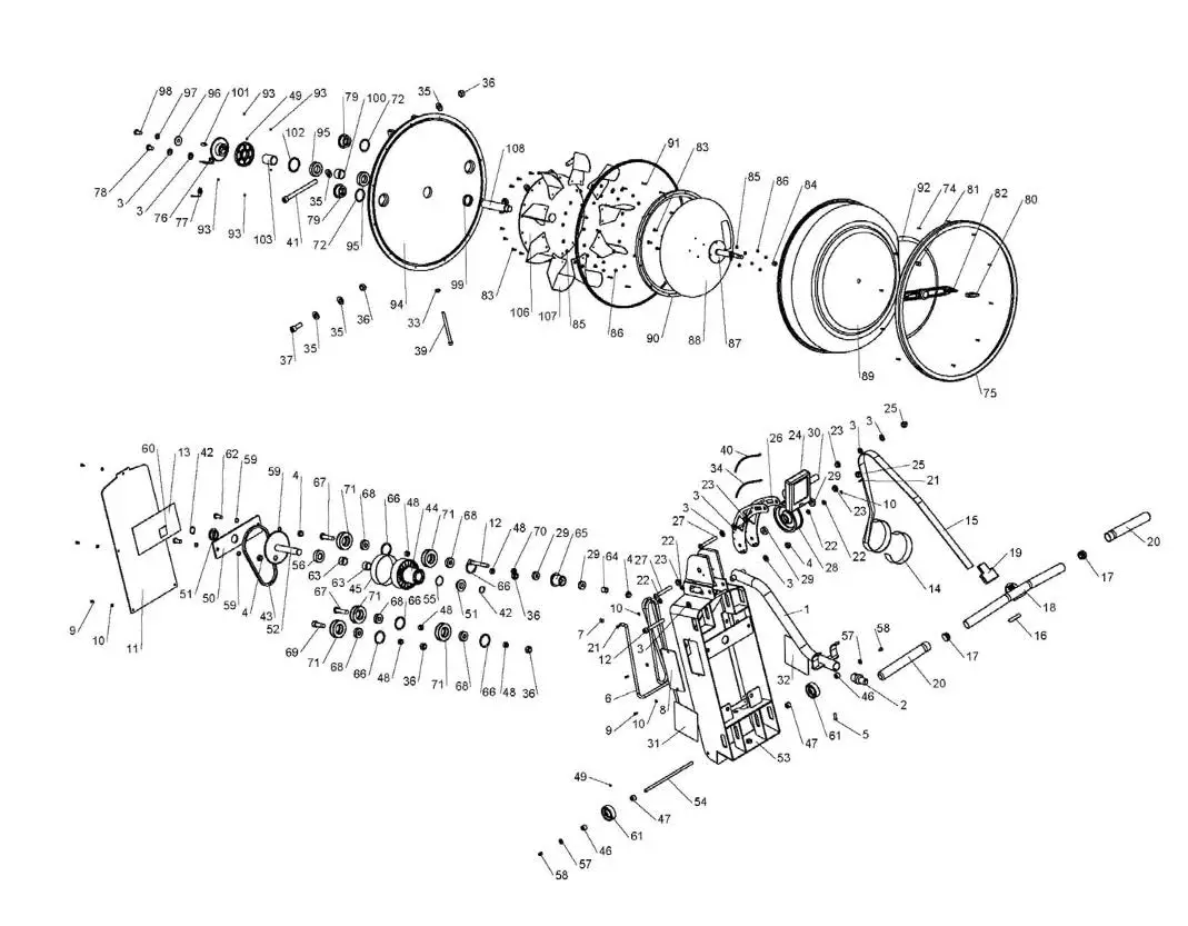
| KEY NO. | QTY. | PART NO. | Description | KEY NO. | QTY. | PART NO. | Description |
| 1 | 1 | 70600 | S-bend handle catch bar | 28 | 1 | 60111 | Belt Pulley |
| 2 | 1 | 71015 | S-bend handle catch bar male end | 29 | 4 | 60112 | Belt pulley bearing 6000ZZ |
| 3 | 8 | 10082 | Washer | 30 | 1 | 60105 | Computer bolt spacer |
| 4 | 4 | 10041 | M10 Nylock nut | 31 | 1 | 81001 | Main frame decal ( R ) |
| 5 | 1 | 10080 | M6x20 bolt | 32 | 1 | 81002 | Main frame decal ( L ) |
| 6 | 1 | 80502 | Bungee cord | 33 | 1 | 71036 | M8 nut (Note: For tank tensioning bolt) |
| 7 | 1 | 60617 | Bungee cord crimped end (included with Bungee cord) | 34 | 1 | 71023 | Heart rate wiring |
| 8 | 1 | 71009 | Inspection plate | 35 | 6 | 10043 | Washer 24x12x2 |
| 9 | 7 | 10070 | M4x10 screw | 36 | 6 | 10042 | M12 Nylock nut |
| 10 | 9 | 10170 | M4 washer | 37 | 2 | 10063 | Tank assembly bolt M12X30mm |
| 11 | 1 | 71019 | PVC Cover | 38 | 1 | 10190 | Washer 26x8x2mm |
| 12 | 2 | 10115 | S-bend M10X80mm mounting bolt | 39 | 1 | 71018 | Bolt M8*110 |
| 13 | 1 | 71032 | PVC Cover decal | 40 | 1 | 71022 | computer wiring |
| 14 | 1 | 60508 | Velcro strip for belt (Note: Combined with 80501 Rowing belt) | 41 | 1 | 10040 | M12x140mm Upper tank mounting bolt |
| 15 | 1 | 80501 | Rowing belt | 42 | 2 | 71008 | C clip STW-20 |
| 16 | 1 | 60505 | Inner rowing handle foam | 43 | 1 | 71010 | Chain 25H-1R |
| 17 | 2 | 60144 | Inner rowing handle plastic end cap | 44 | 1 | 71030 | Belt/Bungee pulley |
| 18 | 1 | 60501 | Rowing handle | 45 | 1 | 60903 | Velcro strip for Belt/Bungee pulley |
| 19 | 1 | 60504 | Handle/belt rubber cover | 46 | 2 | 71002 | Outer axle bushing |
| 20 | 2 | 60506 | Rowing handle rubber grip | 47 | 2 | 71003 | Inner axle bushing |
| 21 | 2 | 71017 | M4x15 bolt | 48 | 5 | 71011 | Bungee pulley spacer |
| 22 | 4 | 60606 | M4 Plastic washer | 49 | 3 | 10052 | Grub screw M4x6mm |
| 23 | 4 | 10114 | Plastic bushing for computer stalk mount | 50 | 1 | 70107 | Main shaft rear bracket |
| 24 | 1 | 81003 | Computer | 51 | 2 | 71005 | Brass oil bushing (short) |
| 25 | 2 | 10097 | M10 dome head nut | 52 | 1 | 70900 | Main shaft/Sprocket |
| 26 | 1 | 70500 | Computer mount | 53 | 1 | 70100 | Upper Main frame |
| 27 | 2 | 10096 | M10x70 bolt | 54 | 1 | 71001 | Transport wheel axle |
| KEY NO. | QTY. | PART NO. | Description | KEY NO. | QTY. | PART NO. | Description |
| 55 | 1 | 71006 | Plastic washer WP32H2 | 82 | 1 | 10184 | Adjuster handle (Includes PU yellow cover #10193) |
| 56 | 1 | 71007 | Plastic bushing | 83 | 22 | 10035 | SUS M4x12 bolt |
| 57 | 2 | 10081 | M6 Washer | 84 | 2 | 10032 | Adjuster shaft O ring |
| 58 | 2 | 10171 | M6x8mmTransport axle bolt | 85 | 22 | 10033 | M4 Washer |
| 59 | 4 | 20151 | M10 washer | 86 | 22 | 10034 | M4 SUS Nylock nut |
| 60 | 1 | 71031 | hand warning decal | 87 | 1 | 10027 | Stainless adjuster shaft |
| 61 | 2 | 71014 | M12x35mm bungee pulley bolt | 88 | 1 | 10028 | Stainless backing plate |
| 62 | 2 | 71025 | M10x25mm main shaft rear bracket bolt | 89 | 1 | 10045 | Polycarbonate tank (Includes #70320 tank decal) |
| 63 | 2 | 71020 | INA Single One way bearing 2016 | 90 | 1 | 10030 | Polypropylene Ring |
| 64 | 1 | 71013 | Idle wheel bushing (long) | 91 | 12 | 10036 | PC tank cover bolt M3x20 |
| 65 | 1 | 60119 | Idle wheel | 92 | 1 | 70320 | Tank decal |
| 66 | 5 | 10086 | C clip RTW-35 | 93 | 6 | 70319 | Rare earth magnet |
| 67 | 2 | 10088 | M12x50mm Bungee pulley bolt | 94 | 1 | 10300 | SMC tank back |
| 68 | 5 | 10085 | Bungee pulley bearing NBN6201ZZ | 95 | 2 | 10012 | NSK 6005ZZ Bearing |
| 69 | 1 | 71024 | M12x35 bungee pulley bolt | 96 | 1 | 10138 | 30×10.2x3mm tank shaft washer |
| 70 | 1 | 71012 | Idle wheel bushing (short) | 97 | 1 | 10139 | M10 Spring washer |
| 71 | 5 | 10084 | Bungee pulley | 98 | 1 | 10083 | M10x20 bolt |
| 72 | 2 | 10039 | Tank plug O-ring | 99 | 1 | 10025 | NBR 37x30x8t Flywheel shaft seal |
| 73 | 1 | 10046 | Large Polycarbonate tank rubber O-ring seal | 100 | 1 | 10145 | 30mmx25.1mmx20.5mm Bearing spacer |
| 74 | 12 | 10062 | M3x12mm Polycarbonate tank cover screw | 101 | 1 | 70317 | 7x7x20mm Key pin |
| 75 | 1 | 10044 | Tank outer rubber ring | 102 | 1 | 10186 | RTW-48 C clip |
| 76 | 1 | 70318 | sensor bracket | 103 | 1 | 70314 | Tank insert bushing (long) |
| 77 | 1 | 10157 | sensor | 104 | 1 | 70315 | Magnetic ring |
| 78 | 1 | 20150 | M10x15mm Sensor bracket mounting bolt | 105 | 1 | 70316 | Upper Sprocket |
| 79 | 2 | 70321 | Tank plug | 106 | 1 | 70303 | Flywheel |
| 80 | 1 | 10193 | PU yellow adjuster handle cover | 107 | 9 | 10047 | Impeller blade |
| 81 | 2 | 10162 | M8x10mm Grub screw | 108 | 1 | 70313 | Impeller shaft |
S-350 Parts list:
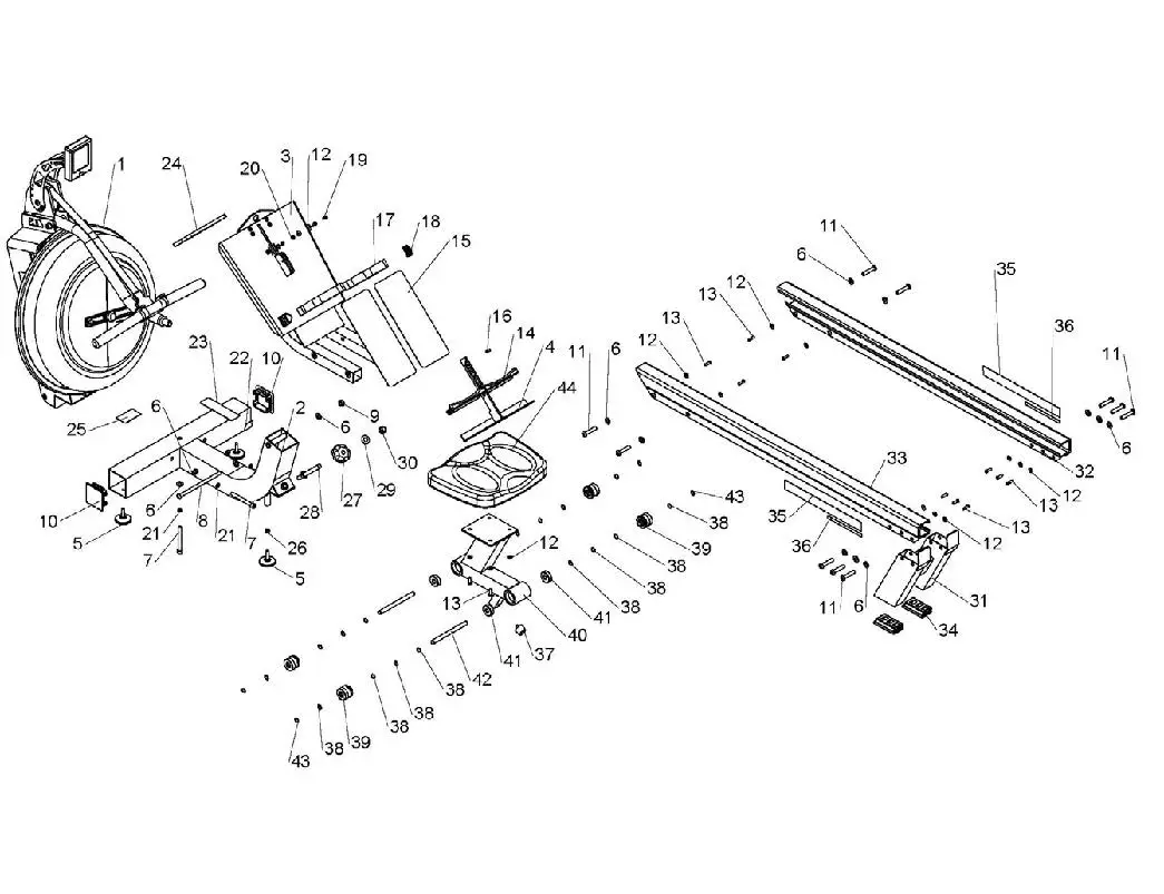
| Key No. | QTY. | PART NO. | Description | Key No. | QTY. | PART NO. | Description |
| 1 | 1 | 80001 | Main frame | 23 | 1 | 81004 | S350 HOW TO ROW Decal |
| 2 | 1 | 80200 | Lower frame | 24 | 1 | 81005 | Safety Strap |
| 3 | 1 | 80700 | Foot plate | 25 | 1 | 10099 | Caution decal |
| 4 | 1 | 11101 | S350 Heel supporter | 26 | 1 | 71036 | M8 nut |
| 5 | 3 | 71016 | Lower frame leveler | 27 | 1 | 70404 | Frame tensioning bolt adjuster knob |
| 6 | 15 | 10082 | 21x10x2mm washer | 28 | 1 | 70411 | Frame tensioning bolt |
| 7 | 3 | 60121 | M10x90mm Upper/lower frame mounting bolt | 29 | 1 | 10043 | 24x12x2mm washer |
| 8 | 1 | 60806 | M10x180 footplate bolt | 30 | 1 | 10042 | M12 Nylock nut |
| 9 | 1 | 10041 | M10 Nylock nut | 31 | 1 | 10701 | Rear Leg |
| 10 | 2 | 20008 | 75×75 Lower frame end cap | 32 | 1 | 80802 | S350 Seat rail ( right ) |
| 11 | 10 | 10140 | M10x47.5mm rear leg bolt | 33 | 1 | 80801 | S350 Seat rail ( left ) |
| 12 | 16 | 10081 | 16x6mm Seat rail washer | 34 | 2 | 10135 | Rubber rear leg insert (bottom) |
| 13 | 14 | 10080 | M6x20mm Seat Rail bolt | 35 | 2 | 80803 | S350 Seat rail decal ( right ) |
| 14 | 2 | 10118 | Heel support rubber bumper | 36 | 2 | 80804 | S350 Seat rail decal (left ) |
| 15 | 2 | 10121 | Foot plate non slip sticker | 37 | 1 | 10101 | TT500 rubber bumper (on rower seat frame) |
| 16 | 1 | 10175 | Protection foam (inside rowing handle) | 38 | 16 | 10020 | 16×12.5mm Washer (seat wheel axle) |
| 17 | 2 | 10176 | Foot strap | 39 | 4 | 10076 | S-350 PU Wheel |
| 18 | 2 | 10177 | Buckle | 40 | 1 | 10601 | Seat frame (includes bearings) |
| 19 | 2 | 10120 | M6x15mm screw | 41 | 4 | 10075 | NBN 6301ZZ Seat frame bearings |
| 20 | 2 | 10174 | M6 nylock nut | 42 | 2 | 10077 | 12mm seat wheel axle |
| 21 | 3 | 60149 | M10 spring washer | 43 | 4 | 10078 | C clip ISTW-12 |
| 22 | 1 | 71031 | Warning hand decal | 44 | 1 | 10079 | S-350 Rower seat only |
FLUID ROWER (model FR-S350)
INTERNATIONAL WARRANTY – COMMERCIAL USE
First Degree Fitness Limited warrants that the Fluid Rower (model S350), purchased from an authorized agent, is free from defects in materials and workmanship. First Degree Fitness or its agents will, at their discretion, repair or replace parts that become defective within the warranty period.
Metal Frame – 10 Year Limited Warranty
First Degree Fitness will repair or replace the metal Main Frame of the Rower should it fail due to any defect in materials or workmanship within 10 years of the original purchase. Warranty does not apply to frame coating.
Polycarbonate Tank & Seals – 3 Year Limited Warranty
First Degree Fitness will repair or replace the polycarbonate tank or seals should they fail due to any defect in materials or workmanship within 3 years of the original purchase.
Mechanical Components (of a non-wearing nature) – 2 Year Limited Warranty
First Degree Fitness will repair or replace any mechanical component should it fail due to any defect in materials or workmanship within 2 years of the original pur-chase.
All Other Components (of a wearing nature) – 1 Year Limited Warranty
First Degree Fitness will repair or replace any component should it fail due to any defect in materials or workmanship within 1 year of the original purchase.
Specific Inclusions
- Bungee recoil cord, belt and pulley
- Hand grips & foot straps
- Polyester rowing belt
- Seat
- Seat rollers & bearings
- All rubber components
- Computer & speed sensor (excluding replaceable batteries)
- All drive belts, bearings & chains
- Aluminum seat rails
General Exclusions
- Damage to the finish of any part of the machine
- Damage due to neglect, abuse or incorrect use of the machine
- Any charges for freight or customs clearance associated with the return or dispatch of parts
- Any damage to or loss of goods during transport of any kind
- Any labour cost associated with a warranty claim
General Conditions
- The serial number of the machine must be correctly registered with First Degree Fitness Limited or one of its appointed distributors
- First Degree Fitness Limited reserve the right to examine any part where replacement is claimed under warranty
- The warranty period applies only to the original purchaser from the date of purchase and is not transferable
- The product must be returned to your place of purchase in original packaging with transportation, insurance and associated charges paid for by you and risk of loss or damage assumed by you.
First Degree Fitness makes no other warranties except as stated here and expressly disclaims all warranties not stated in this warranty. Neither First Degree Fitness nor its associates shall be responsible for incidental or consequential damages


