
SNOBOL SNB-M008 Mini 286 Main Board
SNB-M008 MINI 286 MAIN BOARD USER’S MANUAL
IBM PC/AT are registered trademarks of International Business Machiness Corporation
AMI is registered trademarks of American Megatrends Inc
GOLD is registered trademarks of GS Technology
INTRODUCTION
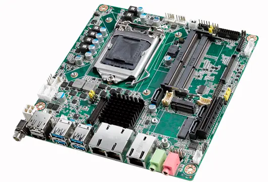
- The SNB-M008 MINI 286 main board is a rugh performance AT compatible main board that provides high speed processing while maintaining full compatibility with the IBM PC/AT main board.
- The SNB-M008 MINI 286 main board arc low power consumption, low board space requirements, high reliability, high integration AT chip set system board.
- Simply stated, you can design a new system or upgrade your existing system with no modifications to eKisting or available components. In fact, your SNB-M008 MINI 286 main board may already have,been installed into a complete system by your dealer.
MAIN FEATURES
The main feature of the SNB-M008 MINI 286 main board as detailed below
- Full IBM PC/AT compatible.
- Used GOLD 286 high-integration ASIC two chip sets.
- Support 80286 16 or 20 Mhz CPU.
- Turbo speed selectable by keyboard or by hardware switch.
- Socket for INTEL 80287 math coprocessor.
- Support 16/20 Mhz, zero wait state up to 20/26 Mhz by chips and CPU.
- Memory socket up to 5MB on board.
- Base memory can use DIP DRAM or RAM MODULE.
- PAGE INTERLEAVED memory controller.
- On board BIOS, capable of adjusting RAM size, shadow ROM BIOS and VIDEO BIOS.
- Support EMS 4.0 driver.
- Real-time clock with rechargeable battery back up CMOS memory for system configuralion data.
- Five 16-biL bus and one 8-bit bus expansion slots.
- 4 layer PCB. A small dimensions (PCB size:22 cn1 x 21 cn1).
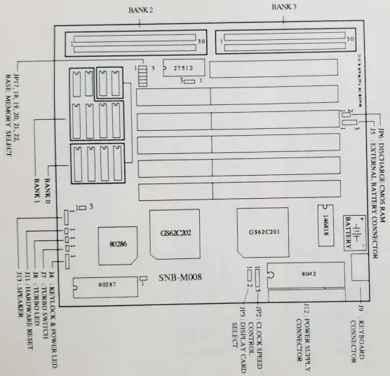
BOARD LAYOUT
Tt1e following shows SNB-M008 MINI 286 main board layout with the positions of the jumper and connectors.
HARDWARE SET UP
The following pages describe the locations and setting of the jumpers.
JUMPER SETTING & DESCRIPTION
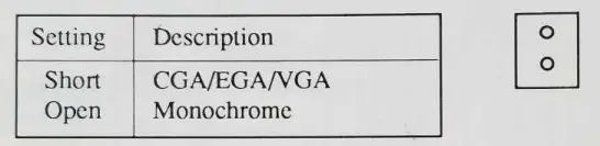
- JP3 : DISPLAY ADAPTER SELECT

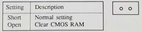
- JP6 : DISCHARGE CMOS RAM

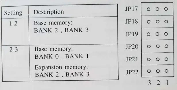
- JP17, JP18, JP19, JP20, JP21, JP22 : BASE MEMORY SELECT

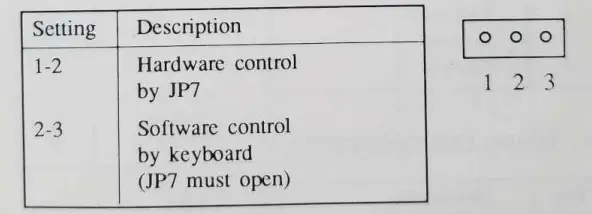
- JP2 : CLOCK SPEED CONTROL
 NOTES: JP1, JP14, JP16 are default factory.
 NOTES: JP1, JP14, JP16 are default factory.
CONNECTORS PINOUT & DESCRIPTION
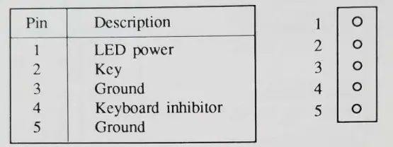
- J4 : K.EYLOCK & POWER LED CONNECTOR

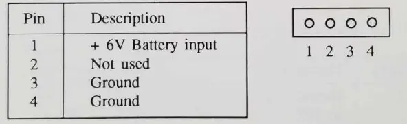
- JS. : EXTERNAL BA’I”l’ERY CONNECTOR

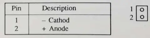
- J8 : TURBO LED CONNECTOR

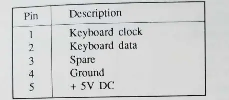
- J9 : KEYBOARD CONNECTOR

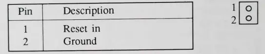
- Jll: HARDWARE RESET CONNECTOR

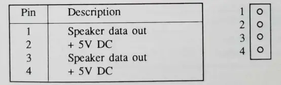
- J 13 : SPEAKER CONNECTOR

- J12 . POWER SUPPLY CONNECTOR
Pin Description 1 2
3
4
5
6
7
8
9
10
11
12
Po wer good + 5V DC
+ 12V DC
– 12Y DC
Ground Ground Ground Ground
– SY DC
+ 5V DC
+ 5V DC
+ SY DC
- J7 : TURBO SWITCH
Setting Description Short Open
Turbo Normal
MEMORY CONFIGURATION
The table below illustrates all the possible memory configurations available using on-board memory. Base memory can use DIP DRAM or RAM MODULE.
- BASE MEMORY: BANK Oj BANK I EXPANSION MEMORY: BANK 2, BANK 3
MODE
TOT AL
MEMORY SIZE
DIP D’ RAM RAM MODULE BANK 0
BANK l
BANK 2
BANK 3
‘
1 512KB 44256 X 4 not used not used not used 2 1MB 44256 X 4 4425 6 X 4 not used not used 3 2MB 44256 X 4 44256 X 4 25 6KB x 2 256KB x 2 4 3MB 44256 X 4 44256 X 4 1MB x 2 not used 5 5MB 44256 X 4 44256 X 4 1MB x 2 lf\lB x 2 - BASE MEMORY: BANK 2 , BANK 3
MODE
TOTAL MEMORY SIZE
DIP DRAM
RAM MODULE BANKO
BANK 1
BANK 2
BANK 3
6
512KB
not used not used 256KB x 2 not usoo 7
1MB
not used not used 256KB x 2 256KB x 2 8 2MB not used not used 1MB x 2 not used 9 2.5MB not used not used 256KB x 2 1MB x 2 10 4MB not used not used 1MB x 2 1MB x 2
BIOS SET UP
This chapter will tell you how to set up the system configuration
(C10S) under the AMf BIOS. If your system has had different BIOS 111stallcd,thcsc procedures will not work. The set up program is co11taincd in the system’s Read Only Memory (ROM), not on a disk like the operating system.
AMI BIOS SYSTEM CONFIGURATION SET UP
The SET UP program lets you specify your system’s configuration of floppy diskette drives, hard disk drives, video display, memory size, BIOS shadow, co-processor wait, fast page rnode, EMS function, date and time. The SET UP program is bulit-in BIOS. Diskette is not necessary for the SET l.W.
RUNNING THE BIOS SETUP PROGRAM
To run CMOS SET UP, follow these procedures:
- Simultaneously press the <CTRL>,<ALT>, and <DEL> keys to reboot the system (or turn the power on if the system is ott). Alter booting the system and testing the memory, in a moment, the following message will appear on the screen: Press <DEL> if you want to run SETUP or DIAGS
- Pleasc Press the <DEL> key (the one that shares the decimal point at the bottom of the numeric keypad). The following menu appears
EXIT FOR BOOT
RUN CMOS SETUP
RUN DIAGNOSTICS
Using the < i > and < J, > keys, highlight RUN CMOS SET UP and press < ENTER > - Follow the instructions to continue until the set up IS finished.
AMI BIOS HARD DISK DRIVES TABLE
| Type | Cyln | Head | WPcom | LZone | Sect | Size | |
| 1 2 3 4 5 6 7 8 9 10 11 12 13 14 15 16 17 18 19 20 2 1 22 23 24 255 26 27 28 29 | 360 | 4 4 6 8 6 4 8 5 15 3 5 7 8 7 0 4 5 7 7 5 7 5 4 7 9 7 l I 7 1() | 128 300 300 512 512 65535 256 65535 65535 65535 65535 65535 128 65535 0 0 300 65535 512 300 300 300 0 0 65535 754 65535 256 655)5 | 305 615 615 940 940 615 511 733 901 820 855 855 319 733 0 663 977 977 1023 732 732 733 336 925 925 754 754 69() 823 | 17 17 17 17 17 17 17 17 17 17 17 17 17 17 0 17 17 17 17 17 17 17 17 17 17 17 17 17 17 | 10 MB 20 MB 1 MB 62 MB 47 MB 20 MB 31 MB 30 MB 112 MB 20 MB 35 MB 50 MB 20 MB 43 MB 0 MB 20 MB 41 MB 57 MB 60 MB 30 MB 43 MB 30 11B 10 N1B 54 118 69 f\11B NtB 0t) “NtR 41 t\10 68 MB | |
| 615 | |||||||
| 615 | |||||||
| 940 | |||||||
| 940 | |||||||
| 615 | |||||||
| 462 | |||||||
| 733 | |||||||
| 900 | |||||||
| 820 | |||||||
| 855 | |||||||
| 855 | |||||||
| 306 | |||||||
| 733 | |||||||
| 000 | |||||||
| 612 | |||||||
| 977 | |||||||
| 977 | |||||||
| 1024 | |||||||
| 733 | |||||||
| 733 | |||||||
| 733 | |||||||
| 306 | |||||||
| 925 | |||||||
| 9 25 | |||||||
| 754 | |||||||
| 754 | |||||||
| ()99 | |||||||
| 823 | |||||||
| T}'(‘)C C)1l n | He ad | WPcom | LZone | Sect | Size | ||||
| I | , | – 3() 91 8 .)) 1 1()24 32 1024 33 10 24 34 612 35 1024 36 10 24 37 615 38 987 39 987 40 820 41 977 42 981 43 830 44 830 45 91’7 46 1224 47<User type> | 7 11 15 5 2 9 8 8 3 7 6 5 5 7 10 15 15 < > | 918 65535 65535 1024 128 65535 512 128 987 987 820 ‘:)77 981 512 65535 65535 65535 < > | 918 | 17 17 17 17 17 17 17 17 17 17 17 17 17 17 17 17 17 | 53 MB 94 MB 128 MB 43 MB 10 MB 77 MB 68 MB 41 MB 25 MB 57 MB 41 MB 41 MB 41 MB 48 MB 69 MB 114 MB 152 MB < > | ||
| 102Lt | |||||||||
| 1024 | |||||||||
| 1024 | |||||||||
| 612 | |||||||||
| 1024 | |||||||||
| 1024 | |||||||||
| 615 | |||||||||
| 987 | |||||||||
| 987 | |||||||||
| 820 | |||||||||
| 977 | |||||||||
| 981 | |||||||||
| 830 | |||||||||
| 830 | |||||||||
| 918 | |||||||||
| 1223 | |||||||||
| < >< | > | ||||||||
EMS DRIVER SET UP
The SNB-M008 MINI 286 main board comes with a EMS driver diskette that contains the file: GS04EMM.SYS. This file must be installed in the CONFlG.SYS file to initialize EMS memory and shadow RAM.
INSTALLING EMS PROCEDURE
To use SNB-M008 MIN1 286 EMS DRIVER SET UP follow this procedure:
- STEP 1. Boot PC system by using DOS and the system will prompt you with A>
- STEP 2. Copy GS04EMM.sys ftle on your DOS diskette.
- STEP 3. Type:
COPY CON CONFIG.SYS <ENTER>
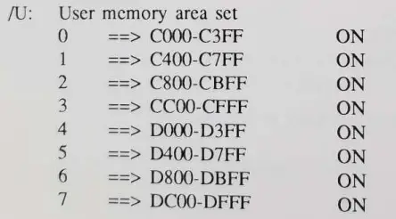
DEVICE=GS04EMM.SYS /E:? /R:? /U:? /X:? <ETTER> “Z <ENTER>
The screen will display as follows:
1 File(s) copied
A>
Where E : EMS page mode.
R : Shadow RAM set.
U : User memory area set.
X : Driver HMA set.
? : GS04EMM.SYS parameters - STEP 4 Reboot your system .
THE GS04EMM.SYS PARAMETERS
There are is described as follows: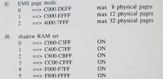
Driver I-IMA set
- () ===> This option will copy the EMS driver to segment location F400 – F7FF. This option wil1 save 16K in the base memory.
- 1 ====> This option will install the EMS driver in the conventional manner. The EMS driver wilJ occupy the system memory.
- 2 ==> This option will install the EMS in the segment
ECOO – EF’FF. This option will save about 16K in the base memory. This is the default.
EXAMPLE:
- DEVICE=GS04EMM.SYS
default:n0 shadow RAM is set, and the driver is copied to segment F400 F7FF. - DEVICE-GSO4EMM.SYS R:0 R:5
This line will set the shadow RAM at location CO00 C3FF (video BIOS) and F800 FFFF (system BIOS). The snke.sys is savedin F400 F7FF. - DEVICE=GS04EMM.SYS /R:0 /R:5 /X:1
Same is the second entry except the driver is loaded in the system memory. - DEVICE-Gso4EMM.SYS /R:0 /R:5 /R:4
This entry will make the atperf benchmark’s ROM accesS ume to appear with less time. This is entry is purely used tor this particular benchmark.


