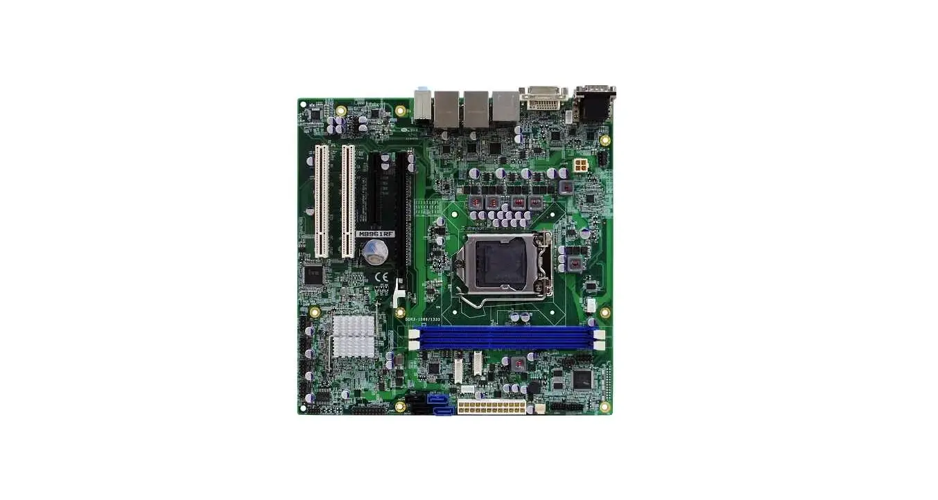
Motherboard B59 Main Board
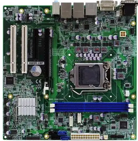
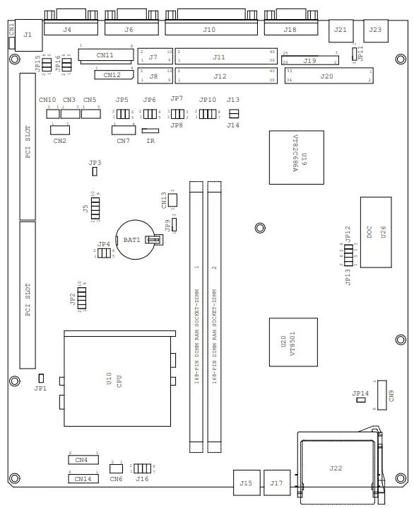
Jumper Location Diagram for “B59 V1.X ” Pentium main board
Memory configuration for “B59 V1.X” main board
- System Memory Configuration
Capacity DIMM 1 DIMM 2 16MB 16MB None 32MB 16MB 16MB 32MB 32MB None 64MB 32MB 32MB 64MB 64MB None 80MB 16MB 64MB 80MB 64MB 16MB 128MB 64MB 64MB 128MB 128MB None 256MB 128MB 128MB - External Cache RAM Configuration.
Capacity SDRAM Type
Quantity Location 256KB 32k x 64 1pcs U15 512KB 64k x 64 1pcs U15
Jumper Setting
In order to set up the correct configuration, here is the description about how to set the jumpers to enable/disable or change functions. All jumpers location please refer to jumper location diagram.
- CPU type selection: J4, J10
CPU JP4 JP10 1-2 3-4 5-6 1-2 3-4 5-6 7-8 Pentium 100MHz Open Open Open Close Open Open Open Pentium 120MHz Close Open Open Open Open Open Open Pentium 133MHz Close Open Open Close Open Open Open Pentium 150MHz Close Close Open Open Open Open Open Pentium 166MHz Close Close Open Close Open Open Open IDT C6 180MHz Open Close Open Open Open Open Open IDT C6 200MHz Open Close Open Close Open Open Open Pentium 200MHz MMX Open Close Open Close Open Open Open Pentium 233MHz MMX Open Open Open Close Open Open Open AMD K6/233MHz(AFR) Open Open Open Close Open Open Open AMD K6/266MHz(AFR) AMD K6-2/266MHz
Close Open Close Close Open Open Open AMD K6-2/300MHz Open Close Open Close Close Close Open AMD K6-2/350MHz Open Open Open Close Close Close Open AMD K6-2/400MHz AMD K6-3/400MHz
Close Open Close Close Close Close Open AMD K6-3/450MHz AMD K6 -2/450MHZ Close Close Close Close Close Close Open AMD K6-2/500MHZ AMD-K6-3/500MHZ
Open Close Close Close Close Close Open - CPU Voltage selection:
Vcore JP2 1-2 3-4 5-6 7-8 9-10 1.5 Open Open Close Open Close 1.6 Open Close Close Open Close 1.7 Open Open Open Close Close 1.8 Open Close Open Close Close 1.9 Open Open Close Close Close 2.0 Open Close Close Close Close 2.1 Close Open Open Open Open 2.2 Open Close Open Open Open 2.3 Close Close Open Open Open 2.4 Open Open Close Open Open 2.5 Close Open Close Open open 2.6 Open Close Close Open Open 2.7 Close Close Close Open Open 2.8 Open Open Open Close Open 2.9 Close Open Open Close Open 3.0 Open Close Open Close Open 3.1 Close Close Open Close Open 3.2 Open Open Close Close Open 3.3 Close Open Close Close Open 3.4 Open Close Close Close Open 3.5 Close Close Close Close Open - CMOS data clean function: JP9
CMOS data JP9 Clean 2-3 Normal (default) 1-2 - Disk On Chip address selection: JP12, JP13
Address JP12 JP13 0 C C 0 0 H – 0 C D F F H 1-2 1-2 0D000H – 0D1FF H 1-2 3-4 0D400H – 0D5FF H 3-4 3-4 0D800H – 0D9FF H 1-2 5-6 0DC00H – 0DDFF H 3-4 5-6 - RS232 Select Jumper: JP5,JP6,JP15,JP16
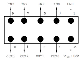
RS232 Select JP5,JP6,JP15,JP16 Normal (default) 1-2 RS232 pin1 use +5V 3-4 RS232 pin1 use +12V 5-6 - Digital I/O (4 Output & 4 Input): J5
- This main board provide the basic digital I/O signal controller, user can develop the program and extra controller to open and sense of the cash drawer based on the digital I/O function on this main board.
PIN ASSIGNMENT 1 GND 6 Out 1 2 VDC +12V 7 IN 2 3 IN 0 8 Out 2 4 Out 0 9 IN 3 5 IN 1 10 Out 3 
- This main board provide the basic digital I/O signal controller, user can develop the program and extra controller to open and sense of the cash drawer based on the digital I/O function on this main board.
Digital output programming
The output is TTL Level. The output signal must be TTL compatible.
| Output | Address | Bit |
| Out 0 | 206 | 0 |
| Out 1 | 206 | 1 |
| Out 2 | 206 | 2 |
| Out 3 | 206 | 3 |
| Example : ( “0” = off “1” =on ) Data 00 = Out 0 and Out 1 = “0” Data 01 = Out 0 = “1” Data 02 = Out 1 = “1” Data 03 = Out 0 and Out 1 = “1” | ||
Digital input programming
The input signal must be TTL compatible.
| Input | Address | Bit |
| IN 0 | 206 | 0 |
| IN 1 | 206 | 1 |
| IN 2 | 206 | 2 |
| IN 3 | 206 | 3 |
| Example : If input 206 is [ 0111], then input 3 is “0”, If input 206 is [0011], then input 3 & 4 are “0” | ||


