![]() H610M Motherboard
H610M Motherboard
User Manual
H610M Motherboard
For more product details, please visit GIGABYTE’s website.
 https://www.gigabyte.com/Motherboard/H610M-HD3P-rev-10?m=ma#kf
To reduce the impacts on global warming, the packaging materials of this product are recyclable and reusable. GIGABYTE works with you to protect the environment.
![]()
Copyright
© 2022 GIGA-BYTE TECHNOLOGY CO., LTD. All rights reserved.
The trademarks mentioned in this manual are legally registered to their respective owners.
Disclaimer
Information in this manual is protected by copyright laws and is the property of GIGABYTE.
Changes to the specifications and features in this manual may be made by GIGABYTE without prior notice. No part of this manual may be reproduced, copied, translated, transmitted, or published in any form or by any means without GIGABYTE’s prior written permission.
- In order to assist in the use of this product, carefully read the User’s Manual.
- For product-related information, check on our website at: https://www.gigabyte.com
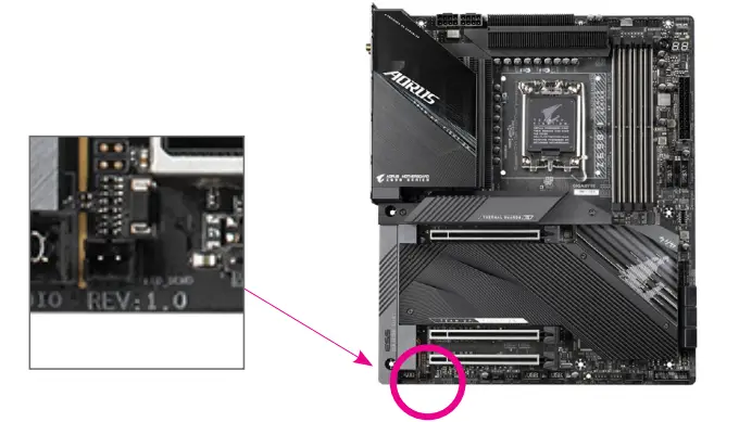
Identifying Your Motherboard Revision
The revision number on your motherboard looks like this: “REV: X.X.” For example, “REV: 1.0” means the revision of the motherboard is 1.0. Check your motherboard revision before updating motherboard BIOS, drivers, or when looking for technical information.
Example:
Chapter 1 Product Introduction
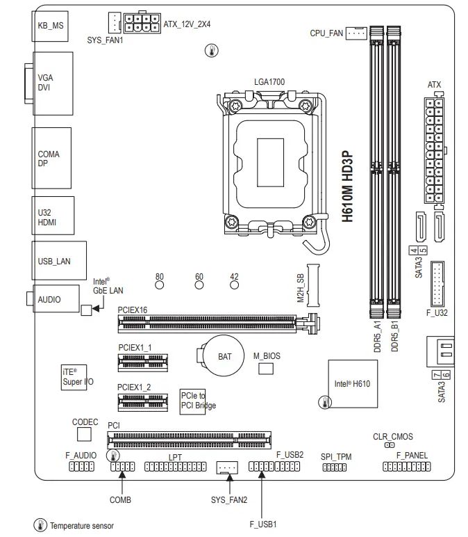
1-1 Motherboard Layout
1-2 Box Contents
- H610M HD3P motherboard
- User’s Manual
- Motherboard driver disc
- Two SATA cables
- I/O Shield
Chapter 2 Hardware Installation
2-1 Installation Precautions
The motherboard contains numerous delicate electronic circuits and components which can become damaged as a result of electrostatic discharge (ESD). Prior to installation, carefully read the user’s manual and follow these procedures:
- Prior to installation, make sure the chassis is suitable for the motherboard.
- Prior to installation, do not remove or break motherboard S/N (Serial Number) sticker or warranty sticker provided by your dealer. These stickers are required for warranty validation.
- Always remove the AC power by unplugging the power cord from the power outlet before installing or removing the motherboard or other hardware components.
- When connecting hardware components to the internal connectors on the motherboard, make sure they are connected tightly and securely.
- When handling the motherboard, avoid touching any metal leads or connectors.
- It is best to wear an electrostatic discharge (ESD) wrist strap when handling electronic components such as a motherboard, CPU or memory. If you do not have an ESD wrist strap, keep your hands dry and first touch a metal object to eliminate static electricity.
- Prior to installing the motherboard, please have it on top of an antistatic pad or within an electrostatic shielding container.
- Before connecting or unplugging the power supply cable from the motherboard, make sure the power supply has been turned off.
- Before turning on the power, make sure the power supply voltage has been set according to the local voltage standard.
- Before using the product, please verify that all cables and power connectors of your hardware components are connected.
- To prevent damage to the motherboard, do not allow screws to come in contact with the motherboard circuit or its components.
- Make sure there are no leftover screws or metal components placed on the motherboard or within the computer casing.
- Do not place the computer system on an uneven surface.
- Do not place the computer system in a high-temperature or wet environment.
- Turning on the computer power during the installation process can lead to damage to system components as well as physical harm to the user.
- If you are uncertain about any installation steps or have a problem related to the use of the product, please consult a certified computer technician.
- If you use an adapter, extension power cable, or power strip, ensure to consult with its installation and/or grounding instructions.
2-2 Product Specifications
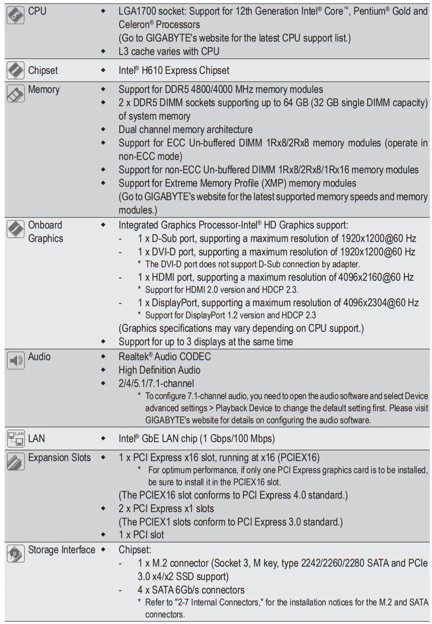
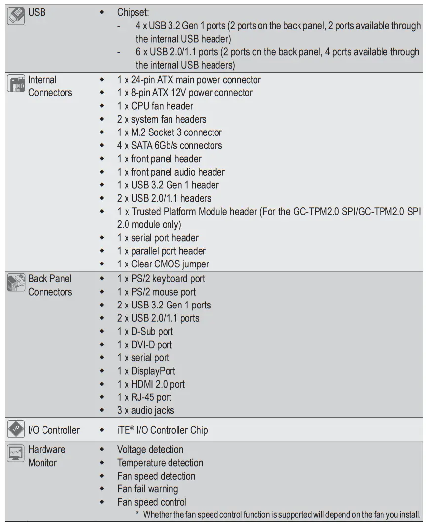
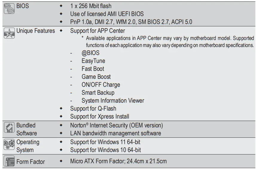
* GIGABYTE reserves the right to make any changes to the product specifications and product-related information without prior notice.
Please visit GIGABYTE’s website for support lists of CPU, memory modules, SSDs, and M.2 devices.
 https://www.gigabyte.com/Motherboard/H610M-HD3P-rev-10?m=dl#support-dl
Please visit the Support\Utility List page on GIGABYTE’s website to download the latest version of apps.
 https://www.gigabyte.com/Support/Utility/Motherboard?m=ut
2-3 Installing the CPU and CPU Cooler![]() Read the following guidelines before you begin to install the CPU:
Read the following guidelines before you begin to install the CPU:
- Make sure that the motherboard supports the CPU.
(Go to GIGABYTE’s website for the latest CPU support list.) - Always turn off the computer and unplug the power cord from the power outlet before installing the CPU to prevent hardware damage.
- Locate the pin one of the CPU. The CPU cannot be inserted if oriented incorrectly. (Or you may locate the notches on both sides of the CPU and alignment keys on the CPU socket.)
- Apply an even and thin layer of thermal grease on the surface of the CPU.
- Do not turn on the computer if the CPU cooler is not installed, otherwise overheating and damage of the CPU may occur.
- Set the CPU host frequency in accordance with the CPU specifications. It is not recommended that the system bus frequency be set beyond hardware specifications since it does not meet the standard requirements for the peripherals. If you wish to set the frequency beyond the standard specifications, please do so according to your hardware specifications including the CPU, graphics card, memory, hard drive, etc.
A. Note the CPU Orientation
Note the alignment keys on the motherboard CPU socket and the notches on the CPU.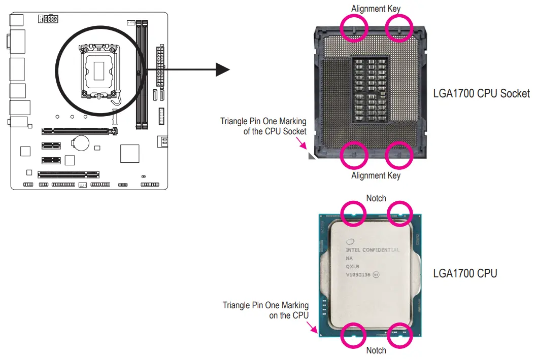
Do not remove the CPU socket cover before inserting the CPU. It may pop off from the load plate automatically after you insert the CPU and close the load plate.
Please visit GIGABYTE’s website for details on hardware installation.
 http://www.gigabyte.com/WebPage/210/quick-guide.html?m=sw
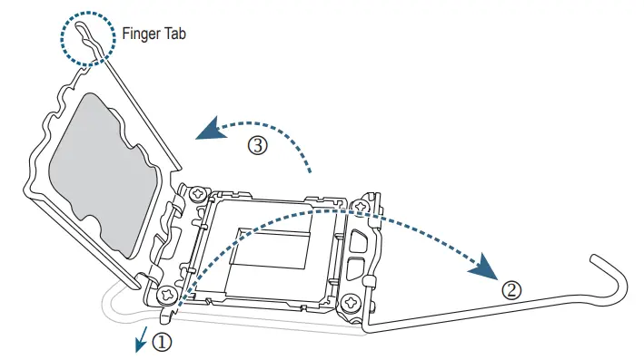
B. Installing the CPU
Follow the steps below to correctly install the CPU into the motherboard CPU socket.
- Gently press the CPU socket lever handle down and away from the socket.
- Completely lift up the CPU socket locking lever.
- Use the finger tab on the side of the metal load plate to lift open the metal load plate with the plastic protective cover attached toit.

Hold the CPU with your fingers by the edges.
Align the CPU pin one marking (triangle) with the pin one corner of the CPU socket (or you may align the CPU notches with the socket alignment keys) and gently insert the CPU into position.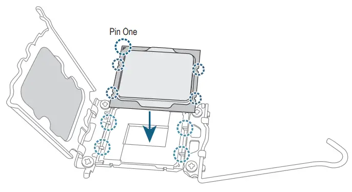
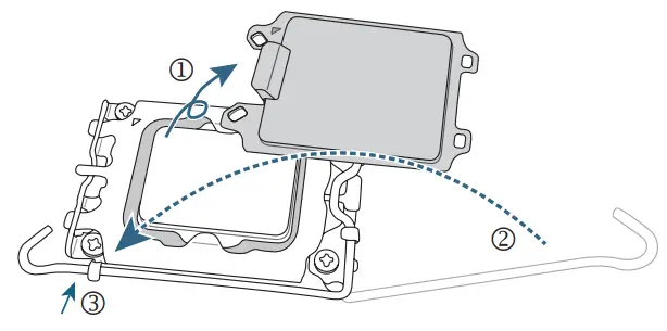
Make sure the CPU is properly installed and then close the load plate. The plastic protective cover will pop off, just remove it. Secure the lever under its retention tab to complete the installation of the CPU.
* Always replace the plastic protective cover when the CPU is not installed to protect the CPU socket.
![]() Do not force to engage the CPU socket locking lever when the CPU is not installed correctly as this would damage the CPU and CPU socket.
Do not force to engage the CPU socket locking lever when the CPU is not installed correctly as this would damage the CPU and CPU socket.
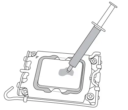
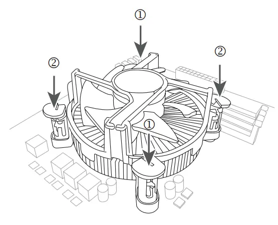
C. Installing the CPU Cooler
Be sure to install the CPU cooler after installing the CPU. (Actual installation process may differ depending the CPU cooler to be used. Refer to the user’s manual for your CPU cooler.)
- Apply an even and thin layer of thermal grease on the surface of the installed CPU.

- Place the cooler atop the CPU, aligning the four push pins through the pin holes on the motherboard. Push down on the push pins diagonally.

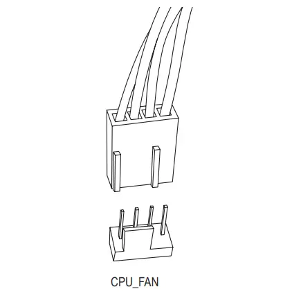
- Finally, attach the power connector of the CPU cooler to the CPU fan header (CPU_FAN) on the motherboard.

2-4 Installing the Memory![]() Read the following guidelines before you begin to install the memory:
Read the following guidelines before you begin to install the memory:
- Make sure that the motherboard supports the memory. It is recommended that memory of the same capacity, brand, speed, and chips be used. (Go to GIGABYTE’s website for the latest supported memory speeds and memory modules.)
- Always turn off the computer and unplug the power cord from the power outlet before installing the memory to prevent hardware damage.
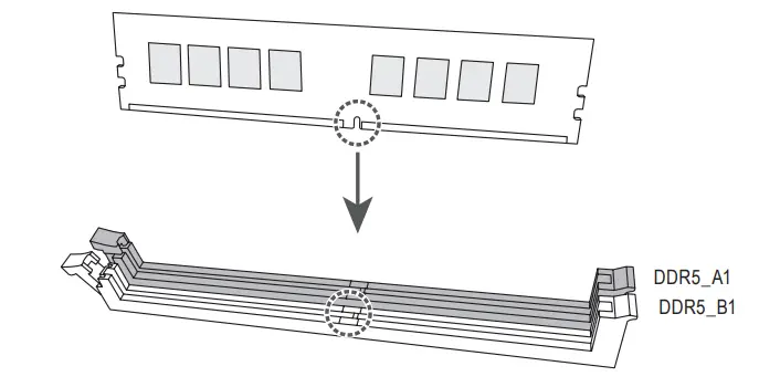
- Memory modules have a foolproof design. A memory module can be installed in only one direction. If you are unable to insert the memory, switch the direction.
Dual Channel Memory Configuration
This motherboard provides two memory sockets and supports Dual Channel Technology. After the memory is installed, the BIOS will automatically detect the specifications and capacity of the memory. Enabling Dual Channel memory mode will double the original memory bandwidth.
The four memory sockets are divided into two channels and each channel has two memory sockets as following:
- Channel A: DDR5_A1
- Channel B: DDR5_B1
Due to CPU limitations, read the following guidelines before installing the memory in Dual Channel mode.
- Dual Channel mode cannot be enabled if only one memory module is installed.
- When enabling Dual Channel mode with two memory modules, it is recommended that memory of the same capacity, brand, speed, and chips be used.

2-5 Installing an Expansion Card
Read the following guidelines before you begin to install an expansion card:
- Make sure the motherboard supports the expansion card. Carefully read the manual that came with your expansion card.
- Always turn off the computer and unplug the power cord from the power outlet before installing an expansion card to prevent hardware damage.
![]() Follow the steps below to correctly install your expansion card in the expansion slot.
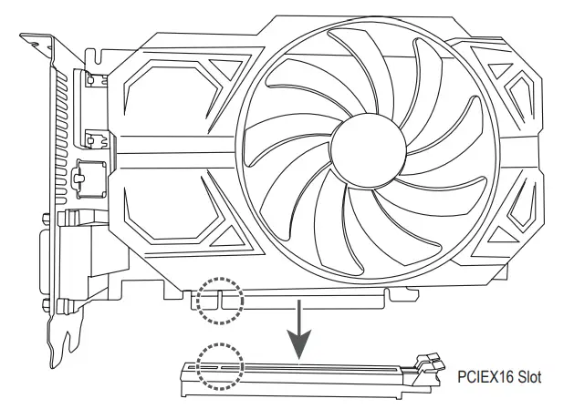
Follow the steps below to correctly install your expansion card in the expansion slot.
- Locate an expansion slot that supports your card. Remove the metal slot cover from the chassis back panel.
- Align the card with the slot, and press down on the card until it is fully seated in the slot.
- Make sure the metal contacts on the card are completely inserted into the slot.
- Secure the card’s metal bracket to the chassis back panel with a screw.
- After installing all expansion cards, replace the chassis cover(s).
- Turn on your computer. If necessary, go to BIOS Setup to make any required BIOS changes for your expansion card(s).
- Install the driver provided with the expansion card in your operating system.
2-6 Back Panel Connectors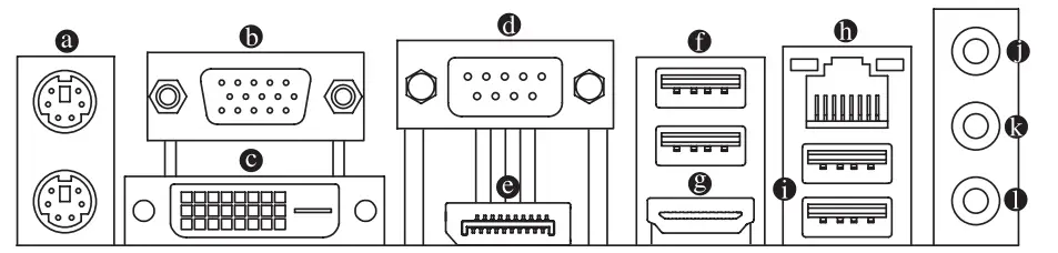
PS/2 Keyboard and PS/2 Mouse Port
Use the upper port (green) to connect a PS/2 mouse and the lower port (purple) to connect a PS/2 keyboard.
D-Sub Port
The D-Sub port supports a 15-pin D-Sub connector and supports a maximum resolution of 1920×1200@60 Hz (the actual resolutions supported depend on the monitor being used). Connect a monitor that supports D-Sub connection to this port.
DVI-D Port
(Note) The DVI-D port conforms to the DVI-D specification and supports a maximum resolution of 1920×1200@60 Hz (the actual resolutions supported depend on the monitor being used). Connect a monitor that supports DVI-D connection to this port.
Serial Port
Use the serial port to connect devices such as a mouse, modem or other peripherals.
DisplayPort
DisplayPort delivers high quality digital imaging and audio, supporting bi-directional audio transmission.
DisplayPort can support HDCP 2.3 content protection mechanisms. You can use this port to connect your DisplayPort-supported monitor. Note: The DisplayPort Technology can support a maximum resolution of 4096×2304@60 Hz but the actual resolutions supported depend on the monitor being used.
USB 3.2 Gen 1 Port
The USB 3.2 Gen 1 port supports the USB 3.2 Gen 1 specification and is compatible to the USB 2.0 specification. Use this port for USB devices.
HDMI 2.0 Port The HDMI port supports HDCP 2.3 and Dolby TrueHD and DTS HD Master Audio formats. It also supports up to 192KHz/24bit 7.1- channel LPCM audio output. You can use this port to connect your HDMI-supported monitor. The maximum supported resolution is 4096×2160@60 Hz, but the actual resolutions supported are dependent on the monitor being used.
- To set up a triple-display configuration,you must install motherboard drivers in the operating system first
- After installing the HDMI/DisplayPort device, make sure to set the default sound playback device to HDMI/DisplayPort. (The item name may differ depending on your operating system.)
RJ-45 LAN Port
The Gigabit Ethernet LAN port provides Internet connection at up to 1 Gbps data rate. The following describes the states of the LAN port LEDs.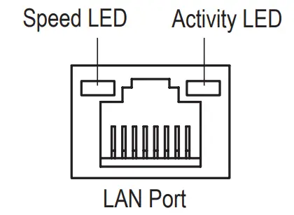
Speed LED:
| State | Description |
| Orange | 1 Gbps data rate |
| Green | 100 Mbps data rate |
| Off | 10 Mbps data rate |
Activity LED:
| State | Description |
| Blinking | Data transmission or receiving is occurring |
| On | No data transmission or receiving is occurring |
(Note) The DVI-D port does not support D-Sub connection by adapter.
- USB 2.0/1.1 Port
The USB port supports the USB 2.0/1.1 specification. Use this port for USB devices. - Line In/Rear Speaker Out (Blue)
The line in jack. Use this audio jack for line in devices such as an optical drive, walkman, etc. - Line Out/Front Speaker Out (Green)
The line out jack. - Mic In/Center/Subwoofer Speaker Out (Pink)
The Mic in jack.
Audio Jack Configurations:
| Jack | Headphone/2-channel | 4-channel | 5.1-channel | 7.1-channel |
| Line In/Rear Speaker Out | ||||
| 0 Line Out/Front Speaker Out | ||||
| Mic In/Center/Subwoofer Speaker Out | ||||
| Front Panel Line Out/Side Speaker Out |
![]()
- You can change the functionality of an audio jack using the audio software.
- To configure 7.1-channel audio, you need to open the audio software and select Device advanced settings > Playback Device to change the default setting first.
- When removing the cable connected to a back panel connector, first remove the cable from your device and then remove it from the motherboard.

- When removing the cable, pull it straight out from the connector. Do not rock it side to side to prevent an electrical short inside the cable connector.
2-7 Internal Connectors
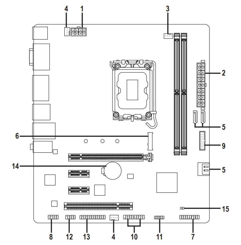
| 1) ATX_12V_2X4 | 9) F_U32 |
| 2) ATX | 10) F_USB1/F_USB2 |
| 3) CPU_FAN | 11) SPI_TPM |
| 4) SYS_FAN1/2 | 12) COMB |
| 5) SATA3 4/5/6/7 | 13) LPT |
| 6) M2H_SB | 14) BAT |
| 7) F_PANEL | 15) CLR_CMOS |
| 8) F_AUDIO |
Read the following guidelines before connecting external devices:
- First make sure your devices are compliant with the connectors you wish to connect.
- Before installing the devices, be sure to turn off the devices and your computer. Unplug the power cord from the power outlet to prevent damage to the devices.
- After installing the device and before turning on the computer, make sure the device cable has been securely attached to the connector on the motherboard.
1/2) ATX_12V_2X4/ATX (2×4, 12V Power Connector and 2×12 Main Power Connector)
With the use of the power connector, the power supply can supply enough stable power to all the components on the motherboard. Before connecting the power connector, first make sure the power supply is turned off and all devices are properly installed. The power connector possesses a foolproof design. Connect the power supply cable to the power connector in the correct orientation.
The 12V power connector mainly supplies power to the CPU. If the 12V power connector is not connected, the computer will not start.![]() To meet expansion requirements, it is recommended that a power supply that can withstand high power consumption be used (500W or greater). If a power supply is used that does not provide the required power, the result can lead to an unstable or unbootable system.
To meet expansion requirements, it is recommended that a power supply that can withstand high power consumption be used (500W or greater). If a power supply is used that does not provide the required power, the result can lead to an unstable or unbootable system.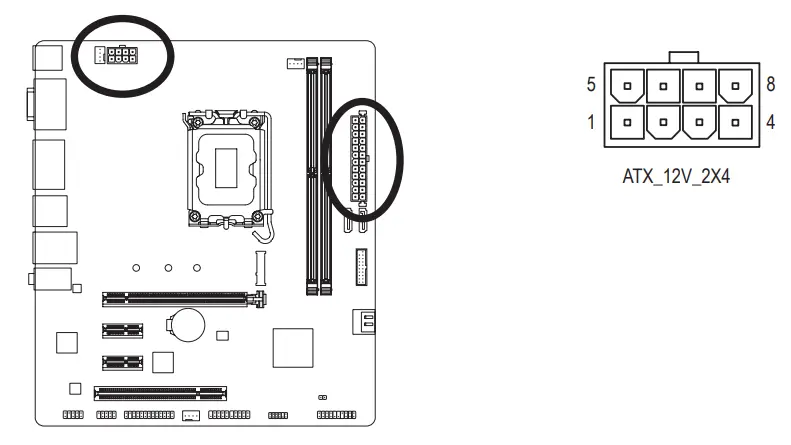
| Pin No. | Definition | Pin No. | Definition |
| 1 | GND (Only for 2×4-pin 12V) | 5 | +12V (Only for 2×4-pin 12V) |
| 2 | GND (Only for 2×4-pin 12V) | 6 | +12V (Only for 2×4-pin 12V) |
| 3 | GND | 7 | +12V |
| 4 | GND | 8 | +12V |
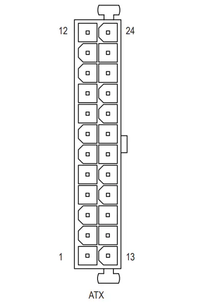
ATX:
| Pin No. | Definition | Pin No. | Definition |
| 1 | 3.3V | 13 | 3.3V |
| 2 | 3.3V | 14 | -12V |
| 3 | GND | 15 | GND |
| 4 | +5V | 16 | PS_ON (soft On/Off) |
| 5 | GND | 17 | GND |
| 6 | +5V | 18 | GND |
| 7 | GND | 19 | GND |
| 8 | Power Good | 20 | NC |
| 9 | 5VSB (stand by +5V) | 21 | +5V |
| 10 | +12V | 22 | +5V |
| 11 | +12V (Only for 2×12-pin ATX) | 23 | +5V (Only for 2×12-pin ATX) |
| 12 | 3.3V (Only for 2×12-pin ATX) | 24 | GND (Only for 2×12-pin ATX) |
CPU_FAN/SYS_FAN1/2 (Fan Headers)
All fan headers on this motherboard are 4-pin. Most fan headers possess a foolproof insertion design.
When connecting a fan cable, be sure to connect it in the correct orientation (the black connector wire is the ground wire). The speed control function requires the use of a fan with fan speed control design. For optimum heat dissipation, it is recommended that a system fan be installed inside the chassis.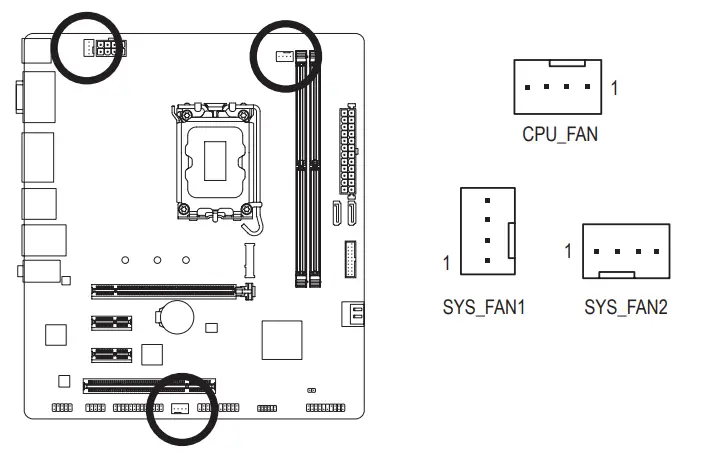
| Pin No. | Definition |
| 1 | GND |
| 2 | Voltage Speed Control |
| 3 | Sense |
| 4 | PWM Speed Control |
- Be sure to connect fan cables to the fan headers to prevent your CPU and system from overheating. Overheating may result in damage to the CPU or the system may hang.
- These fan headers are not configuration jumper blocks. Do not place a jumper cap on the headers.
SATA3 4/5/6/7 (SATA 6Gb/s Connectors)
The SATA connectors conform to SATA 6Gb/s standard and are compatible with SATA 3Gb/s and SATA 1.5Gb/s standard. Each SATA connector supports a single SATA device.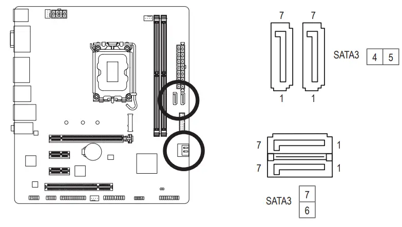
| Pin No. | Definition |
| 1 | GND |
| 2 | TXP |
| 3 | TXN |
| 4 | GND |
| 5 | RXN |
| 6 | RXP |
| 7 | GND |
![]() To enable hot-plugging for the SATA ports, please navigate to the “BIOS Setup” page of GIGABYTE’s website and search for “SATA Configuration” for more information.
To enable hot-plugging for the SATA ports, please navigate to the “BIOS Setup” page of GIGABYTE’s website and search for “SATA Configuration” for more information.
M2H_SB (M.2 Socket 3 Connectors)
The M.2 connector supports M.2 SATA SSDs or M.2 PCIe SSDs.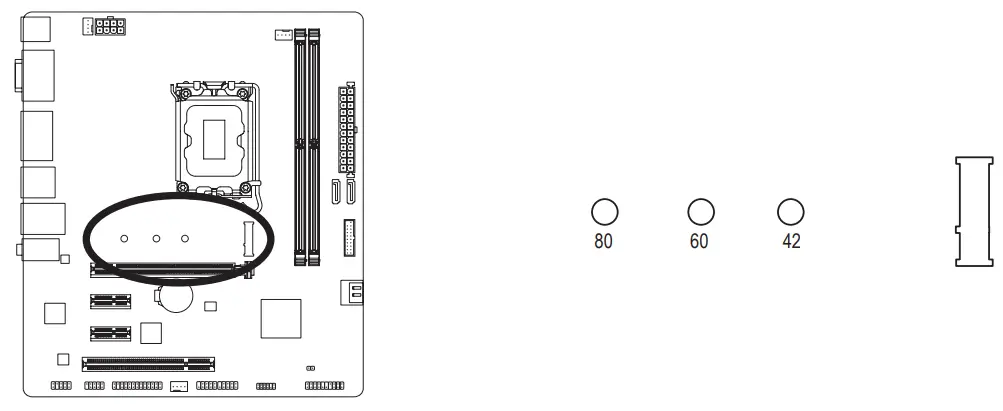
Follow the steps below to correctly install an M.2 SSD in the M.2 connector.
Step 1:
Locate the proper mounting hole for the M.2 SSD to be installed and then install the mounting clip first.
Step 2:
Slide the M.2 SSD into the connector at an angle.
Step 3:
Press the M.2 SSD down and then secure it by pressing the clip pin into the mounting hole.
* Types of M.2 SSD supported by the M.2 connector:
| M.2 PCIe x4 SSD | M.2 PCIe x2 SSD | M.2 SATA SSD | |
| M2H_SB |
Installation Notices for the M.2 and SATA Connectors:
The availability of the SATA connectors may be affected by the type of device installed in the M.2 sockets.
The M2H_SB connector shares bandwidth with the SATA3 7 connector. Refer to the following table for details.
F_PANEL (Front Panel Header)
Connect the power switch, reset switch, speaker, chassis intrusion switch/sensor and system status indicator on the chassis to this header according to the pin assignments below. Note the positive and negative pins before connecting the cables.
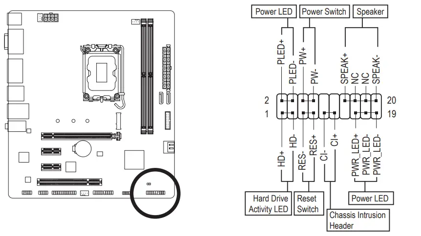 PLED/PWR_LED (Power LED):
| System Status | LED |
| S0 | On |
| S3/S4/S5 | Off |
Connects to the power status indicator on the chassis front panel. The LED is on when the system is operating. The LED is off when the system is in S3/S4 sleep state or powered off (S5).
- PW (Power Switch):
Connects to the power switch on the chassis front panel. You may configure the way to turn off your system using the power switch (please navigate to the “BIOS Setup” page of GIGABYTE’s website and search for “Soft-Off by PWR-BTTN” for more information). - SPEAK (Speaker):
Connects to the speaker on the chassis front panel. The system reports system startup status by issuing a beep code. One single short beep will be heard if no problem is detected at system startup. - HD (Hard Drive Activity LED):
Connects to the hard drive activity LED on the chassis front panel. The LED is on when the hard drive is reading or writing data. - RES (Reset Switch):
Connects to the reset switch on the chassis front panel. Press the reset switch to restart the computer if the computer freezes and fails to perform a normal restart. - CI (Chassis Intrusion Header):
Connects to the chassis intrusion switch/sensor on the chassis that can detect if the chassis cover has been removed. This function requires a chassis with a chassis intrusion switch/sensor. - NC: No connection.
The front panel design may differ by chassis. A front panel module mainly consists of power switch, reset switch, power LED, hard drive activity LED, speaker and etc. When connecting your chassis front panel module to this header, make sure the wire assignments and the pin assignments are matched correctly.
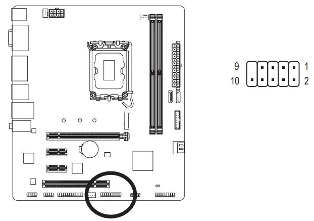
F_AUDIO (Front Panel Audio Header)
The front panel audio header supports High Definition audio (HD). You may connect your chassis front panel audio module to this header. Make sure the wire assignments of the module connector match the pin assignments of the motherboard header. Incorrect connection between the module connector and the motherboard header will make the device unable to work or even damage it.
| Pin No. | Definition |
| 1 | MIC L |
| 2 | GND |
| 3 | MIC R |
| 4 | NC |
| 5 | Head Phone R |
| 6 | MIC Detection |
| 7 | SENSE_SEND |
| 8 | No Pin |
| 9 | Head Phone L |
| 10 | Head Phone Detection |
Some chassis provide a front panel audio module that has separated connectors on each wire instead of a single plug. For information about connecting the front panel audio module that has different wire assignments, please contact the chassis manufacturer.
F_U32 (USB 3.2 Gen 1 Header)
The header conforms to USB 3.2 Gen 1 and USB 2.0 specification and can provide two USB ports. For purchasing the optional 3.5″ front panel that provides two USB 3.2 Gen 1 ports, please contact the local dealer.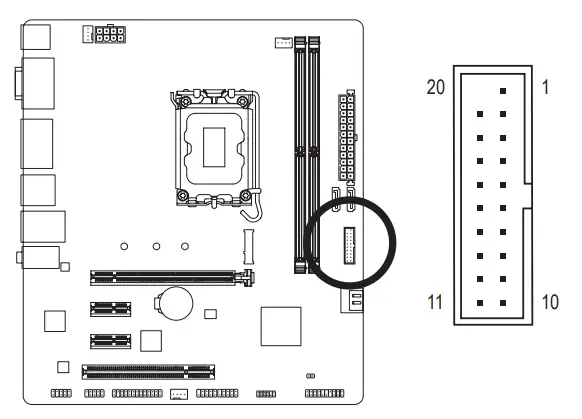
| Pin No. | Definition | Pin No. | Definition |
| 1 | VBUS | 11 | D2+ |
| 2 | SSRX1- | 12 | D2- |
| 3 | SSRX1+ | 13 | GND |
| 4 | GND | 14 | SSTX2+ |
| 5 | SSTX1- | 15 | SSTX2- |
| 6 | SSTX1+ | 16 | GND |
| 7 | GND | 17 | SSRX2+ |
| 8 | D1- | 18 | SSRX2- |
| 9 | D1+ | 19 | VBUS |
| 10 | NC | 20 | No Pin |
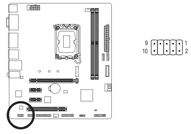
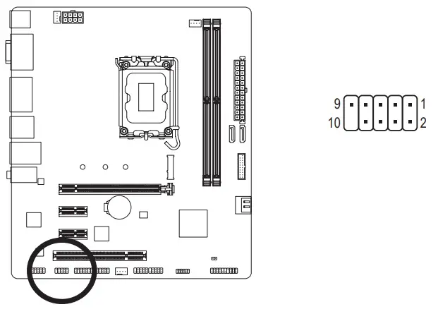
F_USB1/F_USB2 (USB 2.0/1.1 Headers)
The headers conform to USB 2.0/1.1 specification. Each USB header can provide two USB ports via an optional USB bracket. For purchasing the optional USB bracket, please contact the local dealer.
| Pin No. | Definition |
| 1 | Power (5V) |
| 2 | Power (5V) |
| 3 | USB DX- |
| 4 | USB DY- |
| 5 | USB DX+ |
| 6 | USB DY+ |
| 7 | GND |
| 8 | GND |
| 9 | No Pin |
| 10 | NC |
![]()
- Do not plug the IEEE 1394 bracket (2×5-pin) cable into the USB 2.0/1.1 header.
- Prior to installing the USB bracket, be sure to turn off your computer and unplug the power cord from the power outlet to prevent damage to the USB bracket.
SPI_TPM (Trusted Platform Module Header)
You may connect an SPI TPM (Trusted Platform Module) to this header.
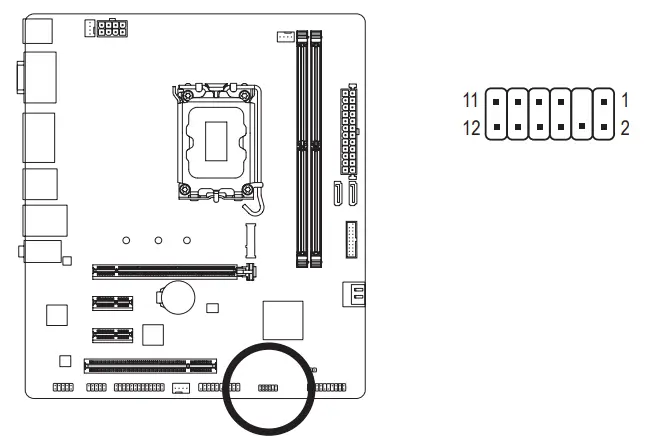
| Pin No. | Definition |
| 1 | Data Output |
| 2 | Power (3.3V) |
| 3 | No Pin |
| 4 | NC |
| 5 | Data Input |
| 6 | CLK |
| 7 | Chip Select |
| 8 | GND |
| 9 | IRQ |
| 10 | NC |
| 11 | NC |
| 12 | RST |
COMB (Serial Port Header)
The COM header can provide one serial port via an optional COM port cable. For purchasing the optional COM port cable, please contact the local dealer.
| Pin No. | Definition |
| 1 | NDCD- |
| 2 | NSIN |
| 3 | NSOUT |
| 4 | NDTR- |
| 5 | GND |
| 6 | NDSR- |
| 7 | NRTS |
| 8 | NCTS- |
| 9 | NRI- |
| 10 | No Pin |
LPT (Parallel Port Header)
The LPT header can provide one parallel port via an optional LPT port cable. For purchasing the optional LPT port cable, please contact the local dealer.
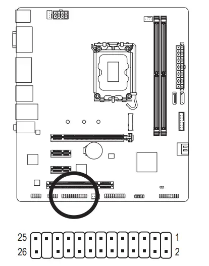
| Pin No. | Definition | Pin No. | Definition |
| 1 | STB- | 14 | GND |
| 2 | AFD- | 15 | PD6 |
| 3 | PDO | 16 | GND |
| 4 | ERR- | 17 | PD7 |
| 5 | PD1 | 18 | GND |
| 6 | INIT- | 19 | ACK- |
| 7 | PD2 | 20 | GND |
| 8 | SLIN- | 21 | BUSY |
| 9 | PD3 | 22 | GND |
| 10 | GND | 23 | PE |
| 11 | PD4 | 24 | No Pin |
| 12 | GND | 25 | SLCT |
| 13 | PD5 | 26 | GND |
BAT (Battery)
The battery provides power to keep the values (such as BIOS configurations, date, and time information) in the CMOS when the computer is turned off. Replace the battery when the battery voltage drops to a low level, or the CMOS values may not be accurate or may be lost.
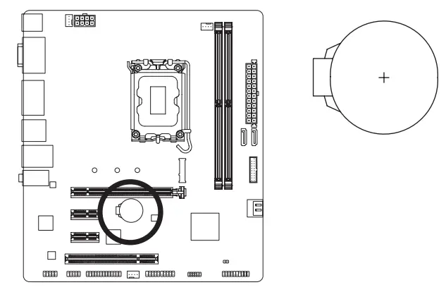
You may clear the CMOS values by removing the battery:
- Turn off your computer and unplug the power cord.
- Gently remove the battery from the battery holder and wait for one minute. (Or use a metal object like a screwdriver to touch the positive and negative terminals of the battery holder, making them short for 5 seconds.)
- Replace the battery.
- Plug in the power cord and restart your computer.
• Always turn off your computer and unplug the power cord before replacing the battery.
• Replace the battery with an equivalent one. Damage to your devices may occur if the battery is replaced with an incorrect model.
• Contact the place of purchase or local dealer if you are not able to replace the battery by yourself or uncertain about the battery model.
• When installing the battery, note the orientation of the positive side (+) and the negative side (-) of the battery (the positive side should face up).
• Used batteries must be handled in accordance with local environmental regulations.
CLR_CMOS (Clear CMOS Jumper)
Use this jumper to clear the BIOS configuration and reset the CMOS values to factory defaults. To clear the CMOS values, use a metal object like a screwdriver to touch the two pins for a few seconds.
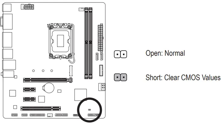
- Always turn off your computer and unplug the power cord from the power outlet before clearing the CMOS values.
- After system restart, go to BIOS Setup to load factory defaults (select Load Optimized Defaults) or manually configure the BIOS settings (please navigate to the “BIOS Setup” page of GIGABYTE’s website for more information).
Chapter 3 BIOS Setup
BIOS (Basic Input and Output System) records hardware parameters of the system in the CMOS on the motherboard. Its major functions include conducting the Power-On Self-Test (POST) during system startup, saving system parameters and loading operating system, etc. BIOS includes a BIOS Setup program that allows the user to modify basic system configuration settings or to activate certain system features.
When the power is turned off, the battery on the motherboard supplies the necessary power to the CMOS to keep the configuration values in the CMOS.
To access the BIOS Setup program, press the <Delete> key during the POST when the power is turned on.
To upgrade the BIOS, use either the GIGABYTE Q-Flash or @BIOS utility.
- Q-Flash allows the user to quickly and easily upgrade or back up BIOS without entering the operating system.
- @BIOS is a Windows-based utility that searches and downloads the latest version of BIOS from the Internet and updates the BIOS.
For instructions on using the Q-Flash and @BIOS utilities, please navigate to the “Unique Features” page of GIGABYTE’s website and search for “BIOS Update Utilities.” - Because BIOS flashing is potentially risky, if you do not encounter problems using the current version of BIOS, it is recommended that you not flash the BIOS. To flash the BIOS, do it with caution. Inadequate BIOS flashing may result in system malfunction.
- It is recommended that you not alter the default settings (unless you need to) to prevent system instability or other unexpected results. Inadequately altering the settings may result in system’s failure to boot. If this occurs, try to clear the CMOS values and reset the board to default values.
- Refer to the introductions of the battery/clear CMOS jumper in Chapter 2 or navigate to the “BIOS Setup” page of GIGABYTE’s website and search for “Load Optimized Defaults” for how to clear the CMOS values.
Startup Screen:
The following startup Logo screen will appear when the computer boots.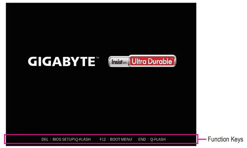
Function Keys:
<DEL>: BIOS SETUP\Q-FLASH
Press the <Delete> key to enter BIOS Setup or to access the Q-Flash utility in BIOS Setup. <F12>: BOOT MENU
Boot Menu allows you to set the first boot device without entering BIOS Setup. In Boot Menu, use the up arrow key <h> or the down arrow key <i> to select the first boot device, then press <Enter> to accept.
The system will boot from the device immediately.
Note: The setting in Boot Menu is effective for one time only. After system restart, the device boot order will still be based on BIOS Setup settings.
<END>: Q-FLASH
Press the <End> key to access the Q-Flash utility directly without having to enter BIOS Setup first.
Chapter 4 Installing the Operating System and Drivers
4-1 Operating System Installation
With the correct BIOS settings, you are ready to install the operating system.
4-2 Drivers Installation![]() After installing the operating system, insert the motherboard driver disc into your optical drive. Click on the message “Tap to choose what happens with this disc” on the top-right corner of the screen and select “Run Run.exe.” (Or go to My Computer, double-click the optical drive and execute the Run.exe program.)
After installing the operating system, insert the motherboard driver disc into your optical drive. Click on the message “Tap to choose what happens with this disc” on the top-right corner of the screen and select “Run Run.exe.” (Or go to My Computer, double-click the optical drive and execute the Run.exe program.)
“Xpress Install” will automatically scan your system and then list all of the drivers that are recommended to install. You can click the Xpress Install button and “Xpress Install” will install all of the selected drivers. Or click the arrow ![]() icon to individually install the drivers you need.=
icon to individually install the drivers you need.=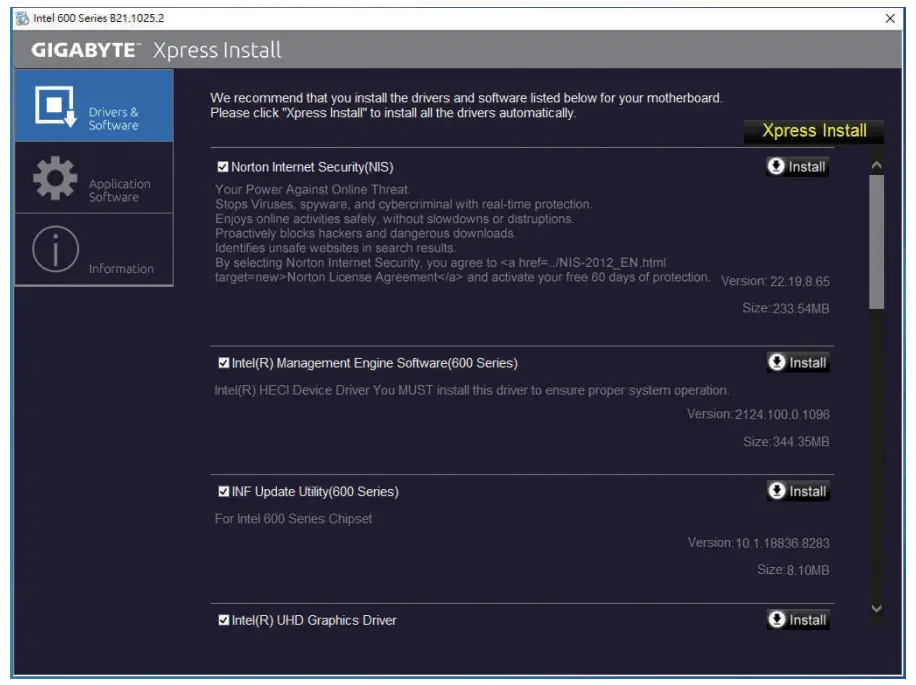
Regulatory Notices
United States of America, Federal Communications Commission Statement
Supplier’s Declaration of Conformity
47 CFR § 2.1077 Compliance Information
Product Name: Motherboard
Trade Name: GIGABYTE
Model Number: H610M HD3P
Responsible Party – U.S. Contact Information: G.B.T. Inc.
Address: 17358 Railroad street, City Of Industry, CA91748
Tel.: 1-626-854-9338
Internet contact information: https://www.gigabyte.com
FCC Compliance Statement:
This device complies with Part 15 of the FCC Rules, Subpart B, Unintentional Radiators.
Operation is subject to the following two conditions: (1) This device may not cause harmful interference, and (2) this device must accept any interference received, including interference that may cause undesired operation.
This equipment has been tested and found to comply with the limits for a Class B digital device, pursuant to Part 15 of the FCC Rules. These limits are designed to provide reasonable protection against harmful interference in a residential installation. This equipment generates, uses and can radiate radio frequency energy and, if not installed and used in accordance with manufacturer’s instructions, may cause harmful interference to radio communications. However, there is no guarantee that interference will not occur in a particular installation. If this equipment does cause harmful interference to radio or television reception, which can be determined by turning the equipment off and on, the user is encouraged to try to correct the interference by one or more of the following measures:
- Reorient or relocate the receiving antenna.
- Increase the separation between the equipment and receiver.
- Connect the equipment to an outlet on a circuit different from that to which the receiver is connected.
- Consult the dealer or an experienced radio/TV technician for help.
Canadian Department of Communications Statement
This digital apparatus does not exceed the Class B limits for radio noise emissions from digital apparatus set out in the Radio Interference Regulations of the Canadian Department of Communications. This class B digital apparatus complies with Canadian ICES-003.
European Union (EU) CE Declaration of Conformity
This device complies with the following directives: Electromagnetic
Compatibility Directive 2014/30/EU, Low-voltage Directive 2014/35/EU, RoHS directive (recast) 2011/65/EU & the 2015/863 Statement.
This product has been tested and found to comply with all essential requirements of the Directives.
European Union (EU) RoHS (recast) Directive 2011/65/EU & the European Commission Delegated Directive (EU) 2015/863 Statement GIGABYTE products have not intended to add and safe from hazardous substances (Cd, Pb, Hg, Cr+6, PBDE, PBB, DEHP, BBP, DBP and DIBP).
The parts and components have been carefully selected to meet RoHS requirement. Moreover, we at GIGABYTE are continuing our efforts to develop products that do not use internationally banned toxic chemicals.
European Union (EU) Community Waste Electrical & Electronic Equipment (WEEE) Directive Statement
GIGABYTE will fulfill the national laws as interpreted from the 2012/19/EU WEEE (Waste Electrical and Electronic Equipment) (recast) directive.
The WEEE Directive specifies the treatment, collection, recycling and disposal of electric and electronic devices and their components. Under the Directive, used equipment must be marked, collected separately, and disposed of properly.
WEEE Symbol Statement![]() The symbol shown below is on the product or on its packaging, which indicates that this product must not be disposed of with other waste. Instead, the device should be taken to the waste collection centers for activation of the treatment, collection, recycling and disposal procedure.
The symbol shown below is on the product or on its packaging, which indicates that this product must not be disposed of with other waste. Instead, the device should be taken to the waste collection centers for activation of the treatment, collection, recycling and disposal procedure.
For more information about where you can drop off your waste equipment for recycling, please contact your local government office, your household waste disposal service or where you purchased the product for details of environmentally safe recycling.
End of Life Directives-Recycling![]() The symbol shown below is on the product or on its packaging, which indicates that this product must not be disposed of with other waste. Instead, the device should be taken to the waste collection centers for activation of the treatment, collection, recycling and disposal procedure.
The symbol shown below is on the product or on its packaging, which indicates that this product must not be disposed of with other waste. Instead, the device should be taken to the waste collection centers for activation of the treatment, collection, recycling and disposal procedure.
Contact Us
GIGA-BYTE TECHNOLOGY CO., LTD.
Address: No.6, Baoqiang Rd., Xindian Dist., New Taipei City 231, Taiwan
TEL: +886-2-8912-4000, FAX: +886-2-8912-4005
Tech. and Non-Tech. Support (Sales/Marketing) : https://esupport.gigabyte.com
WEB address (English): https://www.gigabyte.com
WEB address (Chinese): https://www.gigabyte.com/tw
GIGABYTE eSupport
To submit a technical or non-technical (Sales/Marketing) question, please link to: https://esupport.gigabyte.com