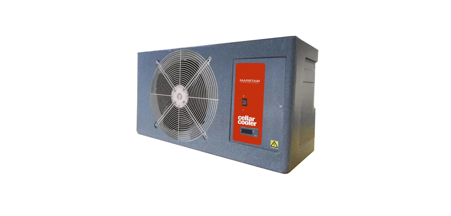

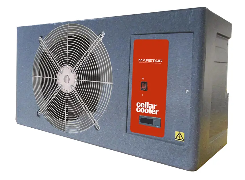
MARSTAIR CKC20PD R407C Outdoor Unit Low Temp Pump
GENERAL
- TEV Ltd recommend that personnel working on this equipment be skilled and fully conversant with the appropriate Air Conditioning, Refrigeration and Electrical practices and have sound knowledge of current Industrial Safe Working practices.
- CXE models are electromechanical / Electronic control units that use R407C refrigerant; they provide cooling within the range of 2.8 – 8.5 kW. These units are matched with CKC pump down outdoor units to complete a system.
- CXE Pump Down units are fitted with an expansion assembly and solenoid valve These units must be ran on a liquid line and matched with the Marstair CKC Pump Down units which are fitted with a liquid receiver.
- These units contain live electrical components, moving parts and refrigerant under pressure. Always site out of reach of children and protect from vandalism.
- The data plate only gives information for the CXE unit. For system details add input power and current of indoor and outdoor unit, including any heater load.
PART NUMBERS
| MODEL | CXE 30 PD | CXE 40 PD | CXE 50 PD | CXE 70 PD | CXE 90 PD |
| PART NUMBER | 55917006 | 55917007 | 55917008 | 55917009 | 55917010 |
| MODEL | CKC 20 PD 1ph | CKC 30 PD 1ph | CKC 50 PD 1ph | CKC 80 PD 1ph |
| PART NUMBER | 55050800 | 55050801 | 55050803 | 55050805 |
Low Temperature Match
| MODEL | CXE 40 PD | CXE 50 PD | CXE 70 PD | CXE 90 PD |
| PART NUMBER | 55917007 | 55917008 | 55917009 | 55917010 |
| MODEL | CKC 20 PD 1ph | CKC 40 PD 1ph | CKC 60 PD 1ph | CKC 80 PD 1ph |
| PART NUMBER | 55050800 | 55050802 | 55050804 | 55050805 |
UNIT COMBINATIONS
Above 8°C System Matches
| INDOOR UNIT | OUTDOOR UNIT |
| CXE 30 PD | CKC 20 PD |
| CXE 40 PD | CKC 30 PD |
| CXE 50 PD | CKC 50 PD |
| CXE 70 PD | CKC 80 PD |
| CXE 90 PD | CKC 90 PD |
CX(E) OPTIONS
| OPTIONAL KITS | |
| PART NUMBER | DESCRIPTION |
| 55900715 | 3kW heater (CXE only) |
Note: When matched with CKC outdoor unit
DIMENSIONS & WEIGHTS
| MODEL | UNPACKED | PACKED | ||||||
| CX(E) | HEIGHT | WIDTH | DEPTH | WEIGHT | HEIGHT | WIDTH | DEPTH | WEIGHT |
| 30 | 483 | 845 | 320 | 18 | 530 | 950 | 370 | 21 |
| 40 | 483 | 845 | 320 | 18 | 530 | 950 | 370 | 21 |
| 50 | 483 | 845 | 320 | 20 | 530 | 950 | 370 | 23 |
| 70 | 483 | 845 | 320 | 23 | 530 | 950 | 370 | 26 |
| 90 | 483 | 845 | 320 | 25 | 530 | 950 | 370 | 28 |
| MODEL | UNPACKED | PACKED | ||||||||
| CKC | HEIGHT | WIDTH | DEPTH | WEIGHT | HEIGHT | WIDTH | DEPTH | WEIGHT | ||
| 1Ph | 3Ph | 1Ph | 3Ph | |||||||
| 20 | 620 | 900 | 310 | 46 | – | 620 | 980 | 340 | 48 | – |
| 30 | 620 | 900 | 310 | 48 | – | 620 | 980 | 340 | 55 | – |
| 50 | 720 | 1000 | 350 | 64 | – | 730 | 1090 | 390 | 66 | – |
| 60 | 720 | 1000 | 350 | 64 | – | 730 | 1090 | 390 | 66 | – |
| 80 | 720 | 1000 | 350 | 66 | 64 | 730 | 1090 | 390 | 68 | 66 |
| 90 | 820 | 1000 | 350 | 76 | 73 | 820 | 1090 | 390 | 78 | 75 |
PERFORMANCE DATA (kW)
Above 8°C System Matches
| 12.7/10 & 27 | 12.7/10 & 32 | 12.7/10 & 35 | ||||||||||||||
| CX | CKC | Total | Sensible | Cellar Size | SHR | Total | Sensible | Cellar Size | SHR | Total | Sensible | Cellar Size | SHR | |||
| Above | Below | Above | Below | Above | Below | |||||||||||
| kW | kW | m³ | m³ | kW | kW | m³ | m³ | kW | kW | m³ | m³ | |||||
| 30 | 20 | 2.8 | 1.88 | 31 | 52 | 0.67 | 2.7 | 1.81 | 29 | 49 | 0.67 | 2.6 | 1.74 | 28 | 47 | 0.67 |
| 40 | 30 | 3.6 | 2.27 | 44 | 72 | 0.63 | 3.3 | 2.12 | 39 | 64 | 0.64 | 3.1 | 2.02 | 36 | 59 | 0.65 |
| 50 | 50 | 5.2 | 3.23 | 71 | 114 | 0.62 | 5 | 3.12 | 67 | 109 | 0.62 | 4.8 | 3.02 | 64 | 104 | 0.63 |
| 70 | 80 | 7.2 | 4.35 | 108 | 169 | 0.60 | 6.9 | 4.2 | 102 | 161 | 0.61 | 6.6 | 4.05 | 96 | 152 | 0.61 |
| 90 | 90 | 8.5 | 5.04 | 133 | 206 | 0.59 | 8.2 | 4.85 | 127 | 197 | 0.59 | 8 | 4.68 | 123 | 192 | 0.59 |
| 8/6 & 27 | 8/6 & 32 | 8/6 & 35 | ||||||||||||||
| CX | CKC | Total | Sensible | Cellar Size | SHR | Total | Sensible | Cellar Size | SHR | Total | Sensible | Cellar Size | SHR | |||
| Above | Below | Above | Below | Above | Below | |||||||||||
| kW | kW | m³ | m³ | kW | kW | m³ | m³ | kW | kW | m³ | m³ | |||||
| 30 | 20 | 2.45 | 1.6 | 22 | 36 | 0.65 | 2.3 | 1.52 | 20 | 34 | 0.66 | 2.2 | 1.47 | 19 | 33 | 0.67 |
| 40 | 30 | 3 | 1.95 | 30 | 51 | 0.65 | 2.8 | 1.83 | 27 | 45 | 0.65 | 2.6 | 1.728 | 25 | 42 | 0.66 |
| 50 | 50 | 4.4 | 2.78 | 49 | 80 | 0.63 | 4.2 | 2.69 | 47 | 76 | 0.64 | 4 | 2.6 | 45 | 73 | 0.65 |
| 70 | 80 | 6.1 | 3.9 | 75 | 118 | 0.64 | 5.9 | 3.75 | 71 | 112 | 0.64 | 5.7 | 3.63 | 67 | 107 | 0.64 |
| 90 | 90 | 7.3 | 4.55 | 93 | 144 | 0.62 | 7.1 | 4.4 | 89 | 138 | 0.62 | 7 | 4.31 | 86 | 134 | 0.62 |
Above 4°C System Matches
| 5/3 & 27 | 5/3 & 32 | 5/3 & 35 | ||||||||
| CX | CKC | Total | Sensible | SHR | Total | Sensible | SHR | Total | Sensible | SHR |
| kW | kW | kW | kW | kW | kW | |||||
| 40 | 20 | 2.1 | 1.6 | 0.76 | 1.9 | 1.45 | 0.76 | 1.8 | 1.38 | 0.77 |
| 50 | 40 | 3.3 | 2.46 | 0.75 | 3.1 | 2.32 | 0.75 | 3 | 2.25 | 0.75 |
| 70 | 60 | 5 | 3.53 | 0.71 | 4.7 | 3.33 | 0.71 | 4.5 | 3.2 | 0.71 |
| 90 | 80 | 5.9 | 4 | 0.68 | 5.7 | 3.9 | 0.68 | 5.5 | 3.8 | 0.69 |
Qualification of Cellar sizing
- Based on standard Cellar Construction
- Maximum product load 16 l/m³
- Product cooling time 24 hours (Nominal plant running time 18 hours)
- Product entering room 25°C
AIR FLOWS
| MODEL | m³/s |
| CX(E) 30 | 0.61 |
| CX(E) 40 | 0.61 |
| CX(E) 50 | 0.66 |
| CX(E) 70 | 0.58 |
| CX(E) 90 | 0.55 |
| MODEL | m³/s |
| CKC 20 | 0.32 |
| CKC 30 | 0.71 |
| CKC40 | 0.71 |
| CKC 50 | 0.91 |
| CKC 60 | 0.91 |
| CKC 80 | 0.91 |
| CKC90 | 0.91 |
SOUND POWER AND SOUND PRESSURE LEVELS
INDOOR UNIT
Sound Pressure Levels in dB(A) at 10m distance in free field conditions. (Reference 2×10⁻⁵ N/m²)
OUTDOOR UNIT
| MAXIMUM SPEED | SOUND POWER LEVELS | SOUND PRESSURE LEVELS | |||||
| Frequency Hz | |||||||
| 125 | 250 | 500 | 1K | 2K | 4K | dB(A) | |
| CKC 20 | 77 | 67 | 69 | 65 | 60 | 54 | 39.2 |
| CKC 30 | 77 | 68 | 69 | 65 | 60 | 54 | 39.3 |
| CKC 40 | 77 | 67 | 69 | 65 | 60 | 54 | 39.2 |
| CKC 50 | 74 | 68 | 67 | 66 | 61 | 54 | 38.9 |
| CKC 60 | 73 | 68 | 68 | 66 | 62 | 54 | 39.3 |
| CKC 80 | 71 | 69 | 68 | 65 | 60 | 54 | 38.7 |
| CKC90 | 82 | 72 | 69 | 69 | 63 | 57 | 42.2 |
Sound Pressure Levels (SPL) at 10m distance in free field conditions. (Reference 2×10⁻⁵ N/m²)
ELECTRICAL DATA
Above 8°C System Matches
|
MODEL INDOOR/OUTDOOR | 1 PH 230V 50Hz | ||||
| INPUT POWER | FULL LOADS AMPS | SYSTEM MAX. STARTING CURRENT | |||
| COOLING | HEATING | COOLING | HEATING | ||
| kW | kW | AMPS | AMPS | AMPS | |
| CX(E) 30 + CKC 20 | 1.3 | 2.9 | 7.7 | 13.8 | 30 |
| CX(E) 40 + CKC 30 | 1.6 | 2.9 | 8.2 | 13.8 | 38 |
| CX(E) 50 + CKC 50 | 2.2 | 2.9 | 9.7 | 13.8 | 60 |
| CX(E) 70 + CKC 80 | 3.2 | 2.9 | 12.3 | 13.8 | 78 |
| CX(E) 90 + CKC 90 | 4.4 | 2.9 | 17.7 | 13.8 | 116 |
|
MODEL INDOOR/OUTDOOR | 3 PH 4000V 50Hz | ||||
| INPUT POWER | FULL LOADS AMPS | SYSTEM MAX. STARTING CURRENT | |||
| COOLING | HEATING | COOLING | HEATING | ||
| kW | kW | AMPS | AMPS | AMPS | |
| CX(E) 70 + CKC 80 | 3.2 | 2.9 | 5.7 | 13.8 | 42 |
| CX(E) 90 + CKC 90 | 4.4 | 2.9 | 7.9 | 13.8 | 50 |
Above 4°C System Matches
|
MODEL INDOOR/OUTDOOR | 1 PH 230V 50Hz | ||||
| INPUT POWER | FULL LOADS AMPS | SYSTEM MAX. STARTING CURRENT | |||
| COOLING | HEATING | COOLING | HEATING | ||
| kW | kW | AMPS | AMPS | AMPS | |
| CXE 40 + CKC 20 | 1.3 | 2.9 | 7.7 | 13.8 | 30 |
| CXE 50 + CKC 40 | 2.1 | 2.9 | 10.2 | 13.8 | 52 |
| CXE 70 + CKC 60 | 2.4 | 2.9 | 9.8 | 13.8 | 63 |
| CXE 90 + CKC 80 | 3.2 | 2.9 | 12.3 | 13.8 | 78 |
UNIT ELECTRICAL LOADS [230V 50Hz 1Ph (A) or 400V 50Hz 3Ph (A/Ph)
| MODEL | FAN MOTOR | HEATER |
| CX(E) 30 | 0.8 | 13 |
| CX(E) 40 | 0.8 | 13 |
| CX(E) 50 | 0.8 | 13 |
| CX(E) 70 | 0.8 | 13 |
| CX(E) 90 | 0.8 | 13 |
| CKC | 20 | 30 | 40 | 50 | 60 | 80 | 90 |
| Fan motor | 0.4 | 0.6 | 0.6 | 0.6 | 0.6 | 0.6 | 0.6 |
| R407C compressor (1 Ph) nominal FLA | 6 | 10.4 | 10.2 | 8.3 | 9.8 | 10.9 | 16.3 |
| R407C compressor (3 Ph) nominal FLA | – | – | – | – | – | 4.3 | 6.5 |
| Crankcase heater | 0.25 | 0.25 | 0.25 | – | – | – | – |
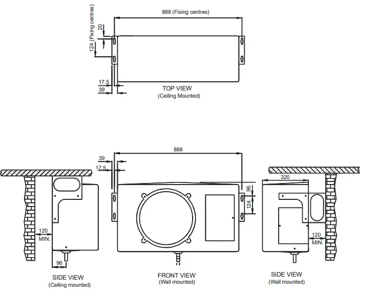
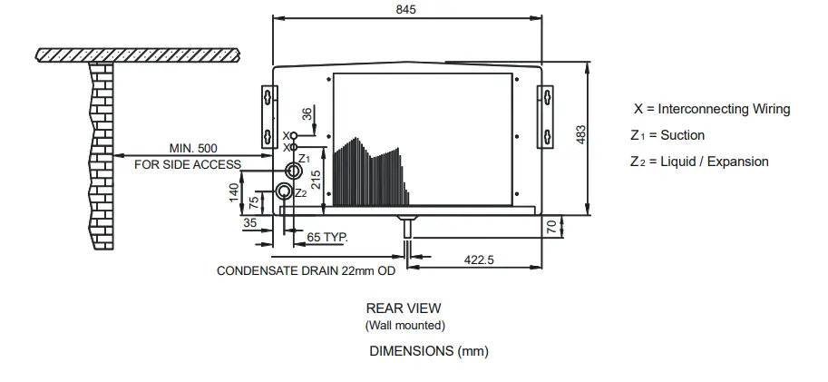
CX(E) DIMENSIONS 

INSTALLATION
| CONTENTS | |||
| PARTS DESCRIPTION | QTY | ACTION | |
| Envelope containing operating instructions and Declaration of Conformity | 1 | Pass to the end user. | |
| Mounting brackets | 2 | Use to hang unit. | |
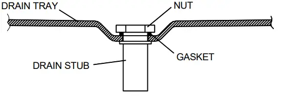
| Drain Stub/Nut/Gasket | 1 | Fitted by installer. | |
| Drain stub adaptor | 1 | Convert to ¾” drain if required. | |
| Screw M5 | 6 | To fix brackets to unit. | |
| Washer nylon | 6 | To fix brackets to unit. | |
| Washer M5 shakeproof | 6 | To fix brackets to unit. | |
| Reducing flare nut 1/2” – 3/8” | 1 | Fit to liquid connection on the CXE 70 indoor unit when matched with a CKC 60 outdoor unit | |
The unit may be mounted on a wall or solid ceiling using brackets supplied. It should be matched with the appropriately sized outdoor unit; this instruction should be used in conjunction with the outdoor unit installation instructions.
UNIT COMBINATIONS
- Fit all kits prior to installing the unit. (Heater kit is easier to fit when unit has been mounted).
- Ensure that the mounting surface will support the operating weight of the unit (see table below).
- Mark out the mounting positions and drill holes to suit 6mm rawlbolt shields or equivalent strength fasteners (ensure that the unit is positioned to give sufficient access (min 0.5m) to the removable side panel).
- Fix the mounting brackets to the unit in the correct position for wall or ceiling mounting.
- Raise the unit into position and secure the fixings, ensuring that it is square and level.
- Remove the drain tray then fit the drain stub, nut & gasket. Refit the drain tray.

NITROGEN CHARGE
The unit contains a small charge of dry nitrogen, which should be discharged into the atmosphere. This is a non-toxic, non- ozone depleting gas with no global warming potential. FITTING LOSSES, in equivalent straight lengths of pipe (m).
| FITTING | Pipe Size OD | To calculate the total equivalent length, the equivalent lengths of all fittings in a pipe run must be added to the actual length of pipe in the run: these are the fittings most likely to be used.
R = Radius of bend d = Diameter of tube C = Centres of bend | ||||
| 3/8″ | 1/2″ | 5/8″ | 3/4″ | 7/8″ | ||
| 45° Bend | 0.12 | 0.15 | 0.18 | 0.21 | 0.24 | |
| 90° Bend R/d = 1 | 0.37 | 0.43 | 0.49 | 0.55 | 0.61 | |
| 90° Bend R/d = 1.5 | 0.24 | 0.27 | 0.3 | 0.37 | 0.43 | |
| 180° Bend R/d = 1.5 | 0.73 | 0.91 | 1.1 | 1.28 | 1.46 | |
| 180° Bend C/d = 2.5 | 0.46 | 0.55 | 0.64 | 0.76 | 0.85 | |
| 90° Elbow | 0.67 | 0.85 | 1.04 | 1.25 | 1.46 | |
A. USING SUCTION AND LIQUID LINES:
With the expansion device connected to the indoor unit, the equivalent pipe run should be 45m (20m for CKC20) maximum, including a maximum lift of 7.5m. Fully insulate the suction line. Ensure the suction pipe is insulated well over the drain tray at the indoor unit. Liquid lines should be routed to avoid hot areas. This prevents flash gas forming, which may result in erratic control of liquid refrigerant to the evaporator.
| MAXIMUM EQUIVALENT LENGTH OF SUCTION LINE PIPE SIZES (m) | LIQUID LINE (m) | ||||||||
| SYSTEM | 3/8″ | 1/2″ | 5/8″ | 3/4″ | 7/8″ | 1/4″ | 3/8″ | 1/2″ | 5/8″ |
| CX(E)30 + CKC20 | 7.5 | 20 | – | – | – | 20 | – | – | – |
| CX(E)40 + CKC30 | – | 15 | 45 | – | – | – | 45 | – | – |
| CX(E)50 + CKC50 | – | 7.5 | 18 | 45 | – | – | 20 | 45 | – |
| CX(E)70 + CKC80 | – | – | 11 | 30 | 45 | – | 20 | 45 | – |
| CX(E)90 + CKC90 | – | – | 10 | 25 | 45 | – | – | 20 | 45 |
| MAXIMUM EQUIVALENT LENGTH OF SUCTION LINE PIPE SIZES (m) | LIQUID LINE | |||||||
| SYSTEM | 3/8″ | 1/2″ | 5/8″ | 3/4″ | 7/8″ | 1/4″ | 3/8″ | 1/2″ |
| CX(E)40 + CKC20 | 7.5 | 20 | – | – | – | 20 | – | – |
| CX(E)50 + CKC40 | – | 15 | 36 | 45 | – | – | 20 | 45 |
| CX(E)70 + CKC60 | – | 7.5 | 14 | 36 | 45 | – | 20 | 45 |
| CX(E)90 + CKC80 | – | – | 11 | 30 | 45 | – | 20 | 45 |
PIPE CONNECTIONS
Units are supplied with the following male flare connections (sizes in inches):
| INDOOR UNIT | CX(E)30 | CX(E)40 | CX(E)50 | CX(E)70 | CX(E)90 |
| LIQUID / EXPANSION | 3/8″ | 3/8″ | 3/8″ | 1/2″ | 1/2″ |
| SUCTION | 1/2″ | 1/2″ | 1/2″ | 5/8″ | 5/8″ |
| OUTDOOR UNIT | CKC20 | CKC30 | CKC40 | CKC50 | CKC60** | CKC80 | CKC 90 |
| LIQUID / EXPANSION | 3/8″ | 3/8″ | 3/8” | 3/8″ | 3/8” | 1/2″ | 1/2″ |
| SUCTION | 1/2″ | 1/2″ | 1/2” | 1/2″ | 5/8” | 5/8″ | 5/8″ |
RESTRICTORS
Indoor units are supplied with restrictors fitted.
NOTE
When the CXE 40 is matched with a CKC 20.
The restrictor in the indoor unit must be changed to 0.033″ When the CXE 50 is matched with a CKC 40.
The restrictor in the indoor unit remains as a 0.050″ When the CXE 70 is matched with a CKC 60.
The restrictor in the indoor unit must be changed to 0.057″ When the CXE 90 is matched with a CKC 80.
The restrictor in the indoor unit must be changed to 0.063″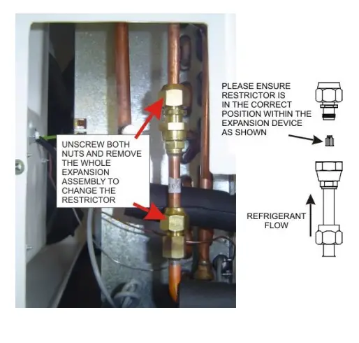
INTERCONNECTING PIPEWORK
- The indoor unit has a low pressure charge of N2, which may be safely released into the atmosphere before connection. The service valves on the outdoor unit should remain closed (IN, fully clockwise) until pipework has been fitted and system evacuated.
- Connecting the pipework
- Remove the flare nuts from the suction and liquid service valves.
- Ensure that the suction line is fully insulated: if an expansion line is used this should also be fully insulated.
- Place the flare nuts over the incoming pipework and flare the pipe ends. The use of a little refrigeration oil on the flaring tool will help.
- Connect the pipework between the units. Do not leave pipe ends, valves etc. open to the atmosphere.
- R407C is very hygroscopic and will absorb damaging levels of moisture if left open.
Always use two spanners when tightening the flare nuts to avoid twisting the pipes. Use a small amount of refrigerant oil on the mating surfaces. - Sight glasses and filter driers are not necessary, but if required should be fitted between the outdoor unit liquid shut off valve and the expansion device.
CKC REFRIGERANT
EVACUATING
- Connect a vacuum pump to the service ports on the outdoor unit valves and evacuate the system to 1000 microns (1 Torr) or better and allow to be held for a minimum of 15 minutes.
- Replace the caps on the service ports, (torque to 25NM).
ADDING REFRIGERANT
- All units are fitted with head pressure control. The link wire across the orange terminals allows the fan to operate at full speed. THIS SHOULD BE REMOVED AFTER CHARGING
- If a manual HP cut-out is fitted, ensure that the reset button is depressed.
- A 3 minute delay occurs between successive compressor operations.
- R407C should be introduced through the Schrader valve on the indoor unit, or the service port on the suction service valve on the outdoor unit. No other refrigerant must be used.
No extra POE oil needed with liquid lines. Charges shown are for guidance: actual charge will depend on the individual application. It is recommended that you charge to a sweat line on the outlet of the evaporator and/or a full sight glass if fitted.Charge based on:-
Liquid line Expansion line 1/4″ 3/8″ 3/8″ 1/2″ 5/8″ 25 g/m 60 g/m 16 g/m 30 g/m 48 g/m Additional POE oil 25g per 350g of additional refrigerant to a maximum of 300g NOTE: The new 50 Series CKC are supplied with a Nitrogen holding charge. See pages 12 & 13 for refrigerant charge information.
- Run the system for a few minutes to allow it to stabilize. Where possible, charge to a sweat line on the evaporator. Typical suction pressure on short lines at UK conditions should be approx. 3.8bar (55 psig).
- Head pressure controller
The head pressure controller is factory set to suit the refrigerant. It may be necessary to adjust this to suit site conditions, to raise or lower the nominal head pressure.
- With the system switched off, connect a high pressure gauge to the liquid line service valve.
- Switch on the system, and run for a few minutes to stabilise.
- The head pressure should be approximately:
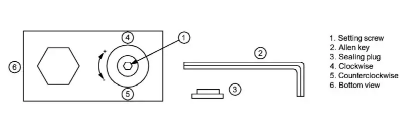
R407C: 275-280 psig (18.9-19.6barg) to achieve this remove sealing plug and insert 2mm or 5/64” allen key into setting screw. Turn allen key clockwise (+) or counter clockwise (-) to readjust the setting. Do not turn setting screw more than 3 turns clockwise (+3).
Use following table as a quick guideline for setting:
After adjustment, re-insert sealing plug and make sure that it is properly fitted. IP65 protection requires firmly sealed plug
NOTES: Tolerances for condensing temperatures setpoint: ±2K Min fan speed (0 rpm) and fan cut in pressure 200 psig (13.8 barg) are factory set and not adjustable.
NOTE: The condenser fan may stop if the operating pressure drops below 200 psig (13.8 barg)
CXE PUMP DOWN 17 SERIES MATCHED WITH CKC 50 SERIES UNITS WITH MICROCHANNEL COIL
| System | Part Number | Liquid Line | ||||||||||
| CXE | CKC | 5 | 10 | 15 | 20 | 25 | 30 | 35 | 40 | 45 | ||
|
R407C | CX(E)30 + CKC20 | 55917006 | 55050800 | 829 | 954 | 1079 | 1204 | |||||
| CX(E)40 + CKC30 | 55917007 | 55050801 | 1034 | 1334 | 1634 | 1934 | 2234 | 2534 | 2834 | 3134 | 3434 | |
| CX(E)50 + CKC50 | 55917008 | 55050803 | 1366 | 1666 | 1966 | 2266 | 3816 | 4366 | 4916 | 5466 | 6016 | |
| CX(E)70 + CKC80 | 55917009 | 55050805 | 1490 | 1790 | 2090 | 2390 | 3940 | 4490 | 5040 | 5590 | 6140 | |
| CX(E)90 + CKC90 | 55917010 | 55050806 | 2400 | 2950 | 3500 | 4050 | 6100 | 6960 | 7820 | 8680 | 9540 | |
LOW TEMPERATURE CXE PUMP DOWN 17 SERIES MATCHED WITH CKC 50 SERIES UNITS WITH MICROCHANNEL COIL
| System | Part Number | Liquid Line | ||||||||||
| CXE | CKC | 5 | 10 | 15 | 20 | 25 | 30 | 35 | 40 | 45 | ||
|
R407C | CXE 40 + CKC 20 | 55917007 | 55050800 | 739 | 864 | 989 | 1114 | |||||
| CXE 50 + CKC 40 | 55917008 | 55050802 | 956 | 1256 | 1556 | 1856 | 3406 | 3956 | 4506 | 5056 | 5606 | |
| CXE 70 + CKC 60 | 55917009 | 55050804 | 1350 | 1650 | 1950 | 2250 | 3800 | 4350 | 4900 | 5450 | 6000 | |
| CXE 90 + CKC 80 | 55917010 | 55050805 | 1590 | 1890 | 2190 | 2490 | 4040 | 4590 | 5140 | 5690 | 6240 | |
ELECTRICAL CONNECTIONS
- Cables are routed to the terminal block via the cable cord grips at the rear of the unit and then through the back of the electrics box (see page 2).
- Cables MUST be size compatible with the recommended system fuse.
FUSES
| SYSTEM | COOL ONLY | WITH ELECTRIC HEATER |
| 1PH | 1PH | |
| CXE 30 | 5A | 16A |
| CXE 40 | 5A | 16A |
| CXE 50 | 5A | 16A |
| CXE 70 | 5A | 16A |
| CXE 90 | 5A | 16A |
| SYSTEM | 1PH | 3PH |
| CKC 20 | 16A | – |
| CKC 30 | 16A | – |
| CKC 40 | 20A | – |
| CKC 50 | 16A | – |
| CKC 60 | 20A | – |
| CKC 80 | 25A | 10A/PH |
| CKC 90 | 25A | 16A/PH |
WIRING DIAGRAM
CXE PUMP DOWN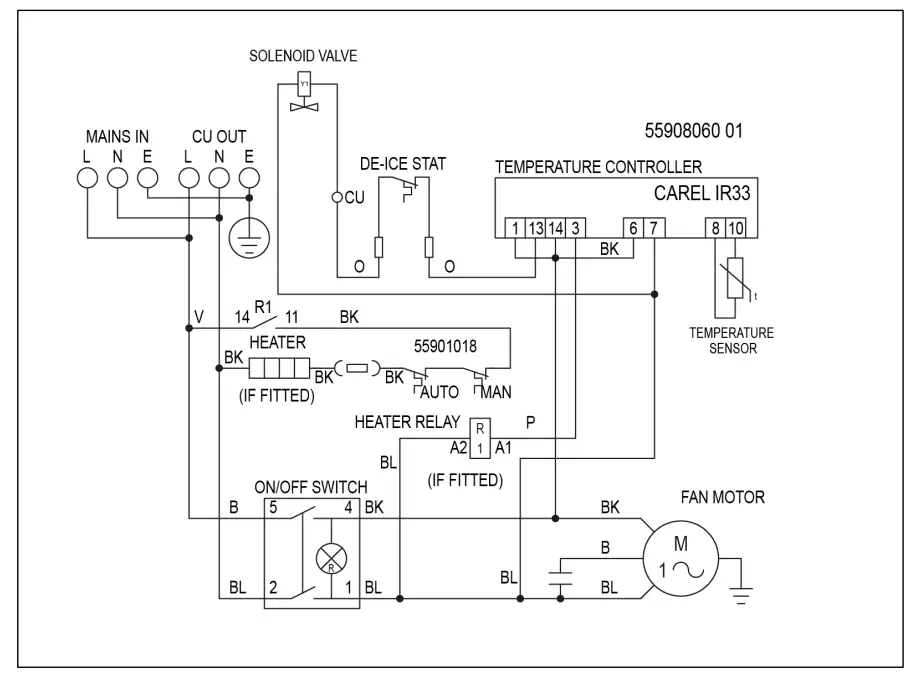
Note: Only ‘Mains in’ supply needs connecting when running system on pump down, no need to connect to ‘CU OUT’ Terminals
CKC PUMP DOWN 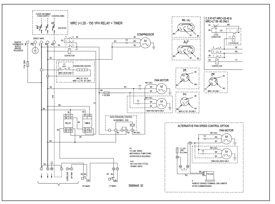
Note: Only ‘Mains in Live, Neutral & Earth’ supply needs connecting when running system on pump down, no need to connect to ‘Remote thermostat -8’ or ‘Control wire – 42’ or ‘To Evaporator unit’ Terminals
TIMER RELAY SETTINGS 
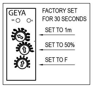
Note: Set for minimum compressor off time, minimum 30 seconds
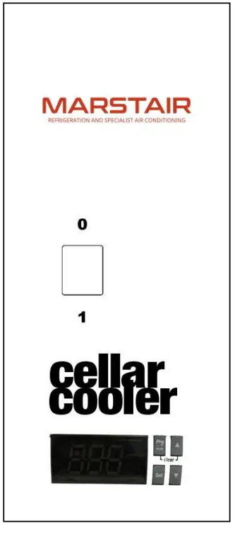
CXE ELECTRONIC COOLING SYSTEM CONTROLS
CAREL IR33 Controller
ON/OFF SWITCH
The switch operates the fan motor and is illuminated when power is supplied to the indoor unit. When switched OFF, the fan stops, the switch remains illuminated and the crankcase heater in the outdoor unit (if fitted) remains live.
| Minimum Set Temperature 8°C | |
| INDOOR UNIT | OUTDOOR UNIT |
| CX(E) 30 | CKC 20 |
| CX(E) 40 | CKC 30 |
| CX(E) 50 | CKC 50 |
| CX(E) 70 | CKC 80 |
| CX(E) 90 | CKC 90 |
| Minimum Set Temperature 4°C | |
| INDOOR UNIT | OUTDOOR UNIT |
| CXE 40 | CKC 20 |
| CXE 50 | CKC 40 |
| CXE 70 | CKC 60 |
| CXE 90 | CKC 80 |
TEMPERATURE CONTROL (Do not set the controller below 4⁰C.)
The SET temperature is factory set at 12⁰C.
The digital display normally displays the return air temperature.
To change the SET temperature, press and hold down the SET button. If no alarms active, the ‘St1’ label appears and the current value is shown on the screen and will flash.
To change the Setpoint value, press ▲ and ▼ keys within 60 seconds.
The display will revert to the return air temperature after 60 seconds.
The fitted de-ice thermostat will activate a de-ice cycle when there is a build up of ice on the evaporator coil.
Cellarators will only heat a room if the electric heater option is fitted.
Displaying inputs on screen display
Press ▼ to display the current input. There are 6 inputs to select from to display onto the screen. These are as follows:
- b1: probe 1;
- b2: probe 2;
- di1: digital input 1;
- di2; digital input 2;
- St1: set point 1;
- St2: set point 2;
Press ▲ and ▼ to select the input to be displayed. Press set for 3 seconds to confirm your choice.
To display the live temperature in the room you need to select b1: probe 1
WARNING: The following actions could damage your system:
- Switching the unit OFF and ON quickly
- Setting the unit to HEAT and then back to COOL quickly
NB: Allow at least 3 minutes between the above actions.
CKC INSTALLATION
MOUNTING
Whether floor or wall mounted, it is essential that the mounting surface is capable of supporting the unit weight. Leave space around the unit for air circulation and access for installation and maintenance.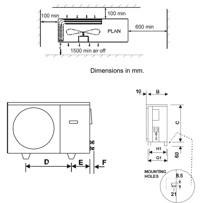
- Pipe sizes are based on:-
Minimum of 3.8 m/s (750 fpm) suction gas velocity for horizontal or downflow.
Minimum of 7.6 m/s (1500 fpm) suction gas velocity for upflow.
Maximum of 15.2 m/s (3000 fpm) suction gas. - Where vertical risers exceed 3m, oil traps must be formed in the pipe. This will help ensure that oil returns to the compressor. Typically fit an oil trap every 3m with a trap at the bottom of the riser.Individual pipe runs to a maximum of 45m (20m for CKC20), including 7.5m lift, are permissible with liquid lines. Performance is based on 7.5m pipe runs. Correctly sized pipes for each installation will result in no significant loss of capacity on extended pipe runs.
CKC PIPEWORK
- Pipe sizes are based on:-
- In calculating equivalent lengths of pipe runs, the effect of bends and fittings must be taken into account. The table below covers the fittings most likely to be encountered in this installation. The equivalent lengths of all the fittings in a pipe run should be added together and the total added to the actual pipe length in order to calculate the total equivalent length.
- Use the shortest possible route, avoiding sharp bends.
- Completely insulate the suction line, fully over the indoor unit drain tray.
CX INDOOR UNIT COMPONENT IDENTIFICATION 
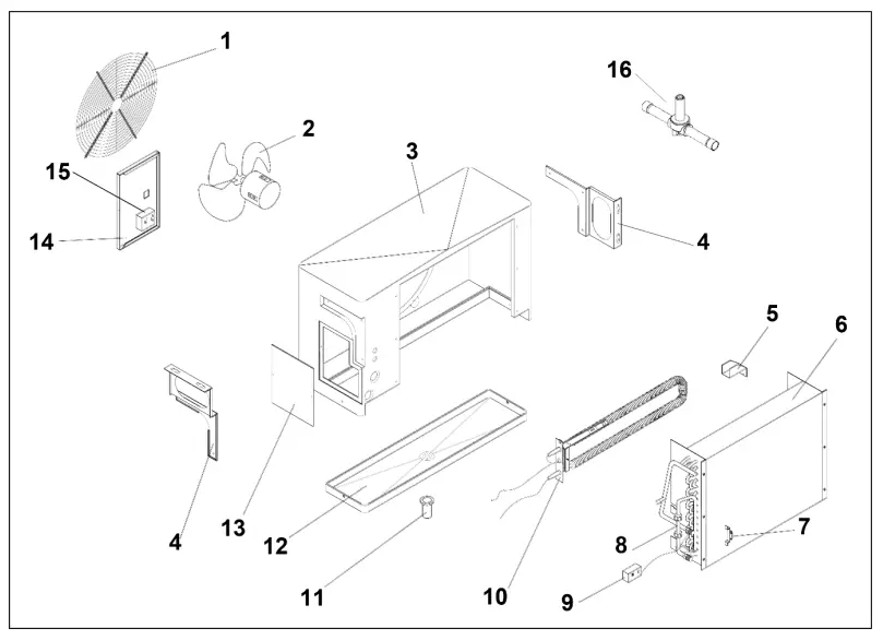
| 1 | Grille | 9 | De-ice stat |
| 2 | Fan / motor | 10 | Heater assembly (option) |
| 3 | Case | 11 | Drain stub adaptor |
| 4 | Wall / ceiling mounting brackets | 12 | Drain tray |
| 5 | Heater bracket | 13 | Side access panel |
| 6 | Coil assembly | 14 | Electrics box door |
| 7 | Thermostat bulb & bracket | 15 | Thermostat |
| 8 | Restrictor assembly | 16 | Solenoid Valve |
INSIDE VIEW OF ELECTRICS BOX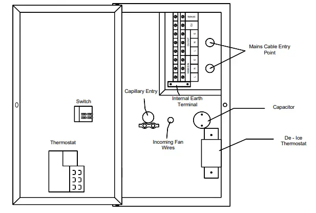
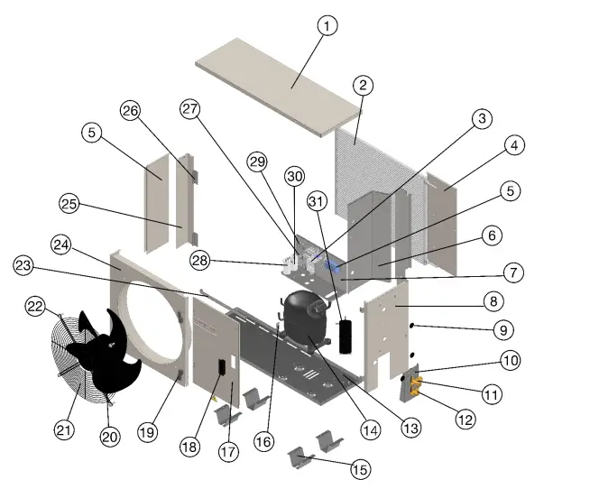
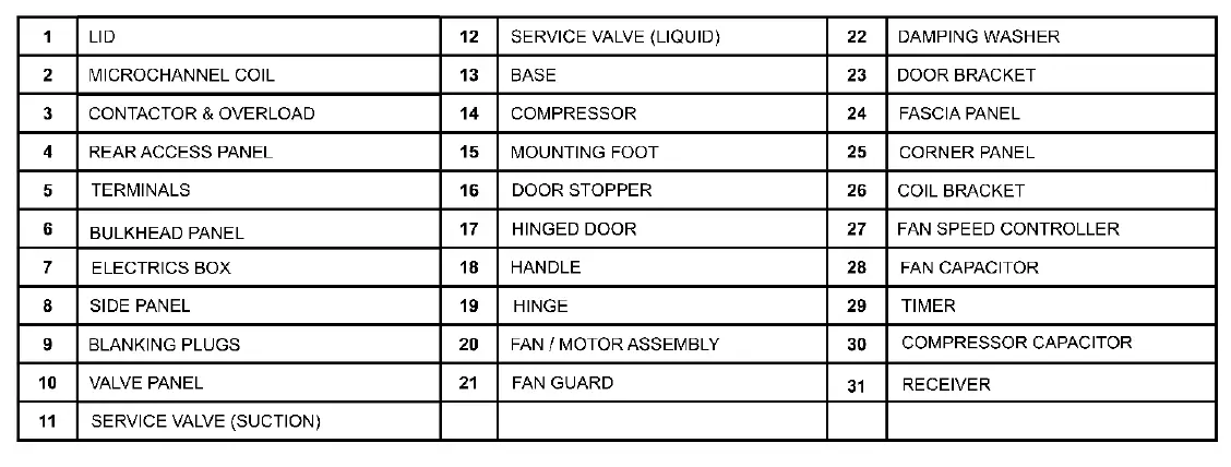
CKC OUTDOOR UNIT COMPONENT IDENTIFICATION

Commissioning Check List
The following information will be required to validate your 5yr parts warranty
| Check and record | Value | Time Held For |
| Leak (tightness) test pressure | (bar) | (min) |
| Strength (pressure) test pressure | (bar) | (min) |
| Evacuation level | (microns) | (min) |
| Value | |
| Low pressure (gauge) | (barg) |
| Suction line temperature | (°C) |
| Evaporator superheat | (K) |
| Evaporator air ON / OFF | (°C) (°C) |
| High pressure (gauge) | (barg) |
| Liquid line temperature | (°C) |
| Condenser sub cooling | (K) |
| Condenser air ON / OFF | (°C) (°C) |
| Compressor current | (A) |
| Head pressure control set | (Y/N) |
| Refrigerant type | |
| Charged weight | (Kg) |
| Additional POE oil added | (g) |
| Pipe run length | (m) |
| Suction pipe size | (ʺ) |
| Liquid / Expansion pipe size | (ʺ) |
TEV LTD, ARMYTAGE ROAD, BRIGHOUSE, WEST YORKSHIRE, HD6 1QF.
TEL: + 44 (0) 1484 405600
FAX: +44 (0) 1484 405620
EMAIL: [email protected]
WEB: www.marstair.com


