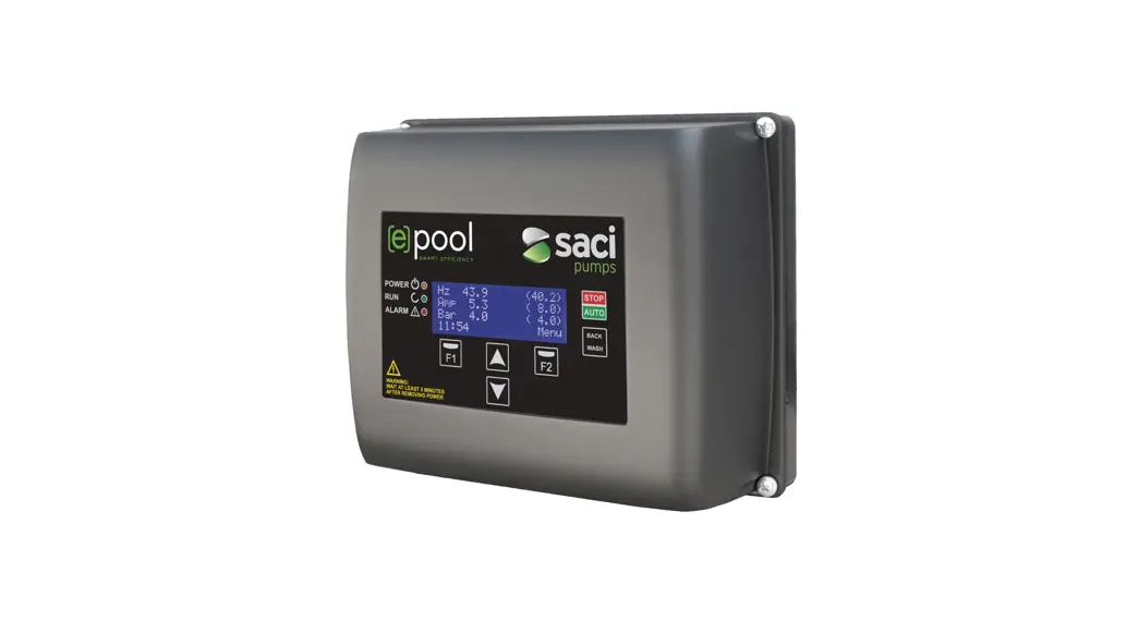
![]() ejoy New Speed Control System
ejoy New Speed Control System
Instruction Manual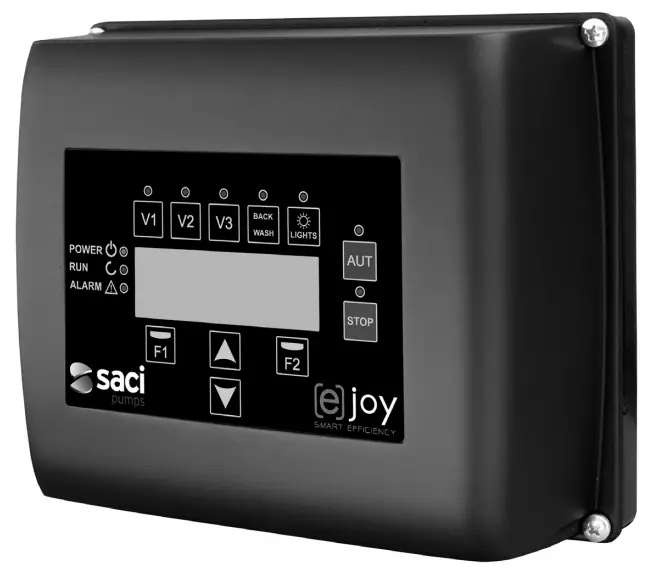
SAFETY RULES
Before installing and using the product:
- Carefully read the whole of this manual.
- Check that the data indicated on the plate is desired information and is appropriate for the installation, and in particular that the nominal voltage of the pump is compatible with that of the installation.
- The installation and maintenance must be carried out solely and exclusively by authorised personnel, responsible for making the electrical connections in accordance with the current safety regulations.
- The pump must not be used by people with reduced physical, sensory or mental capabilities, or without the ue experience or knowledge, except if a person responsible for their safety has explained the instructions and supervised their operation of the pump.
- Do not let children play with the pump.
- The manufacturer accepts no liability for damage caused by improper use of the product and shall not be held responsible for damage caused by maintenance or repairs carried out by unqualified staff and/or using nonoriginal replacement parts.
- The use of unauthorised replacement parts, alterations of the product or improper use shall automatically render the product guarantee null and void.
During normal operation:
- Before removing the cover of the speed variator, connect the mains voltage and wait 5 minutes for the electronic circuit board to discharge any residual voltage inside.
- Never disconnect the variator while the motor is rotating. This action can cause irreparable damage to the speed variator and affect the other electronic systems connected to the same electric grid.
- Although the pump is not operational, the electrical supply must still be cut off to the whole speed variator for any maintenance work.
- If there are any anomalies in the installation, the pump can be stopped manually using the button STOP for this purpose.
TECHNICAL DATA
Nominal values:
| Power supply voltage (V) | 220-240 V (1~ – 50/60Hz) |
| Operating speed (RPM) | 700 r.p.m – 2800 r.p.m |
| Maximum current (A) | 11:00 AM |
| Protection rating | IP 55 |
Limits of use:
- Minimum ambient temperature: -10ºC
- Maximum ambient temperature: +40ºC
- Variation in the supply voltage: +/- 10%
INSTALLATION / ASSEMBLY
Before installing the pump, carefully read the whole of this manual and consult the safety rules valid in each country.
Installation of the pump:
- It must be installed in a well ventilated area, protected from damp and direct exposure to the sun and rain. Failure to comply with these indications can significantly reduce the life of the speed variator.
- Before making the electrical connections, ensure the cable used to provide power to the pump is not live.
- Carefully verify the electrical data indicated in the specifications plate of the speed variator before connecting the electric current.
- The electric power cables to the pump must be of the correct size for the nominal consumption of the motor and the length of cable required.
- Also ensure that the grid has electrical protection; a high-sensitivity differential switch (30 mA, class B for industrial applications) is particularly recommended.
- In addition to the differential switch, it is advisable to install magnetothermal protection to control the power supply to the pump.
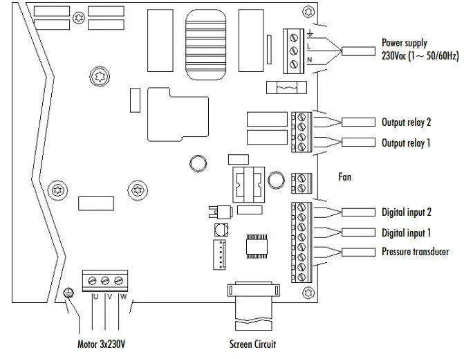
ELECTRICAL CONNECTIONS
| Signal | Description |
| Outputs relay 1 and 2 | Outputs that acts depending on how they have been programmed. These outputs are potential free and have a maximum load of 5 amperes at 230 Vac. |
| Fan | When wall-mounted, as there is no cooling from the motor’s own fan, the ventilation system of the wall mounting shall be used for this cooling. This output is at 24Vdc and is activated whenever thepump is running. |
| Digital inputs 1 and 2 | Any potential free contact that will perform the programmed functions can be connected to these inputs. N.B. Do not apply voltage to these inputs. |
| Pressure transducer | If it is connected, it will be used by the speed variator to determine the pressure of the installation as well as the pressure during the “BACK WASH” cycle. |
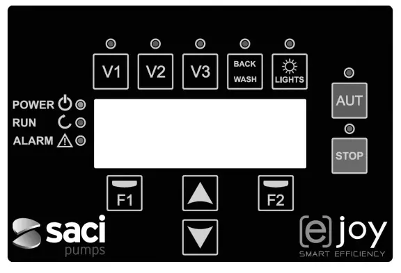
| Key | Function |
| V1 | Timed pump activation at speed 1 |
| V2 | Timed pump activation at speed 2 |
| V3 | Timed pump activation at speed 3 |
| AUT | To activate the normal operation of the pump |
| STOP | To disable the pump at any time |
| BACK WASH | To initiate the filter cleaning cycle (back wash) |
| LIGHTS | Manually activate lighting time |
| F1 | Key to activate the text on the screen |
| F2 | Key to activate the text on the screen |
| Keys for moving around the menu | |
| POWER | Indicates voltage |
| RUN | Indicates that the pump is operating |
| ALARM | Indicates that there is an active alarm |
MAIN SCREEN
This screen will show the current status of the pump: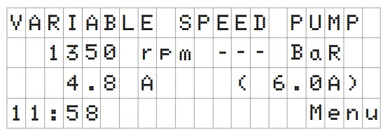 You can directly view the instantaneous rotational speed of the motor, the pressure of the installation (only if the pressure transducer is installed) and the instantaneous consumption of motor. In brackets, just to the side of the instantaneous consumption, you can see the nominal consumption of the motor entered in the start-up wizard (point 8 of this manual).
From this screen, if you click on the keys ( ![]() ) or (
) or ( ![]() ), you can directly access the display menu. This acts a short cut for checking data you need view without having to access the settings menu.
), you can directly access the display menu. This acts a short cut for checking data you need view without having to access the settings menu.
OPERATION MODE
The purpose of all pumps designed for swimming pool cleaning is to keep the water clean and in optimum ondition. The most notable development is that with the logic of the speed variator, this process is achieved with high energy savings.
The variator enables the operation of a pump in the installation, in addition to being able to control the automatic activation of the pool lights and also help to clean the filter, in addition to other functions.
There is a daily setting of various filtration sequences (up to 4 sequences every day), in which the pump’s operating speed can also be indicated.
The default of pump operation mode is automatic. Once time bands and the days of the week on which filtering is required have been indicated, the pump will filter at the speed indicated for each band. It is here where we must take into account that the slower the operating speed, the greater the energy savings.
The keyboard includes 3 buttons identified as V1, V2 and V3, which enable timed operation of the pump at the speed set in the corresponding parameter, in case the pump needs to be activated manually.
If there is a pressure transducer installed, the system will monitor the pressure of the installation at all times, to warn if it detects excess soiling in the filter. Once this warning has been received, or at any other time, when the button “BACK WASH” is pressed, a simple wizard will guide you through cleaning the filter. This wizard will tell you to move the filter valves to cleaning mode, then rinse and finally back to filtration.
START-UP
The first time you apply voltage to your unit, you will see parameter 1.1 that belongs to menu 1 General Setup, which at the same time is the start-up wizard.
You will also see this screen if you restore the factory settings.
In this menu, enter the basic parameters of the installation prior to programming the time intervals that you wish to have the pump filtering. Select the desired language with the (
 ![]() ) key and, with the F2 key (Next), move on to parameter 1.2 to continue with the set-up wizard.
) key and, with the F2 key (Next), move on to parameter 1.2 to continue with the set-up wizard.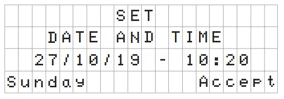 In this parameter enter the date and time. The speed variator will be overned by this for scheduling the start and stop times. Continue with F2 key to access the screen where you will enter the nominal current of the motor, indicated on its specifications plate.
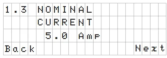 With the keys (
 ![]() ) and (
) and ( ![]() ) you can increase and decrease, respectively, the nominal consumption of the pump motor. Use the F2 key to move on to menu 1.4.
) you can increase and decrease, respectively, the nominal consumption of the pump motor. Use the F2 key to move on to menu 1.4.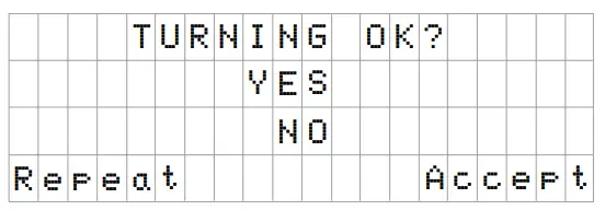 This screen shows a sequence of starting and stopping the motor at low speed, to be able to see if the motor is rotating in the correct direction. If it is not, the keys (
 ![]() ) and (
) and ( ![]() ) invert the rotation direction.
) invert the rotation direction.
This is the last screen in the startup wizard.
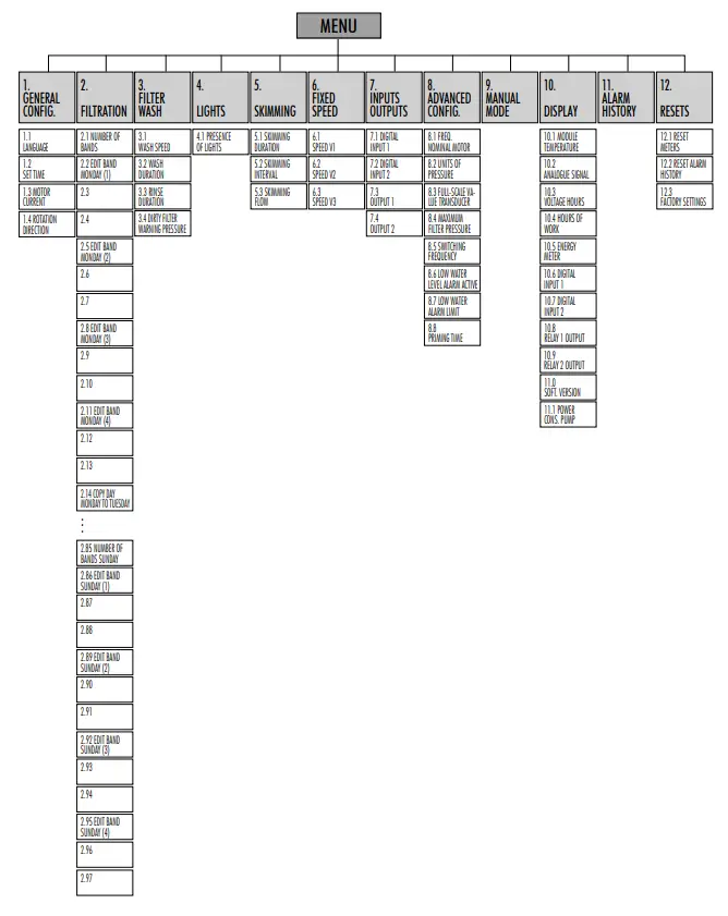
SETUP MENU
| 1. GENERAL CONFIG | ||||||
| Par. | Description | Units | VALUES | Notes | ||
| Default | Min. | Max. | ||||
| 1.1 | LANGUAGE | 1.1 | English | — | — | To define the language used to interact with the variator. |
| 1.2 | SET TIME | To adjust the date and time of the variator. | ||||
| 1.3 | MOTOR CURRENT | A | 5 | 0.1 | 11 | Indicate the consumption in amperes AT 400V found on the motor specifications plate. |
| 1.4 | ROTATION DIRECTION | 0 | 0 | 1 | Modify the motor rotation direction, if it is rotating anticlockwise. | |
| 2. FILTRATION | ||||||
| Par. | Description | Units | VALUES | Notes | ||
| Default | Min. | Max. | ||||
| 2.01 | NUMBER OF BANDS MONDAY | 0 | 0 | 4 | The number of times the swimming pool water must be recirculated per day (Monday). | |
| 2.02 | EDIT BAND MONDAY* (1) | 00:00 | Sets the start time of band 1. | |||
| 2.03 | 24:00 | Sets the end time of band 1. | ||||
| 2.04 | rpm | 1400 | 700 | 2800 | Sets the rotational speed of band 1. | |
| 2.05 | EDIT BAND MONDAY (2) | 00:00 | Sets the start time of band 2. | |||
| 2.06 | 24:00 | Sets the end time of band 2. | ||||
| 2.07 | rpm | 1400 | 700 | 2800 | Sets the rotational speed of band 2. | |
| 2.08 | EDIT BAND MONDAY (3) | 00:00 | Sets the start time of band 3. | |||
| 2.09 | 24:00 | Sets the end time of band 3. | ||||
| 2.10 | rpm | 1400 | 700 | 2800 | Sets the rotational speed of band 3. | |
| 2.11 | EDIT BAND MONDAY (4) | 00:00 | Sets the start time of band 4. | |||
| 2.12 | 24:00 | Sets the end time of band 4. | ||||
| 2.13 | rpm | 1400 | 700 | 2800 | Sets the rotational speed of band 4. | |
| 2.14 | COPY DAY MONDAY TO TUESDAY** | Enables you to copy the previous time settings to the next day (Tuesday). | ||||
| Par. | Description | Units. | VALUES | Notes | ||
| Default | Min. | Max. | ||||
| 2.86 | EDIT BAND SUNDAY (1) | 00:00 | Sets the start time of band 1. | |||
| 2.87 | 24:00 | Sets the end time of band 1. | ||||
| 2.88 | rpm | 1400 | 700 | 2800 | Sets the rotational speed of band 1. | |
| 2.89 | EDIT BAND SUNDAY (2) | 00:00 | Sets the start time of band 2. | |||
| 2.90 | 24:00 | Sets the end time of band 2. | ||||
| 2.91 | rpm | 1400 | 700 | 2800 | Sets the rotational speed of band 2. | |
| 2.92 | EDIT BAND SUNDAY (3) | 00:00 | Sets the start time of band 3. | |||
| 2.93 | 24:00 | Sets the end time of band 3. | ||||
| 2.94 | rpm | 1400 | 700 | 2800 | Sets the rotational speed of band 3. | |
| 2.95 | EDIT BAND SUNDAY (4) | 00:00 | Sets the start time of band 4. | |||
| 2.96 | 24:00 | Sets the end time of band 4. | ||||
| 2.97 | rpm | 1400 | 700 | 2800 | Sets the rotational speed of band 4. | |
- There is a complete configuration for every day of the week. This manual only explains how to configure Monday and Sunday, as a summary, but the process is the same for the other days of the week.
- When the day’s settings are complete, it allows you to copy this configuration directly to the following day, saving time when setting every day individually.
| 3. LAVADO DE FILTRO | ||||||
| Par. | Description | Units. | VALUES | Notes | ||
| Default | Min. | Max. | ||||
| 3.01 | WASH SPEED | rpm | 2800 | 700 | 2800 | Sets the speed of the pump for the filter cleaning process. |
| 3.02 | WASH DURATION | min | 5 | 1 | 60 | Pump operating time during the filter wash process. |
| 3.03 | RINSE DURATION | min | 1 | 0 | 60 | Once the filter is clean, the operating time of the pump for rinse the remaining dirty water from the filter. |
| 3.04 | DIRTY FILTER WARNING PRESSURE | bar | 1,5 | 1 | 2.5 | Pressure from which a warning will appear on the screen requiring the filter to be cleaned (for this function it is necessary to install a pressure transducer). |
| 4. LIGHTS | ||||||
| Par. | Description | Units. | VALUES | Notes | ||
| Default | Min. | Max. | ||||
| 4.01 | PRESENCE OF LIGHTS | NO | NO | YES | The daily lighting cycle of the pool is programmed if it is indicated that there are lights. | |
| 4.02 | LIGHTS ON, MONDAY* | OFF | OFF | ON | Enable/disable pool lighting on Mondays. | |
| 4.03 | LIGHTS START, MONDAY* | 00:00 | Indicate the start time of the lighting cycle. | |||
| 4.04 | LIGHTS END, MONDAY* | 00:00 | Indicate the end time of the lighting cycle. | |||
| 4.23 | RGB TEST | Enables the colour sequence to be changed if there are RGB LEDs in the pool. | ||||
- There is a complete configuration for every day of the week. This manual only explains how to configure Monday, but the process is the same for the other days of the week.
| 5. SKIMMING | ||||||
| Par. | Description | Units. | VALUES | Notes | ||
| Default | Min. | Max. | ||||
| 5.01 | SKIMMING DURATION | min | 2 | 0 | 5 | To program the duration of the surface cleaning program (SKIMMING) of the pool. If 0 minutes is indicated, SKIMMING is disabled. |
| 5.02 | SKIMMING INTERVAL | h | 3 | 1 | 24 | Indicate how often the SKIMMING program is to be started. |
| 5.03 | SKIMMING FLOW | rpm | 2800 | 700 | 2800 | Tell the pump what speed is required for the SKIMMING program. |
| 6. FIXED SPEED | ||||||
| Par. | Description | Units. | VALUES | Notes | ||
| Default | Min. | Max. | ||||
| 6.01 | SPEED V1 | rpm | 950 | 700 | 2800 | Set the speed at which the pump is to run at speed V1. |
| 6.02 | SPEED V2 | rpm | 1400 | 700 | 2800 | Set the speed at which the pump is to run at speed V2. |
| 6.03 | SPEED V3 | rpm | 2800 | 700 | 2800 | Set the speed at which the pump is to run at speed V3. |
| 7. INPUTS OUTPUTS | ||||||
| Par. | Description | Units. | VALUES | Notes | ||
| Default | Min. | Max. | ||||
| 7.01 | DIGITAL INPUT 1 | Unused | Unused External stop External stop INV Fixed speed Fixed speed INV | An input can be used to perform a remote stop (the INV option is for a contact that opens to switch on) or for the pump to operate at a certain speed when the input 1 is activated or deactivated (INV option). | ||
| 7.02 | SPEED IN 1 | rpm | 1400 | 700 | 2800 | If digital input 1 is enabled for fixed speed, indicate the speed at which it is to operate when this input is given. |
| 7.03 | DIGITAL INPUT 2 | Same as parameter 7.01 but for input 2. | ||||
| 7.04 | SPEED IN 2 | Same as parameter 7.02 but for input 2. | ||||
| 7.05 | OUTPUT 1 | OFF | OFF Salt chlorinator Wash Alarm (NO) Alarm (NA) Run Clock (NO) Clock (NA) | Relay 1 can be programed to be activated (or deactivated for NC-terminated options) whenever the pump is started, when the pump is filtering (saline chlorinator), when an alarm occurs or when a certain programming cycle is running. | ||
| 7.06 | SCHEDULE PROGRAMME 1 | OFF | OFF M-Su M-F S-Su M, T,X,T,F,S,Su | This parameter is visible only if one of the 2 clock options is selected in the previous parameter. It enables the days or the block of days to be programmed, such as M-Su that refers to Monday through Sunday, in which the relay is to be activated. | ||
| 7.07 | START TIME PROGRAMME 1 | 00:00 | Indicate start time for programme 1. | |||
| 7.08 | STOP TIME PROGRAMME 1 | 00:00 | Indicate start time for programme 2. | |||
| 7.09 | OUTPUT 2 | Same as parameter 7.05 for output 2. | ||||
| Par. | Description | Units. | VALUES | Notes | ||
| Default | Min. | Max. | ||||
| 7.10 | SCHEDULE PROGRAMME 2 | OFF | OFF M-Su M-F S-Su M, T,X,T,F,S,Su | This parameter is visible only if one of the 2 clock options is selected in the previous parameter. It enables the days or the block of days to be programmed, such as M-Su that refers to Monday through Sunday, in which the relay is to be activated. | ||
| 7.11 | START TIME PROGRAMME 2 | Same as parameter 7.07 for program 2. | ||||
| 7.12 | STOP TIME PROGRAMME 2 | Same as parameter 7.08 for program 2. | ||||
| 8. PARÁMETROS AVANZADOS | ||||||
| Par. | Description | Units. | VALUES | Notes | ||
| Default | Min. | Max. | ||||
| 8.01 | NOMINAL FREQUENCY MOTOR | Hz | 2800 | 1400 | 3400 | Modifies the maximum speed of pump operation. |
| 8.02 | UNITS OF PRESSURE | Bar | Bar | PSI | You can modify the units to represent the pressure of the installation. | |
| 8.03 | FULL-SCALE VALUE TRANSDUCER | Bar | 10 | 5 | 58 | Enables you to adjust the range of detection of the transducer if its scale is not the standard 4-20 mA (0-10 Bar). |
| 8.04 | MAXIMUM FILTER PRESSURE | Bar | 2.5 | 2 | 5 | In this point, indicate the maximum pressure that the filter supports, so that in normal operation the inverter takes it into account and acts accordingly so that this pressure is never exceeded. |
| 8.05 | SWITCHING FREQUENCY | KHz | 7.7 | 2,5 | 16 | Enables you to modify the switching frequency of the variator, reducing the noise, although uncommon, of the switching at the expense of an increase in temperature of the electronics. N.B. We do not recommend modifying the default value except when expressly indicated by the Technical Department. |
| 8.06 | LOW WATER LEVEL ALARM ACTIVE | ON | ON | OFF | Enables the constant monitoring of the pump running dry, if this occurs. | |
| 8.07 | LOW WATER ALARM LIMIT | % | 75 | 50 | 90 | Value used in the mathematical algorithm that calculates the pump running dry. |
| 8.08 | PRIMING TIME | min | 2 | 1 | 10 | During the priming time, the detection of running dry will not be operative even though the monitoring is enabled. |
9. MANUAL MODE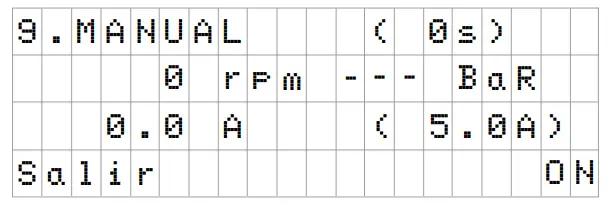 The objective of this screen is to test the pump operation, at a specific speed, for a controlled time, to correctly select the operating speeds of the cycles in section 2 of the settings menu.
Press F2 to activate the pump initially for 2 minutes at the maximum frequency of the pump. Each time you press the F2 key increases the operating time on a scale of 2 minutes, 15 minutes, 30 minutes, 1 hour, 2 hours, 4 hours or 8 hours. At any time, by pressing the F1 key, you can stop the pump operation.
Every time you press the keys ( ![]() ) or (
) or ( ![]() ) you increase or decrease, respectively, the operating speed of the pump by 10 rpm.
) you increase or decrease, respectively, the operating speed of the pump by 10 rpm.
| 10. DISPLAY | ||||||
| Par. | Description | Units. | VALUES | Notes | ||
| Default | Min. | Max. | ||||
| 10.01 | MODULE TEMPERATURE | ºC | Shows the current temperature of the power module. If the temperature is very high, the speed variator itself will limit the speed of the pump to prevent the electronics of the speed variator being damaged. | |||
| 10.02 | ANALOGUE SIGNAL | mA | 4 | 20 | Shows the value of the pressure transducer reading in mA. | |
| 10.03 | VOLTAGE HOURS | Hours | Indicates the hours the pump has been connected to the electricity grid regardless of whether it has been running or not. | |||
| 10.04 | HOURS OF WORK | Hours | Indicates the hours of pump operation. | |||
| 10.05 | ENERGY METER | kWh | Indicates the pump consumption in kWh. | |||
| 10.06 | DIGITAL INPUT 1 | 0 | 0 | 1 | Indicates whether input 1 is enabled or not; if it is enabled, the reason for this. | |
| 10.07 | DIGITAL INPUT 2 | 0 | 0 | 1 | Indicates whether input 2 is enabled or not; if it is enabled, the reason for this. | |
| 10.08 | RELAY 1 OUTPUT | 0 | 0 | 1 | Indicates whether relay 1 is enabled or not; if it is enabled, the reason for this. | |
| 10.09 | RELAY 2 OUTPUT | 0 | 0 | 1 | Indicates whether relay 2 is enabled or not; if it is enabled, the reason for this. | |
| 11.00 | SOFTWARE VERSION | Indicates the version of the software of the control panel (screen) and the power panel (aluminium radiator). | ||||
| 11.01 | POWER CONSUMED BY PUMP | W | Indicates the instantaneous power consumed by the pump. | |||
11. ALARM LOG
Shows a log of anomalies of the pump where the speed variator is connected, indicating the date, the time and the anomaly that occurred. This information is very important for detecting possible anomalies in the functioning of the installation.
| 12. RESETS | ||||||
| Par. | Description | Units. | VALUES | Notes | ||
| Default | Min. | Max. | ||||
| 12.01 | RESET METERS | NO | NO | YES | Enter YES to delete the voltage hours and the energy meter. | |
| 12.02 | RESET ALARM HISTORY | NO | NO | YES | Enter YES to reset all the faults stored in the alarm history. | |
| 12.03 | FACTORY SETTINGS | NO | NO | YES | This parameter will remove all the settings entered in the configuration of the variator, returning it to its initial status, as it was when installed for the first time. | |
11. ALARMS
| Message | Reasons | Solution(s) |
| PRESSURE WARNING: FILTER CLEANING | Indicates that the pressure entered in the parameter (DIRTY FILTER WARNING PRESSURE) has been exceeded. | Press the button BACK WASH and perform the steps indicated by the filter cleaning wizard, as the system detects a high pressure in the filter, probably due to excess soiling. |
| ALARM F01 OVERCURRENT | Indicates excessive consumption in the motor. | Check that the pump rotates freely with no obstructions. |
| The motor is communicated or has burnt out. | Disconnect the motor from the variator and check that the message disappears. If this is not the case, contact your nearest technical service. | |
| ALARM F02 SHORT CIRCUIT | Not all wires have been connected. | Check that all the cables of the motor are correctly connected to the motor itself and also to the variator. Also supervise the correct wiring of the frequency converter’s power supply. |
| Internal fault in the variator. | Contact your nearest technical service. | |
| ALARM F03 EXCESS TEMPERATURE OF THE MODULE | The power module has reached a very high temperature, compromising its reliability. | Ensure the ambient temperature does not exceed the extremes set out in this manual. Ensure the variator is properly ventilated; in this case check that the pump has a fan and that the fan cover has been installed. |
| ALARM F04 INPUT VOLTAGE | The variator is not receiving electric current, of is outside of the upper and lower limits. | The electrical supply to the variator has been interrupted. The electrical connection cable from the mains electricity to the variator has been disconnected. |
| Message | Reasons | Solution(s) |
| ALARM F06 MOTOR FAULT | The motor is communicated/disconnected. Loss of synchronism. | Check that the cables to the motor are properly connected, as the variator is not detecting the motor, or it is burnt out. There may also be a loss of synchronism of the motor during operation due to a significant, quick change in the pumping conditions. |
| ALARM F07 LOW WATER LEVEL | The variator detects that the pump is working without water in the body of the pump. | Ensure the pump aspirates the fluid correctly. |
| ALARM F08 MAXIMUM PRESSURE LIMIT | The variator detects that the filter is very soiled or at a pressure close to bursting. | Check the filter does not need cleaning and that the impulsion valves allow recirculation. |
| ALARM X13 INTERNAL ERROR | There is no communication between the control panel (cover), and the power plate (radiator). Internal fault in the variator. | Check that the flat cable that communicates both electronic circuits are well connected and tightened. There may be one-off read error of the firmware. We recommend cutting the power to the variator for a few minutes. If, when the power is reconnected to the variator, the message remains, contact your nearest technical service. |
WARRANTY
The guarantee on the speed variator is 24 months from the date of purchase: The use of non-original spare parts, alterations or improper use shall render the product warranty void.
DISPOSAL AND ENVIRONMENTAL ASPECTS
To dispose of the parts that comprise the speed variator, you must abide by the current regulations and laws of the country where the product is used. In any case, do not dispose of polluting parts into the environment.![]() This symbol on the product indicates that it should not be disposed of with other household waste.
This symbol on the product indicates that it should not be disposed of with other household waste.
This stipulation only refers to the disposal of equipment within the European Union (2012/19 /EU). It is the user’s responsibility to dispose of the equipment by delivering it to a designated collection point for the recycling and disposal of electrical equipment. For more information about equipment collection points, contact your local waste disposal agency.
DECLARATION OF CONFORMITY
declares, under its full responsibility, that the products to which this manual refers comply with the following European Directives and national action provisions:
| DIRECTIVES | NORMS |
| – Directive 2014/30/EU (EMC) | – EN 61800-3 Category C2 (EMC) |
| – Directive 2014/35/EU (Low Voltage) | – EN 61800-5-1 (LV) |
| – Directive 2012/19/EU (RAEE) | – EN 50581 (RoHS) |
| – Directive 2011/65/CE (RoHS II) | – EN 60529 (IP Code) |
Granollers, 1st February 2019
 David Ferré Ferrer
GERENTE
Camí the Can Muntanyola, 4-22 – Pol. Ind. Palou Nord
08401 Granollers (Spain)
Tel. (+34) 933 842 351
Fax (+34) 933 842 900
www.sacipumps.com
[email protected]


