
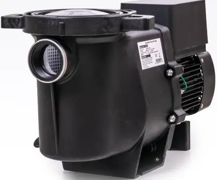
welldana 36-140010 AquaGreen 3-Speed Pump
IMPORTANT SAFETY INSTRUCTIONS
This guide provides installation and operation instructions for this pump. Consult your supplier with any questions regarding this equipment.
When installing and using this electrical equipment, basic safety precautions should always be followed:
- RISK OF ELECTRICAL SHOCK. Connect only to a branch circuit protected by a ground-fault circuit-interrupter (GFCI). Contact a qualified electrician if you cannot verify that the circuit is protected by a GFCI.
- This pump is for use with permanent installed in ground or above ground swimming pools and may also be used with hot tubs and spas if so marked. Do not use with above ground pools that can be readily disassembled for storage.
- The pump is not submersible.
- Before servicing the pump; switch off power to the pump by disconnecting the main circuit to the pump.
- Never open the inside of the drive motor enclosure.
All installations must be fitted with earth leakage or residual current protection devices, having a rated residual operating current not exceeding 30mA.
WARNING
- Do not run the pump dry. In case of dry run, mechanical seal will be damaged and the pump will start leaking. Fill the pump with water before starting.
- Before servicing the pump, switch OFF power to the pump by disconnecting the main circuit to the pump and release all pressure from pump and piping system.
- Never tighten or loosen screws while the pump is operating.
- Do not block the pump suction.
TECHNICAL SPECIFICATIONS
| Model | Advised pool volume (m³) | P1 | V/Ph/Hz | Backwash | Circulation (m³/h) | |||
| KW | Qmax (m³/h) | Xmax (m) | At 6m | At 8m | At 10m | |||
| G09L0 | 20~30 | 0.04~0.35 |
220~240/1/50 | 18.5 | 13.6 | 4.2~9.0 | ||
| G11L0 | 25~40 | 0.07~0.5 | 23.5 | 17.5 | 9.6~15.0 | 4.5~11.5 | ||
| G15L0 | 40~55 | 0.1~0.70 | 27.5 | 19.1 | 12.9~18.6 | 8.1~15.3 | 8.7~11.1 | |
| G22L0 | 60~80 | 0.14~1.0 | 32 | 21 | 13.5~23.1 | 12.0~20.1 | 10.9~16.5 | |
OVERALL DIMENSION
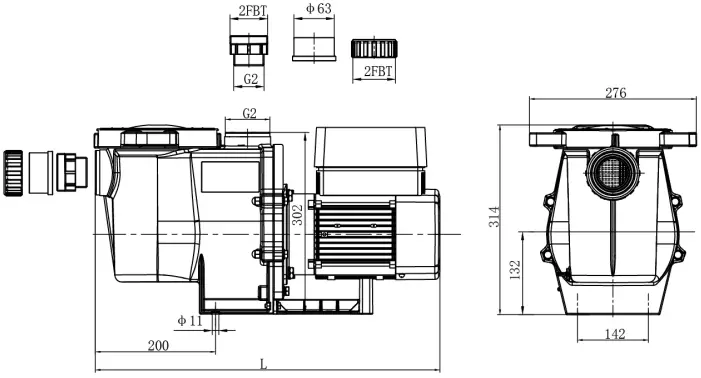
| Model | Corresponding L length (mm) |
| G09L0 | 572 |
| G11L0 | 572 |
| G15L0 | 572 |
| G22L0 | 585 |
INSTALLATION
Pump Location
- Locate pump as close to pool as practical and run suction lines as direct as possible to reduce friction loss.
- To avoid direct sunshine or heat, It is recommended to place pump indoor or in the shade.
- DO NOT install pump in a damp or non-ventilated location. Keep pump and motor at least 150mm away from obstacles, Pump motors require free circulation of air for cooling.
- The pump should be installed horizontally and fixed in the hole on the support with screws to prevent unnecessary noise and vibration.
Piping
- For improved pool plumbing, it is recommended to use a larger pipe size. When installing the inlet and outlet fittings (male adaptor), use thread sealant.
- Piping on the suction side of the pump should be the same or larger than the return line diameter, to avoid pump sucking air, which will affect efficiency of pump.
- Plumbing on the suction side of the pump should be as short as possible.
- For most installations we recommend installing a valve on both the pump suction and return lines so that the pump can be isolated during routine maintenance. However, we also recommend that a valve, elbow or tee installed in the suction line should be no closer to the front of the pump than five times the suction line diameter.
- Pump outlet piping system should be equipped with a check valve to prevent pump from the impact of medium recirculation and pump-stopping water hammer.
Valves and Fittings
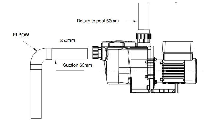
- Do not install 90° elbows directly into pump inlet. Elbows should be no closer than 250mm to the inlet. Joints must be tight. Suction line diameter must equal or be larger than the discharge line diameter.

- Flooded suction systems should have gate valves installed on suction and discharge pipes for maintenance, however, the suction gate valve should be no closer than five times the suction pipe diameter as described in this section.
- Use a check valve in the discharge line when using this pump for any application where there is significant height to the plumbing after the pump.
- Be sure to install check valves when plumbing in parallel with another pump. This helps prevent reverse rotation of the impeller and motor.
Check before initial startup
- Check whether pump shaft rotates freely;
- Check whether power supply voltage and frequency conform to the nameplate;
- Facing fan blade, direction of motor rotation is clockwise;
- It is forbidden to run pump without water.
SETTING & OPERATION
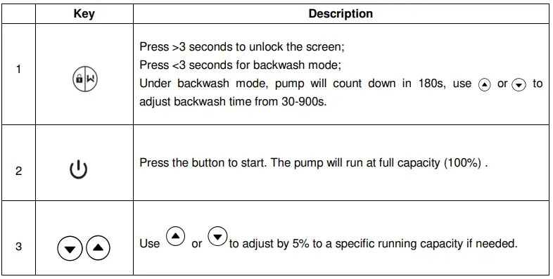
Interface
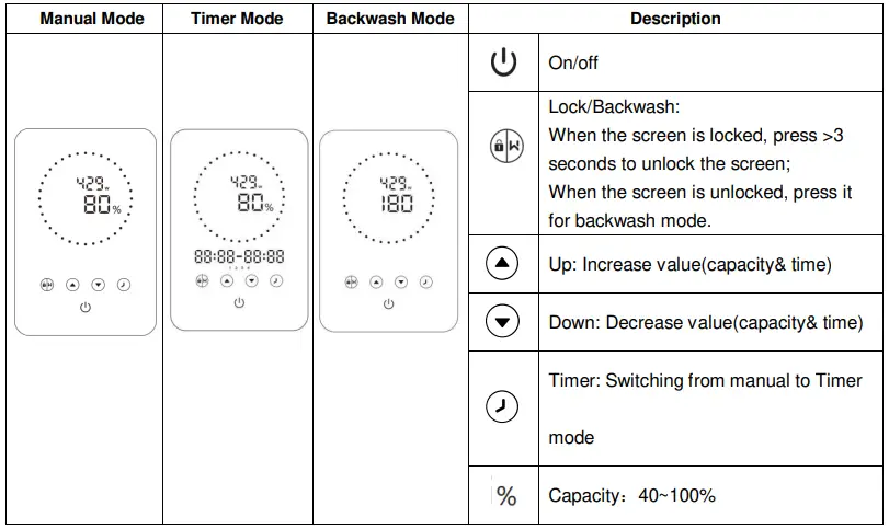
Capacity Setting
Note: The inverter module can be operated manually or automatically at regular intervals.
The system automatically saves the 4 latest valid settings.
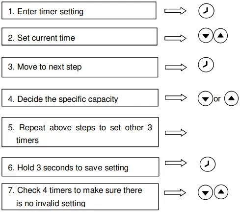
Timer Setting
- Overlap setting of time will be considered as invalid, the pump will only run based on the previous valid setting.
- During timer setting, if you want to return to the previous setting, hold
 for 3 seconds.
Parameter Setting
Under OFF mode, hold ![]() for 3 second to enter parameter settings
for 3 second to enter parameter settings
| Parameter | Description | Default Setting | Setting Range |
| 1 | Di2 | 100% | 40%~100%, by 5% increments |
| 2 | Di3 | 80% | |
| 3 | Di4 | 40% |
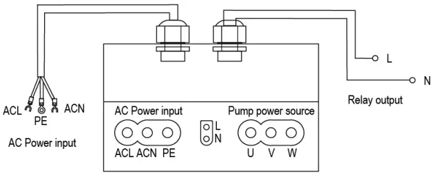
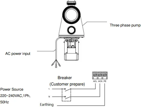
WIRING CONNECTION
Warning
All electrical wiring MUST conform with applicable National Electrical Safety Code (NESC) and National Electric Code (NEC).
Please refer to the below schematic for information on how to correctly install your pump.
EXTERNAL CONTROL(Not included in standard model)
External control can be enabled via following contacts. Pressing on/off can stop the pump even if working via an external controller.
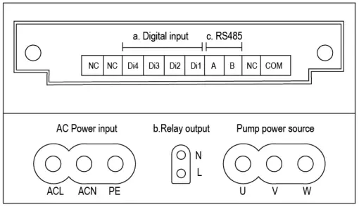
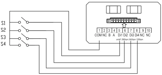
Digital Input:To enable external speed control, connect one of the digits from Di1/2/3/4 to COM. See schematic as below:
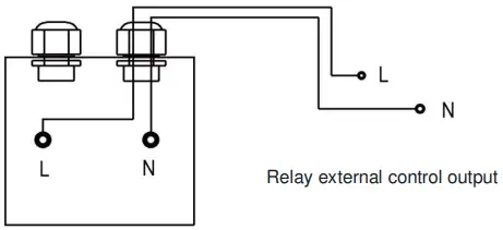
Relay Output: Connect terminal L & N to enable external control. An additional on-off Relay is necessary while bearing power is less than 500W (2.5A). See schematic as
below:
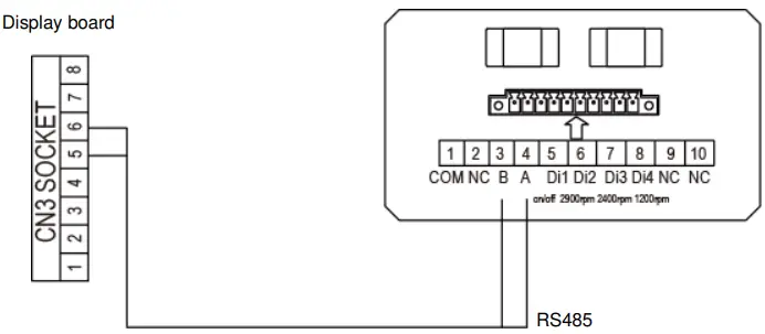
RS485: To enable external control pump running capacity, connect terminal A and B, via Modbus485 communication protocol.
Display board
TROUBLE SHOOTING
| Problem | Corrective solution |
| Pump Does Not Start | • Power Supply fault, disconnected or defective wiring • Fuses blown or thermal overload open • Check the rotation of the motor shaft for free movement and lack of obstruction. • Because of long time lying idle. Unplug the power supply and manually rotate motor rear shaft a few times with a screwdriver. |
| Pump Won’t Prime | • Empty pump/strainer housing. Make sure the pump/strainer housing is filled with water and the cover o ring is clean. •Loose connections on the suction side. •Strainer basket or skimmer basket loaded with debris. •Suction side clogged. • Distance between pump inlet and liquid level is higher than 2.5m, height of pump installation should be lowered. |
| Low Water Flow | • Pump is not primed • Air entering suction piping • Basket full of debris • Inadequate water level in pool |
| Pump being noisy | • Air leak in suction piping, cavitations caused by restricted or undersized suction line or leak at any joint, low water level in pool, and unrestricted discharge return lines. • Vibration caused by improper installation, etc. • Damaged motor bearing or impeller (need to contact the supplier for repair) |
ERROR CODE
| Item | Code | Description | Analysis |
| 1 | E001 | Abnormal input voltage | Not faulty |
| 2 | E002 | Output over current | Not faulty |
| 3 | E101 | Heat sink over heat | Contact your supplier |
| 4 | E102 | Heat sink sensor error | Contact your supplier |
| 5 | E103 | Master driver board error | Contact your supplier |
| 6 | E201 | Circuit board error | Contact your supplier |
| 7 | E202 | Master board EEPROM reading failure | Contact your supplier |
| 8 | E203 | RTC time reading error | Contact your supplier |
| 9 | E204 | Display board EEPROM reading failure | Contact your supplier |
| 10 | E205 | Communication error | Contact your supplier |
| 11 | AL01 | Auto speed reduction against high temperature | Contact your supplier |
Note:
- AL01 is not an error indication: when it appears the inverter will automatically switch to a lower capacity to self protect against high internal temperature. When the temperature drops back to 68℃ the inverter will resume at the preset speed.
- When causes for E002/E101/E103 lifts, the device will resume working automatically, however when it appears a fourth time, the device will stop working, to resume operation, unplug the device and plug in & restart again.
MAINTENANCE
Emptying the strainer basket, the basket should be inspected frequently through the transparent lid and emptied when a build-up of rubbish is evident. The directions below should be followed:
- Switch off pump.
- Unscrew the strainer basket lid anti-clockwise and remove.
- Remove the strainer basket by lifting upwards from its housing.
- Empty the trapped refuse from the basket. Hose out with water if necessary.
NOTE: Do not knock the plastic basket on a hard surface as it will cause damage. - Check the strainer basket for cracks, replace the basket in the pump if OK.
- Replace the lid and ensure that it seals on the large rubber O-ring. Firm hand tightness only is required.
NOTE: Failure to undertake regular maintenance may cause damage not covered by warranty.
WARRANTY & EXCLUSIONS
Should a defect become evident during the term of warranty, at its option, the manufacturer will repair or replace such item or part at its own cost and expense. Customer will need to follow the warranty claim procedures in order to obtain the benefit on this warranty.
Under no circumstances should the manufacturer be held liable for any consequences resulting from inappropriate, incorrect installation, or mismatching of the product to pool pumps that are not compatible.
WEEE LEGISLATION
When disposing the product, please hand it over to a designated collection point for the recycling of waste electrical and electronic equipment.
The separate collection and recycling of waste equipment at the time of disposal will help ensure that it is recycled in a manner that protects human health and the environment. Contact your local authority for information on where you can drop off your water for recycling.


