Oase 6000 AquaMax Eco Premium Pond Pump Instruction Manual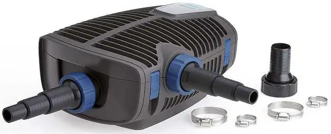
![]() WARNING
WARNING
- Disconnect all electrical units in the water from the power supply before reaching into the water. Otherwise there is a risk of injuries or death by electrocution.
- This unit can be used by children aged 8 and above and by persons with reduced physical, sensory or mental capabilities or lack of experience and knowledge if they are supervised or have been instructed on how to use the unit in a safe way and they understand the hazards involved. Do not allow children to play with the unit. Only allow children to carry out cleaning and user maintenance under supervision.
Safety information
Electrical connection
- Special regulations apply to electrical installation in outdoor areas. Only allow a qualified electrician to perform the electrical installation.
- The qualified electrician has the required professional training, knowledge and skills to perform electrical installations in outdoor areas. The qualified electrician can detect potential risks and adheres to regional and national standards, regulations and directives.
- For your own safety, please consult a qualified electrician.
- Only connect the unit if the electrical data of the unit and the power supply match.
- Only plug the unit into a correctly installed outlet. Ensure that the unit is fused for a rated fault current of max. 30 mA by means of a fault current protection device.
- Extension cables and power distributors (e.g. outlet strips) must be suitable for outdoor use (splash-proof).
- Protect open plugs and sockets from moisture
Safe operation
- Do not use the unit, if electrical lines or the housing are damaged.
- A damaged connection cable cannot be replaced. Dispose of the unit.
- The impeller unit inside the unit contains a magnet with a strong magnetic field that may affect the operation of pacemakers or implantable cardioverter defibrillators (ICDs). Keep the magnet at least 0.66 ft (0.2 m) away from any implant.
- Do not carry or pull the unit by its power cable.
- Route lines so that they are protected from damage and nobody can trip over them.
- Never make technical modifications to the unit.
- Only carry out work on the unit that is described in this manual.
- Only use original spare parts and accessories.
- Should problems occur, please contact the authorized customer service or OASE
Intended use
Only use the product described in this manual as follows:
- For pumping normal pond water for filter systems, waterfall systems and water course systems.
- For use in swimming ponds if the national regulations for installers are met.
- Only operate with the original switching power pack.
- In compliance with the technical specifications. (→ Technical data)
- Only subject to adherence to the permissible water quality values. (→ Permissible water values)
The following restrictions apply to the unit: - Never use the unit with fluids other than water.
- Never run the unit without water.
- Do not use in conjunction with chemicals, foodstuff, easily flammable or explosive substances.
- Do not connect to the domestic water supply.
- Do not use for commercial or industrial purposes.
- According to EMC (Electromagnetic Compatibility), this is a class A unit. The unit may cause malfunctions in living environments. It is the user’s responsibility to take suitable countermeasures.
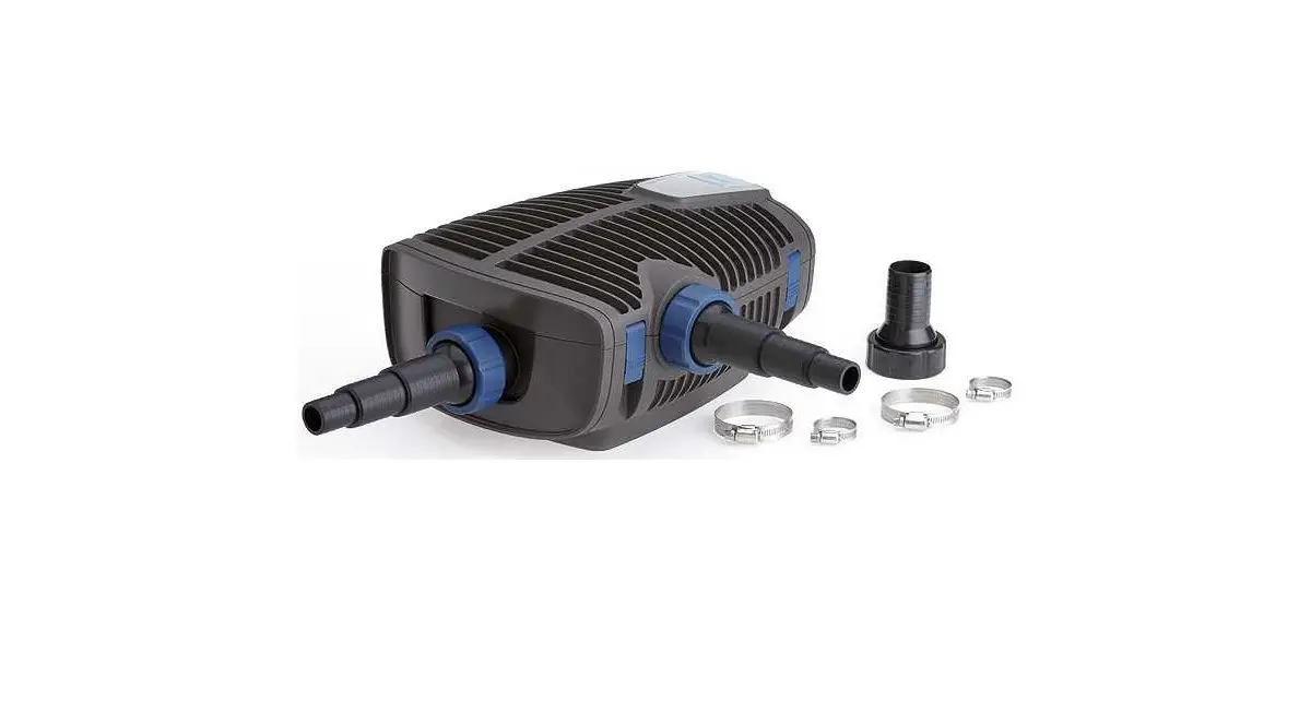
Product description
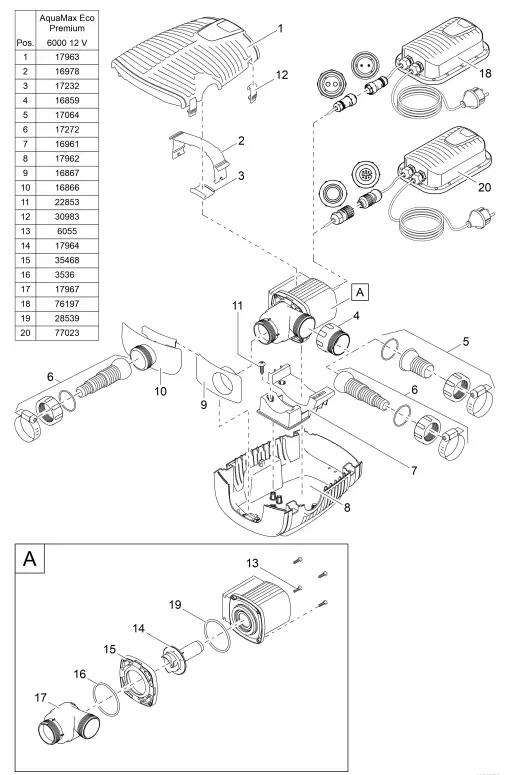
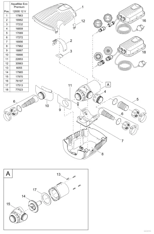
Overview
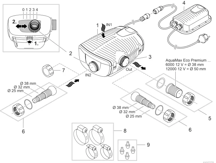
- Inlet 1 (suction side)
- Filter casing for pond bottom filtration
- Inlet 2 (suction side)
- Connection of a satellite filter or skimmer.
- The flow rate on inlet 2 and with it the intake ratio of inlet 1 and 2 is adjustable. To do so, undo the locking mechanism and push the connection to one of the following positions:
- Position 0: Inlet 2 is closed, intake only via inlet 1.
- Position 1/2/3: Inlet 2 is opened by approx. 25/50/75 %; this means intake via inlet 1 and 2 based on the set intake ratio.
- Position 4: Inlet 1 is closed, intake only via inlet 2.
- Outlet (pressure side)
- Connection of the return flow to the pond (e.g. via a water course).
- Switching power pack with power plug
- Pump power supply
- House sleeve for outlet (recommendation).
- Stepped hose adapter for inlet 2 and outlet (alternative).
- Cover cap for closing inlet 2 when it is not in use.
- Hose clips for fastening hoses on the hose sleeves.
- Rubber feet for pump holder for dry installation.
Symbols on the unit
![]() The unit is dust-proof and water-tight down to 6.56 ft (4 m).
The unit is dust-proof and water-tight down to 6.56 ft (4 m).![]() Possible hazard for persons wearing pace makers.
Possible hazard for persons wearing pace makers.![]() Only operate the unit with a safety transformer.
Only operate the unit with a safety transformer.![]() Protect the unit from direct sunlight.
Protect the unit from direct sunlight.![]() Never dispose of the unit with normal household waste.
Never dispose of the unit with normal household waste.![]() Read the operating instructions.
Read the operating instructions.
Installation variants
- Variant (a): Pond bottom filtration only
- With pond bottom filtration only, the water is drawn in only through the filter casing (inlet 1).
- Set inlet 2 to position “0”.
- Close inlet 2 with the cover cap.
- Variant (b): Pond bottom filtration and filtration via satellite filter or skimmer
- For pond bottom filtration, the water is drawn in via the filter casing (inlet 1). Inlet 2 draws in water via a satellite filter or skimmer.
- Set inlet 2 to position “1”, “2” oder “3”, depending on the desired flow rate (25/50/75 %).
- Variant (c): Filtration only via satellite filter or skimmer
- Only inlet 2 draws in water via a satellite filter or skimmer.
- Set inlet 2 to position “4”.
- Variant (d): Dry installation of the pump
- The pump is installed outside the pond but lower than the water level.
- With this variant, the pump must be installed without a filter casing.
Installation and connection
The pump is either installed submerged (in water) or dry (outside the water). The switching power pack is only suitable for dry installation.
The use of the pump is only permitted subject to adherence to the specified water quality. (→ Permissible water values)
Pool water or salt water can impair the appearance of the unit. Such impairments are excluded from the warranty.
![]() WARNING
WARNING
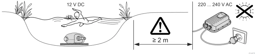
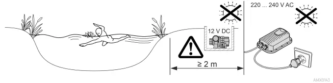
The power supply carries dangerous electrical voltage and must not be placed directly near water. Otherwise, there is a risk of serious injury or death from electric shock.
The transformer is subject to dangerous voltage and must not be installed directly adjacent to the water. Otherwise there is a risk of severe injuries or death by electrocution.
Install the power supply in a flood-protected position at least 2 m (6.6 ft) from the water.
![]() CAUTION
CAUTION
Rotating components in the area of the intake connection and the pressure connection. Reaching into the connections can lead to injuries.
Please note in particular: If a unit has stopped due to overload, it can start up unexpectedly!
- Do not reach into the opening of the inlet connection or outlet connection while the power plug is connected.
- If the connections are freely accessible, e.g. if no hoses are connected, secure the connections with a finger guard. The finger guard is available as an accessory
NOTE
Electrical screw connections …
- must always be hand-tightened to ensure safe contact and to comply with the degree of protection specified in the technical data.
- are protected against splashing water, but must not be immersed or submerged in water.
NOTE
If the pump is used for conveying excessively muddy water, the impeller unit will be subject to increased wear and will require earlier replacement.
- Thoroughly clean the pond or pool before installing the pump.
- Install the pump at a raised level above the bottom of the pond. This reduces intake of muddy water.
![]() Avoid direct sunlight when the components of the unit are not immersed, as this can cause them to heat up considerably. Use a protective cover if necessary.
Avoid direct sunlight when the components of the unit are not immersed, as this can cause them to heat up considerably. Use a protective cover if necessary.
Submerged installation of the unit
Connection
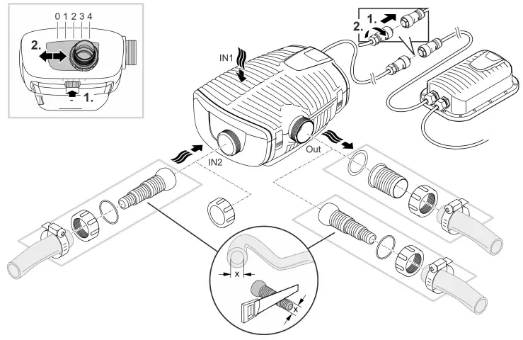
Connect the pump as required by the desired installation variant. (→ Installation variants) Do not plug the power plug into the outlet yet!
Installation
- Position the pump horizontally on a firm, mud-free surface.
- Ensure that the pump is securely positioned.
- Only operate the pump when it is fully submerged.
 A pull rope allows you to simply pull the pump out of the water.
- Pull the pull rope through the round openings on the bottom pan of the filter and make a knot.
Dry installation of the unit
For dry installation, install the pump without a filter casing.
Conversion
Connection
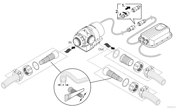
Do not plug the power plug into the outlet yet!
Installation
- Position the pump horizontally on a firm, mud-free surface.
- Ensure that the pump is securely positioned.
Commissioning/start-up
NOTE
The unit will be destroyed if it is operated with a dimmer. It contains sensitive electrical components.
Do not connect the unit to a dimmable power supply.
NOTE
Never allow the pump to run dry. Otherwise the pump will be destroyed.
Only operate pump while it is submerged.
![]() A brand-new pump will only reach its maximum capacity after several hours of operation.
A brand-new pump will only reach its maximum capacity after several hours of operation.
Switching ON/OFF
- Switching on: Plug the power plug into the outlet.
- The unit switches on immediately.
- Switching off: Pull the power plug from the outlet
Environmental Function Control (EFC)
When started up, the pump automatically performs a pre-programmed self test (Environmental Function Control (EFC)). The pump detects if it is running dry / blocked or submerged. The pump switches off automatically after approx. 90 seconds if it runs dry/is blocked. In the event of a malfunction, disconnect the power supply and “flood the pump” or remove the obstacle. Afterwards, the unit can be restarted.
Maintenance and cleaning
CAUTION
Risk of injury due to unforeseeable start-up. A temperature monitor switches the unit off automatically in the event of overload and on again once it has cooled down.
Disconnect the power plug before carrying out any work on the unit.
NOTE
Do not use aggressive cleaning agents or chemical solutions. These agents can damage the housing, impair the function of the device and harm animals, plants and the environment.
Clean the unit with clean water and a soft brush or sponge wherever possible. Remove stubborn dirt with the aid of the recommended cleaning agents.
Cleaning the unit
![]() Clean the unit as required, but at least twice a year.
Clean the unit as required, but at least twice a year.
- When cleaning the pump, pay particular attention to the impeller unit and the pump casing.
- Recommended cleaning agent for removing stubborn limescale deposits:
- Pump cleaning agent PumpClean from OASE.
- Vinegar- and chlorine-free household cleaning agent.
- After cleaning, thoroughly rinse all parts in clean water.
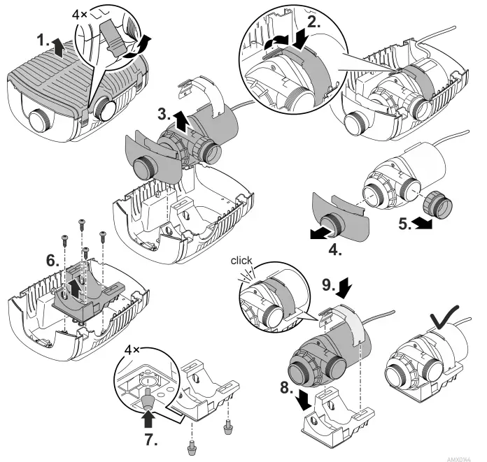
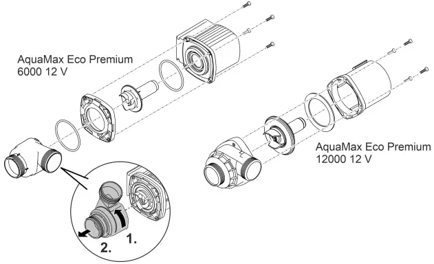
Pump disassembly/cleaning
- Pull the power plug and remove all connections.
- Dismantle the unit as shown in the figure.
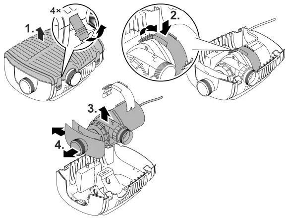
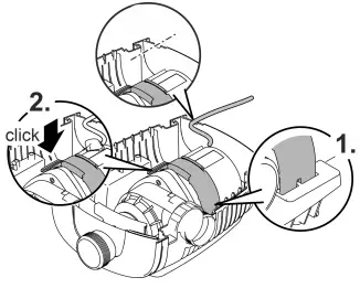
- Reassemble the unit in reverse order.
- During assembly check that
- the clamp fastening the pump in the holder has securely engaged.
- the connection cable is guided out through the groove on the casing and is not significantly kinked or pinched.
Cleaning/replacing the impeller unit
- Dismantle the pump as shown in the figure.
- Clean the components with a brush under clear water.
- Check all components for damage. Replace damaged or worn components.
- Reassemble the pump in reverse order.
Storage/overwintering
The unit is frost resistant to minus 20 °C. Should you store the unit outside of the pond, clean it thoroughly with a soft brush and water, check it for damage, then store immersed in water. Do not immerse the power plug in water!
Troubleshooting
| Malfunction | Cause | Remedy |
| The pump does not start | No power supply | Check power supply |
| Supply lines kinked | Route the supply lines without kinks | |
| Supply lines clogged | Check/clean supply lines | |
| The impeller unit is blocked | Remove block, check impeller unit for ease of movement | |
| Pump does not transport liquid Insufficient conveyed volume | Filter casing clogged | Clean filter pans |
| Excessive loss in the supply lines | Reduce hose lengths to the necessary minimum, remove unnecessary connection parts | |
| Impeller unit is running sluggishly | Check impeller unit for ease of movement | |
| Pump switches off after a short running period | Water is heavily soiled | Clean pump |
| The impeller unit is blocked | Remove block, check impeller unit for ease of movement | |
| Pump has run dry | Check/clean supply lines | |
| Water temperature too high | Adhere to the maximum permissible water temperature. (→ Technical data) |
Technical data
| Switching power pack | 100 VA / 12 V DC | ||
| Primary Mains voltage | V AC | 220 … 240 | |
| Power frequency | Hz | 50/60 | |
| Max. power consumption | W | 110 | |
| Cable length | m | 2.0 | |
| Secondary Output voltage | V DC | 12 | |
| Max. output current | A | 8.5 | |
| Cable length | m | 0.5 | |
| Protection type | IP44 | ||
| Protection class | II | ||
| Ambient temperature | °C | -10 … +35 | |
| Dimensions (L × W × H) | mm | 231 × 148 × 68 | |
| Weight | kg | 2.3 | |
| AquaMax Eco Premium | 6000 / 12 V | 12000 / 12 V | |
| Connection voltage | V DC | 12 | 12 |
| Max. current consumption | A | 4.0 | 8.5 |
| Max. power consumption | W | 45 | 95 |
| Max. delivery rate | l/h | 6000 | 11400 |
| Max. pumping head | m | 3.2 | 3.2 |
| Protection type Pump | IP68 | IP68 | |
| Connection | IPX4 | IPX4 | |
| Max. immersion depth | m | 4 | 4 |
| Suction side Thread | G2 | G2 | |
| Hose connection | mm | 25, 32, 38 | 25, 32, 38 |
| Pressure side Thread | G2 | G2 | |
| Hose connection | mm | 25, 32, 38, 50 | 25, 32, 38, 50 |
| Max. grain size of coarse dirt | mm | 10 | 11 |
| Filter inlet area | cm² | 1000 | 1000 |
| Water temperature (sub- During operation | °C | (→ Permissible | water values) |
| merged installation) Outside of operation | °C | -20 … +35 | -20 … +35 |
| Ambient temperature During operation and (dry installation) natural convection | °C | +4 … +30 | +4 … +30 |
| During operation and forced cooling | °C | +4 … +40 | +4 … +40 |
| Dimensions Length | mm | 340 | 340 |
| Width | mm | 280 | 280 |
| Height | mm | 165 | 165 |
| Length of connection cable | m | 8 | 8 |
| Weight | kg | 8.7 | 10.5 |
Permissible water values
| Type | Fresh water | Pool water | Salt water |
| pH value | 6.8 … 8.5 | 7.2 … 8.3 | 7.5 … 8.5 EN |
| Hardness | DH 8 … 15 | 8 … 15 | 20 … 30 |
| Free chlorine | mg/l <0.3 | <0.6 | <0.3 |
| Chloride content | mg/l <250 | <250 | <22000 |
| Salt content | % <0.4 | <0.4 | <4 |
| Overall dry residue | mg/l <50 | <50 | <50 |
| Temperature | °F +39.2 … +95 | +39.2 … +86 | +39.2 … +82.4 |
Wear parts
Impeller unit
Disposal
NOTE
Do not dispose of this unit with domestic waste.
- Dispose of the unit by using the return system provided for this purpose.
- Should you have questions, please contact your local disposal company. They will give you instructions on how to dispose of your unit properly.
- Disable the unit by cutting off the cables.