![]() OPTIMA – WINNER
OPTIMA – WINNER
INSTALLATION AND MAINTENANCE MANUAL
![]()
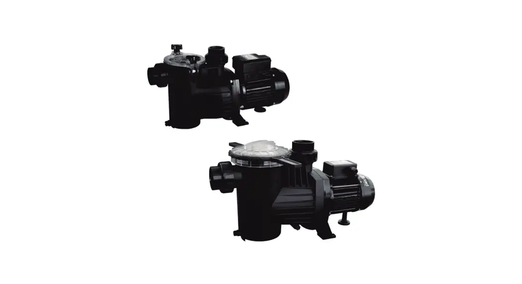
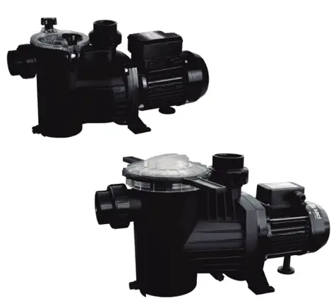
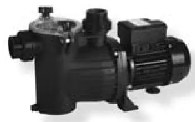
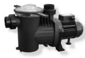
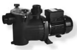
OPTIMA Swimming Pool Pump and Filter
OPTIMA – WINNER
DECLARATION OF CONFORMITY CE:
We, BOMBAS SACI, S.A., CL/Can Cabanyes, 50-58 – Pol. Ind. Circuit de Catalunya – 08403 – Granollers – SPAIN, state that under our exclusive responsibility the products referred to in this statement comply with the following directives and subsequent revisions:
- 2004/108/EC (Electromagnetic Compatibility Directive)
- 2006/95/EC (Low Voltage Directive)
- 2009/125/EC (Ecologic Design Directive)
- 2011/65/EU (Dangerous Substances Directive) and that they also comply with the following regulations:
- EN 60335-1 (Household and Similar Electrical Appliances – Safety)
- EN 60335-2-41 (Particular Requirements for Pumps)

David Ferré Ferrer
EXECUTIVE
(Instructions based on Spanish)
SAFETY PRECAUTIONS
This symbol together with one of the following words “Warning” or “Danger” indicates the risk level deriving from failure to observe the prescribed safety precautions:![]() DANGER risk of electric shock (Warns that failure to observe the precautions involves a risk of electric shock)
DANGER risk of electric shock (Warns that failure to observe the precautions involves a risk of electric shock)![]() DANGER (Warns that failure to observe the precautions involves a risk of damage to persons or things)
DANGER (Warns that failure to observe the precautions involves a risk of damage to persons or things)![]() WARNING (Warns that failure to observe the precautions involves a risk of damaging the pump or the instalation)
WARNING (Warns that failure to observe the precautions involves a risk of damaging the pump or the instalation)
WARNINGS
![]() Before carrying out the installation, please read this instruction manual carefully.
Before carrying out the installation, please read this instruction manual carefully.
It is essential that both the electrical installation and the connections are performed by qualified personnel, who possess the required technical expertise required by the specific safety regulations for the project, installation and maintenance of the technical installations for the country where the product is to be installed.
Any non-compliance with the safety regulations, in addition to being a danger to personnel and causing damage to the equipment, will cancel all rights to interventions covered by the guarantee.
- The device is not designed for use by persons (including children) with physical, sensory or mental capabilities, or lack of experience and knowledge, unless they are supervised and instructed by a person responsible for their safety.
- Children should be supervised to ensure they do not play with the appliance.
APPLICATIONS AND USE
Self-induction electric pump for swimming pools, incorporating large capacity pre-filter with high filtration capability. Transparent, polycarbonate filter cover allowing easy observation of the inside of the pre-filter basket. Our pumps have been developed for continuous operation and the materials used in their manufacture are subjected to strict controls and are rigorously verified.
The machine has been designed to pump water that is free from explosive substances, with a density equivalent to 1000 Kg/m 3 and a kinematic viscosity of 1 mm 2 /s, as well as chemically non-aggressive liquids. It has no uses other than the one previously described.
TECHNICAL DATA AND LIMITATIONS OF USE
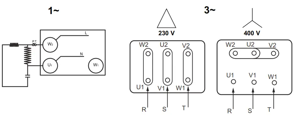
| Power supply voltage: | Single-phase, 230 V, 50/60 Hz. Three-phase, 230 – 400 V, 50/60 Hz. See data plate |
| Motor Protection: | “IP 55” |
| Insulation class: | Class “F” |
| MAXIMUM ENVIRONMENTAL TEMP.: | +40ºC |
| MAXIMUM PUMPED LIQUID TEMP.: | +40ºC |
TRANSPORT
Do not subject the products to unnecessary bumps and knocks.
When lifting and transporting the unit, use machines and tools that have been designed for this purpose, using the pallet supplied as standard (if present).
STORAGE
All the pumps should be stored in a sheltered, dry, dust-free place, with regulated air-moisture levels when possible.
The pumps are supplied in their original packaging, where they must remain until assembly.If not, keep the suction and discharge ports closed.
INSTALLATION
General![]() The pump should be installed as close as possible to the level of water, leaving a minimum of two metres to the swimming pool edge in accordance with IEC publication No. 364 in a horizontal position, in order to obtain minimum run length in suction and a reduction of load losses.
The pump should be installed as close as possible to the level of water, leaving a minimum of two metres to the swimming pool edge in accordance with IEC publication No. 364 in a horizontal position, in order to obtain minimum run length in suction and a reduction of load losses.
Sufficient space should be allowed for removing to pre-filter basket for cleaning and re-fitting.
The pump should be installed on a solid, very smooth surface. It is necessary to perfectly fit the pump through the two holes provided for this purpose in the support base by means of two screws or other similar methods to prevent any possible noise or vibration that could adversely affect the pump operation.
The pump should not be installed at a geometric height of more than 3.5 metres above the water level.
In order to obtain optimum pump self-priming, it should be installed at a maximum of 2.5 metres above the water level.
The pump should be protected from any possible flooding and correct ventilation should be ensured, but without risking the effects of freezing. In the case of outside installation, the pump should be protected from rain and a power supply cable in accordance with EEC standards, type H07-Requirement Number-F (in accordance with VDE 0250) should be installed. The pump is normally supplied without an electric power cable. In this case the pump test cables can be seen to be cut at the outlet of the motor junction box. These cables must be replaced by a suitable electric hose in accordance with the legislation in force in each country.
In the case of being installed a fibre housing, whether buried or half-buried, sufficient air flow should be guaranteed to generate correct ventilation that prevents the maximum interior temperature from exceeding 40ºC.
Assembling the Piping![]() We recommend the installation of cut-off valves in both pump suction and impulsion so that the pump may be removed from the installation without having to empty the whole circuit first.
We recommend the installation of cut-off valves in both pump suction and impulsion so that the pump may be removed from the installation without having to empty the whole circuit first.
The suction piping should be at least the same diameter as the pump connection, and it is also recommended that the impulsion piping should also be the same diameter as the pump connection.
The suction piping should be assembled with a slight inclination towards the pump to prevent air pockets forming inside.
It is very important that both the suction and impulsion piping are independently supported and correctly fixed in place so that the pump does not have to support their weight nor the vibration produced by the water flow though them. In a situation where a long length of impulsion piping is used, we recommend the installation of a check valve to prevent the water hammer produced by the return of the water causing any damage when the pump stops. If flexible piping is employed, it should be the non-compressible type.
When making the connections to the pump, totally clean connections should always be used, with the thread in perfect conditions and leak-tightness should be obtained only through the use of Teflon tape, (glues or similar products should not be employed). These connection should be slowly tightened, with special care not to strip the internal thread of the pump by over-tightening.
ELECTRICAL CONNECTION
![]() Before carrying out any maintenance on the electrical part of the motor, it should be disconnected from the electricity supply.
Before carrying out any maintenance on the electrical part of the motor, it should be disconnected from the electricity supply.
System protection should be based on a differential breaker (Ifn = 30 mA). A GOOD EARTH CONNECTION MUST BE MADE WHENEVER POSSIBLE. The earth terminal, in particular, must be connected to the yellow/green conductor of the supply cable. An earth conductor that is longer than the phase conductors must also be used so as to prevent it from being the first to disconnect if pulled.
All our single-phase motors incorporate thermal protection that will disconnect the pump if the motor temperature increases due to an overload and will then connect the electricity supply again once the temperature has dropped to within normal levels again.
For three-phase versions, the user should provide appropriate protection in accordance with current regulations.
It is essential to connect the pump to a suitable ground.
The following diagram, should be used when making the electrical connections to the pump terminals.
Use is only permitted if the electric installation has safety protection systems in accordance with personal safety regulations in force in the country where the product is to be installed.
CHECKS PRIOR TO PUTTING INTO SERVICE
![]() THE PUMP SHOULD NEVER BE ALLOWED TO OPERATE OFF LOAD
THE PUMP SHOULD NEVER BE ALLOWED TO OPERATE OFF LOAD
Check that the voltage and frequency of the incoming mains electricity supply correspond to those on the pump’s specification plate.
Unscrew the transparent pre-filter cover and fill the pre-filter with water until the water level reaches the suction hole.
Replace the pre-filter cover and hand-tighten only, ensuring that it is fully tightened.
Check the pump shaft is able to freely rotate.
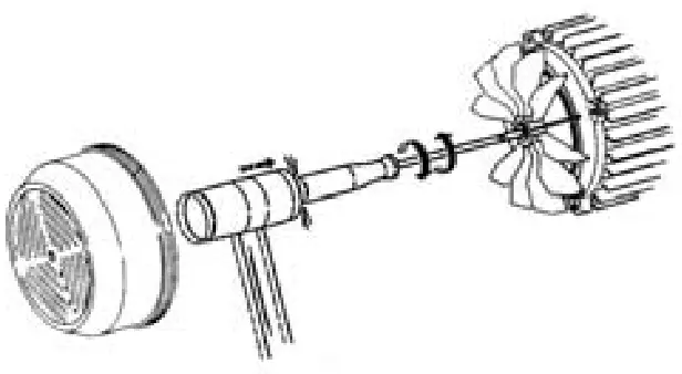
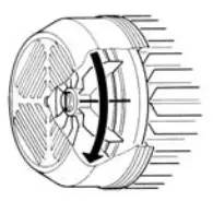
Check the that the direction of motor rotation corresponds with that indicated on the specification plate (the fan should rotate in a CLOCKWISE DIRECTION, when viewed from the rear of the motor. If the motor is three-phase and it is observed that it is rotating in the opposite direction, then two of the supply phases should be inverted at the protection panel.
PUTTING INTO SERVICE
Open all valves, both suction and impulsion, and switch on the pump.![]() Wait a reasonable time for the pump and suction piping to self-prime. If this takes too long, then the priming process should be repeated.
Wait a reasonable time for the pump and suction piping to self-prime. If this takes too long, then the priming process should be repeated.
Once the pump has correctly self-primed and the pre-filter body is seen to be full of water, the motor current should be checked and the thermal relay adjusted appropriately.
MAINTENANCE, DISMANTLING AND RECYCLING
![]() The most important maintenance operation is that of keeping the pre-filter basket clean, and this filter state check should be performed after each filtration operation and especially after bottom-cleaning. The procedure is as follows:
The most important maintenance operation is that of keeping the pre-filter basket clean, and this filter state check should be performed after each filtration operation and especially after bottom-cleaning. The procedure is as follows:
Disconnect the electricity supply to the pump. Close the suction and impulsion valves to the pump. Open the pre-filter cover, remove the basket and clean it. Once it is clean, replace it, but before closing, check the condition of the pump body thread, pre-filter cover and the O-ring, cleaning them only with water, and where necessary apply a light coating of neutral Vaseline.
The pump should only be dismantled by qualified personnel who hold the technical qualifications required under the technical safety regulations of the country where the product is located.
This product and its components must be disposed of in accordance with environmental regulations. Use local public or private waste-collection systems.
Under no circumstances should chlorine tablets be placed in the pre-filter basket.
The special key that is supplied to OPEN the pre-filter cover, should never be employed to close it.![]() When there is a frost risk, or when the pump is to remain off for any significant length of time, then it should be emptied. This is accomplished by removing the two emptying plugs on the lower part of the pump body.
When there is a frost risk, or when the pump is to remain off for any significant length of time, then it should be emptied. This is accomplished by removing the two emptying plugs on the lower part of the pump body.
Apart from what has been stated above, our pumps do not require any other maintenance operations since the bearings have been dimensioned and lubricated for life.
POSSIBLE FAULTS, THEIR CAUSES AND SOLUTIONS
| FAULTS | CAUSES | SOLUTIONS |
| • The pump will not prime | • The pump has not been primed • Air entering by the suction piping • Air entering via the mechanical seal • Incorrectly closed pre-filter cover • Excessive suction height • Inverted motor rotation • Incorrect voltage | • Fill the pre-filter with water. • Check the connections and piping. • Replace the mechanical seal. • Close correctly. • Install at a suitable height. • Invert two of the motor phases. • Check the plate voltage. |
| • The pump provides a poor flow rate | • Air entering by the suction piping. • Excessive suction height. • Inverted motor rotation. • Incorrect voltage. • Blocked • Suction piping diameter is less than that required. • Impulsion closed or blocked. | • Check the connections and piping. • Install at a suitable height. • Invert two of the motor phases. • Check the plate voltage. • Clean the pre-filter basket. • Correctly dimension the suction piping. • Open the valve and check the sand filter condition. |
| • The pump makes a lot of noise | • Suction piping diameter is less than that required. • The pump or piping has not been correctly secured. • Inverted motor rotation | • Correctly dimension the suction piping. • Recheck the pump and piping securing methods so that they are separate. • Invert two of the motor phases |
| • The pump Will not start | • Lack of mains supply. • Breaker operation. • Incorrect voltage. • Motor jammed. | • Check the voltage and fuses. • Check and reset breaker. • Check the plate voltage. • Consult the Official Technical Service. |
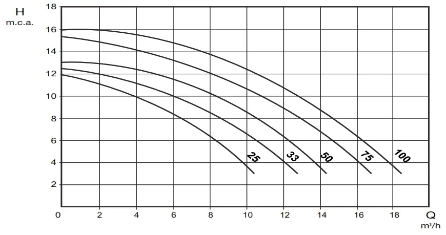
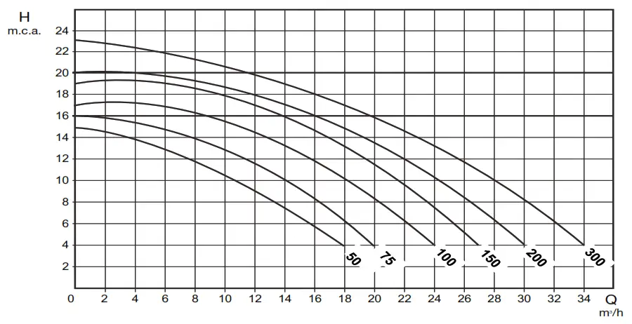
 CHARACTERISTICS
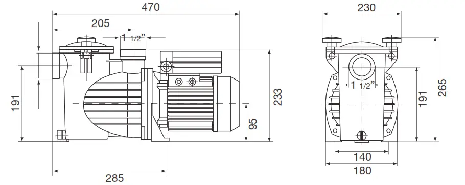
DIMENSIONS
| Tipo/Type | “Kg” | PVC linCg |
| 25 | 12. | 50 |
| 33 | 12. | 50 |
| 50 | 12. | 50 |
| 75 | 13. | 50 |
| 100 | 13. | 50 |
CHARACTERISTICS
DIMENSIONS
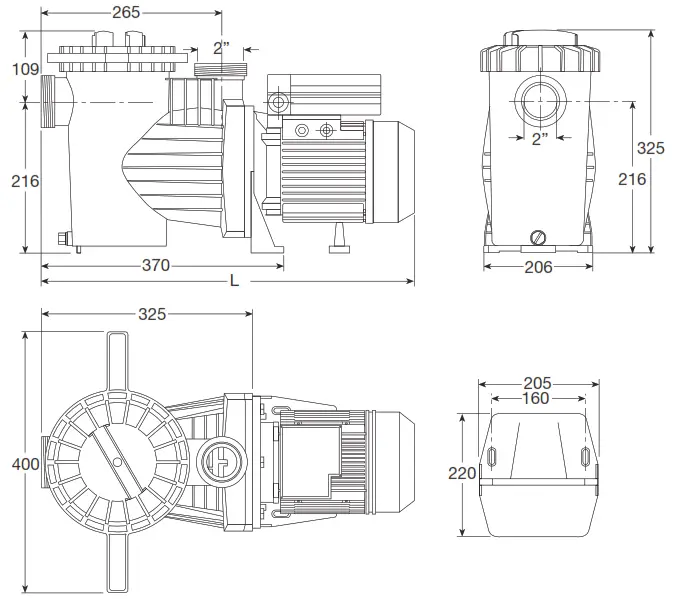
| Tipo/Type | “L” | “Kg” |
| 50 M | 550 | 10,9 |
| 50 T | 550 | 10,9 |
| 75 M | 550 | 11,4 |
| 75 T | 550 | 10,9 |
| 100 M | 550 | 12,4 |
| 100 T | 550 | 12,4 |
| 150 M | 580 | 15,4 |
| 150 T | 580 | 13,9 |
| 200 M | 650 | 16,9 |
| 200 T | 575 | 15,4 |
| 300 M | 650 | 20,4 |
| 300 T | 650 | 17,4 |
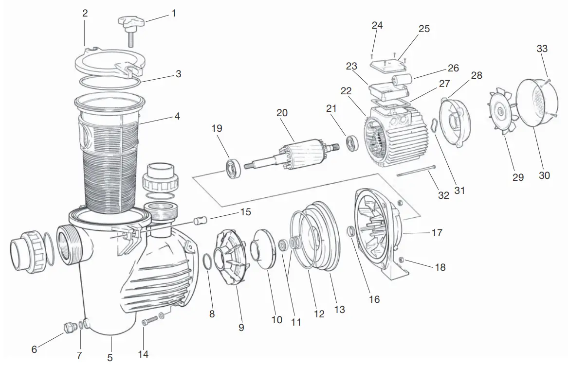
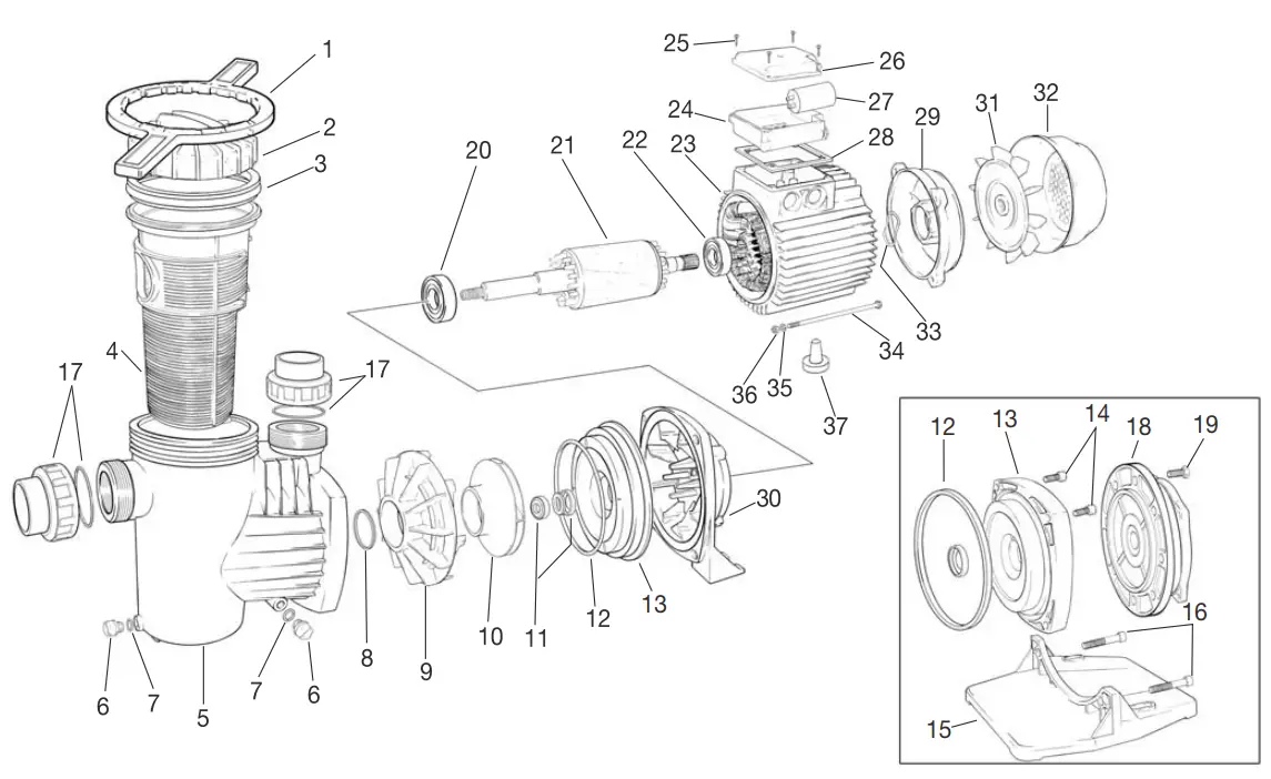
| 1 | PRE-FILTER HANDLE |
| 2 | PRE-FILTER COVER |
| 3 | PRE-FILTER JOINT |
| 4 | PRE-FILTER BASKET |
| 5 | PUMP BODY |
| 6 | DRAINING PLUG |
| 7 | DRAINING PLUG O-RING |
| 8 | DIFFUSER JOINT |
| 9 | DIFFUSER |
| 10 | IMPELLER |
| 11 | MECHANICAL SEAL |
| 12 | PUMP BODY LID O-RING |
| 13 | PUMP BODY LID |
| 14 | PUMP BODY SECURING SCREW |
| 15 | PRE-FILTER HANDLE CILINDER |
| 16 | FRONT IP-55 PROTECTION SEAL |
| 17 | PUMP SUPPORT |
| 18 | PUMP BODY SECURING NUT |
| 19 | FRONT BALL BEARING |
| 20 | SHAFT WITH ROTOR |
| 21 | BACK BALL BEARING |
| 22 | MOTOR CASING |
| 23 | TERMINAL BOX |
| 24 | TERMINAL BOX SCREW |
| 25 | TERMINAL BOX COVER |
| 26 | CAPACITOR |
| 27 | TERMINAL BOX GASKET |
| 28 | BACK MOTOR COVER |
| 29 | FAN |
| 30 | FAN COVER |
| 31 | THRUST WASHER |
| 32 | TIE ROD |
| 33 | FAN COVER SCREW |
| 1 | KEY |
| 2 | PRE-FILTER COVER |
| 3 | PRE-FILTER JOINT |
| 4 | PRE-FILTER BASKET |
| 5 | PUMP BODY |
| 6 | DRAINING PLUG |
| 7 | DRAINING PLUG O-RING |
| 8 | DIFFUSER JOINT |
| 9 | DIFFUSER |
| 10 | IMPELLER |
| 11 | MECHANICAL SEAL |
| 12 | PUMP BODY LID O-RING |
| 13 | PUMP BODY LID |
| 14 | SUPERIOR PUMP BODY SECURING SCREW |
| 15 | PUMP BASE |
| 16 | PUMP BASE SECURING SCREW |
| 17 | COUPLINGS KIT |
| 18 | FRONT MOTOR COVER |
| 19 | MOTOR SECURING SCREW |
| 20 | FRONT BALL BEARING |
| 21 | SHAFT WITH ROTOR |
| 22 | BACK BALL BEARING |
| 23 | MOTOR CASING |
| 24 | TERMINAL BOX |
| 25 | TERMINAL BOX SCREW |
| 26 | TERMINAL BOX COVER |
| 27 | CAPACITOR |
| 28 | TERMINAL BOX GASKET |
| 29 | BACK MOTOR COVER |
| 30 | PUMP SUPPORT |
| 31 | FAN |
| 32 | FAN COVER |
| 33 | THRUST WASHER |
| 34 | TIE ROD |
| 35 | TIE ROD WASHER |
| 36 | TIE ROD NUT |
| 37 | FOOT MOTOR |
RATINGS
| POTENCIA/POWER | Q | H | H max | H min | ||
| 0.25 HP | 0,5 | 10 | 12 | 4 | 12,5 | 3 |
| 0.33 HP | 2 | 12 | 12 | 4 | 13 | 3 |
| 0.5 HP | 5 | 14 | 12 | 4 | 14,5 | 3 |
| 0.75 HP | 4,2 | 16 | 14 | 4 | 14,5 | 3 |
| 1 HP | 7,6 | 18 | 14 | 4 | 15,5 | 3 |
| POTENCIA/POWER | Q | H | H max | H min | ||
| 0.5 HP | 8,4 | 17,5 | 12 | 4 | 14,9 | 3 |
| 0.75 HP | 7,9 | 19,5 | 14 | 4 | 16,1 | 3 |
| 1 HP | 8,7 | 23,2 | 16 | 4 | 16,3 | 3 |
| 1.5 HP | 10 | 27,7 | 18 | 4 | 20 | 3 |
| 2 HP | 12 | 29 | 18 | 6 | 20 | 5 |
| 3 HP | 12 | 33 | 21 | 6 | 24 | 5 |
AMP PROTECTION
| POTENCIA/POWER | II 230 V 50/60 Hz | III 230 V 50/60 Hz | III 400 V 50/60 Hz |
| 0.25 HP | 4 | – | – |
| 0.33 HP | 4 | – | – |
| 0.5 HP | 4 | – | – |
| 0.75 HP | 6 | 4 | 2 |
| 1 HP | 6 | 4 | 4 |
| POTENCIA/POWER | II 230 V 50/60 Hz | III 230 V 50/60 Hz | III 400 V 50/60 Hz |
| 0.5 HP | 4 | 4 | 2 |
| 0.75 HP | 6 | 4 | 2 |
| 1 HP | 6 | 4 | 4 |
| 1.5 HP | 8 | 6 | 4 |
| 2 HP | 10 | 8 | 4 |
| 3 HP | 16 | 10 | 6 |
14 – TEST CERTIFICATE
All of our pumps pass strict quality control, so we are able to guarantee their optimal operation and reliability.
Absolutely ALL of the pumps are tested on out assembly lines with water under normal working conditions and with the most modern measurement systems. As a sign of this, along with the present manual, we attach a “Test certificate” adhesive label.
If you should note any fault or shortcoming, you must report the details of the type of fault, the pump model and the serial no. so that we can check the cause of the problem and thus be able to continue offering you the best quality.
![]() Can Cabanyes, 50-58 – Pol. Ind. Circuit de Catalunya
Can Cabanyes, 50-58 – Pol. Ind. Circuit de Catalunya
08403 Granollers Spain
Tel. (+34) 933 842 351
Fax (+34) 933 842 900
www.sacipumps.com
[email protected]


