![]() C.H. pump controller
C.H. pump controller
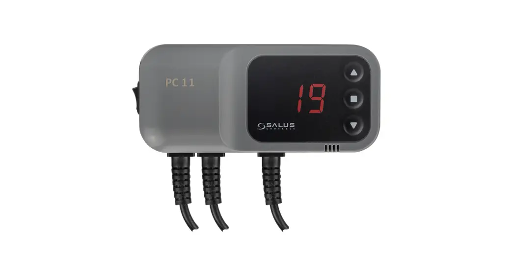
Model: PC11
User Manual
Introduction
The PC11 controller is designed to control the water pump in C.H. systems. The controller’s task is to start the pump when the temperature will exceed the desired value and turn it off when the boiler will cool down. It prevents unnecessary pump operation and extends its service life, which allows also to save electricity. Savings depends on the boiler’s utilization rate, up to 60%. Thanks to this, pump reliability increases and heating costs are lower.
Product Compliance
This product complies with the essential requirements and other relevant provisions of the following EU Directives: EMC 2014/30/EU, RoHS 2011/65/EU.
 Safety Information
Use in accordance with national and EU regulations. Use the device as intended, keeping it in dry condition. Product for indoor use only. Installation must be carried out by a qualified person in accordance with national and EU regulations.
Before carrying out any activities related to the power supply (connecting wires, device installing, etc.), make sure that the main power is not connected to the controller! Incorrect wiring connections may cause device damage.
Controller description
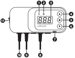
| 1. Power supply indicator 2. C.H. pump operation indicator 3. Display 4. Increasing setpoint temperature or value 5. Menu button 6. Decreasing setpoint temperature or value | 7. Sound alarmed 8. Temperature sensor 9. Pump power supply 10. Controller power supply 11. ON/OFF the power supply switch |
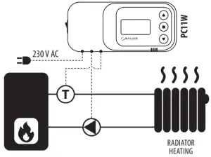
Wiring diagram
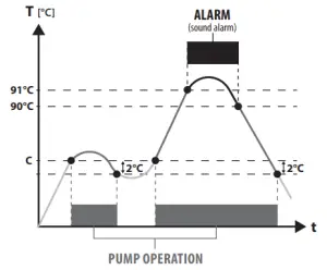
Principle of operation
C – pump start temperature
Controller operation
Setpoint temperature is changed by pressing ![]() a button – the display should indicate a flashing „C” letter. At this point, it is possible to change the desired setpoint temperature using
a button – the display should indicate a flashing „C” letter. At this point, it is possible to change the desired setpoint temperature using ![]() or
or![]() buttons. After a few seconds, the controller will go into operating mode and display the current boiler temperature.
buttons. After a few seconds, the controller will go into operating mode and display the current boiler temperature.
Manual mode
This function allows checking if the connected pump is working correctly. The pump will be turned on after pressing buttons![]() and
and ![]() Pressing these buttons again will turn off the pump.
Pressing these buttons again will turn off the pump.
Hysteresis
This is the difference between the temperature of the pump start and the temperature of return to standby. The controller has a constant hysteresis of 2°C. For example, after setting the setpoint temperature at 50°C, the pump will be turned on after exceeding 50°C and will be turned off when the temperature will drop to 48°C.
Additional functions
Controller has an „anti-stop” function which protects the pump against limescale when there is no heating season. The pump is turned on every 14 days for 15 seconds.
Additional protection is the frost protection function, which runs the pump permanently when the temperature on the sensor drops below 5°C.
Alarm
The controller is equipped with a sound alarm that signals too high a temperature on the boiler (above 90°C).
Technical specification
| Power supply | 230 V / 50Hz ±10% |
| Power consumption | 2 W |
| Ambient temperature | -10 to 50°C |
| Max load of the pump output | 6 A |
| Temperature measurement range | 0 to 99°C |
| Setpoint temperature range | 5 to 80°C |
| Sensor temperature range | -10 to 120°C |
| Sensor cable length | 1,2 m |
DISTRIBUTOR OF SALUS CONTROLS:
QL CONTROLS Sp. z o.o., Sp. k.
Rolna 4
43-262 Kobielice
Poland
www.salus-controls.eu
Maintaining a policy of continuous product development SALUS Controls plc reserve the right to change specification, design, and materials of products listed in this brochure without prior notice.![]()
![]() Pump controller for C.H. or H.W.
Pump controller for C.H. or H.W.
Model: PC11W
User Manual
Introduction
PC11W controller is designed to control the water pump in the central heating system or pump of the hot water tank. It can be used also as a safety thermostat. The controller will turn on r turn off the pump depending on the sensor temperatures. The pump is running after exceeding the setpoint temperature „C” set by the user and it will stop after exceeding setpoint temperature „U”.
Product Compliance
This product complies with the essential requirements and other relevant provisions of the following EU Directives: EMC 2014/30/EU, RoHS 2011/65/EU.
Safety Information
Use in accordance with national and EU regulations. Use the device as intended, keeping it in dry condition. Product for indoor use only. Installation must be carried out by a qualified person in accordance with national and EU regulations.
Before carrying out any activities related to the power supply (connecting wires, device installing, etc.), make sure that the main power is not connected to the controller! Incorrect wiring connections may cause device damage.
Controller description
| 1. Power supply indicator 2. Pump operation indicator 3. Display 4. Increasing setpoint temperature or value 5. Menu button 6. Decreasing setpoint temperature or value | 7. Sound alarmed 8. Temperature sensor 9. Pump power supply 10. Controller power supply 11. ON/OFF power supply switch |
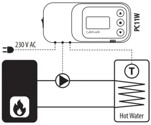
Wiring diagrams – examples
- CENTRAL HEATING PUMP CONTROLNOTE! The „U” parameter should be set to the maximum value. The pump will be turned on when the temperature sensor exceeds the value of the „C” parameter.

- HOT WATER PUMP CONTROL OR WORK AS A SAFETY THERMOSTATNOTE! The „C” parameter should be set to the minimum value. The pump will be turned off when the temperature sensor exceeds the value of the „U” parameter.
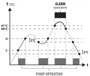
Principle of operation
U – above this temperature pump is turned OFF
C – above this temperature pump is turned OFF
Controller operation
The setpoint temperature of the pump start can be changed by pressing the![]() button (menu option). On the display appears flashing the „C” letter. At this point, the „C” setpoint temperature can be changed with
button (menu option). On the display appears flashing the „C” letter. At this point, the „C” setpoint temperature can be changed with![]() or
or![]() buttons. After a few seconds controller will go into operating mode and display the current temperature.
buttons. After a few seconds controller will go into operating mode and display the current temperature.
The setpoint temperature of the pump stops can e changed by pressing the twice ![]() button (menu option). „U” parameter is the next parameter after „C”. On the display appears flashing the „U” letter. At this point, the „U” setpoint temperature can be changed with
button (menu option). „U” parameter is the next parameter after „C”. On the display appears flashing the „U” letter. At this point, the „U” setpoint temperature can be changed with![]() or
or![]() buttons. After a few seconds controller will go into operating mode and display the current temperature.
buttons. After a few seconds controller will go into operating mode and display the current temperature.
Manual mode
This function allows checking if the connected pump is working correctly. The pump will be turned on after pressing buttons![]() and
and ![]() . Pressing these buttons again will turn off the pump.
. Pressing these buttons again will turn off the pump.
Hysteresis
This is the difference between the temperature of the pump start and the temperature of return to standby. Controller has a constant hysteresis of 2°C. For example:
- When the „C” parameter is set to 30°C, then the pump will turn on after exceeding 30°C and turn off when the temperature will drop to 28°C.
- When the „U” parameter is set to 50°C, then the pump will turn off after exceeding 50°C and turn on when the temperature will drop to 48°C.
Additional functions
The controller has an „anti-stop” function which protects the pump against limescale when there is no heating season. The pump is turned on every 14 days for 15 seconds.
Additional protection is the frost protection function, which runs the pump permanently when the temperature on the sensor drops below 5°C.
Alarm
The controller is equipped with a sound alarm which signals too high a temperature on the boiler (above 90°C).
Technical specification
| Power supply | 230 V / 50Hz ±10% |
| Power consumption | 2 W |
| Ambient temperature | -10 to 50°C |
| Max load of the pump output | 6 AM |
| Temperature measurement range | 0 to 99°C |
| Setpoint temperature range | 5 to 80°C |
| Sensor temperature range | -10 to 120°C |
| Sensor cable length | 1,2 m |
DISTRIBUTOR OF SALUS CONTROLS:
QL CONTROLS Sp. z o.o., Sp. k.
Rolna 4
43-262 Kobielice
Poland
www.salus-controls.eu
Maintaining a policy of continuous product development SALUS Controls plc reserve the right to change specification, design, and materials of products listed in this brochure without prior notice.
![]()


