![]() inspired access
inspired access
Installation guide
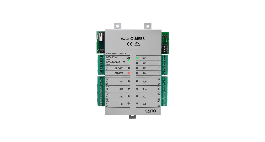
XS4 Controller
The expansion board unit provides multi-relay switchable output management to external systems such as lift floor level access, multi shutter and barrier systems, machine switching, and more.
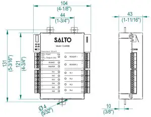
Mechanical Installation
 *Note: In order to comply with EN 50131-3:2009, the two highlighted openings can’t be used. | 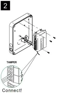 | 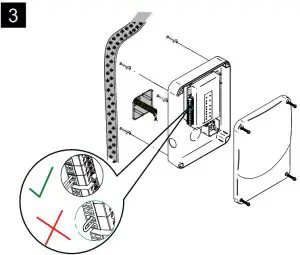 |
Note: Follow the same connection model, using the CU tamper input, when using a third-party electric box equipped with a tamper opening detection.
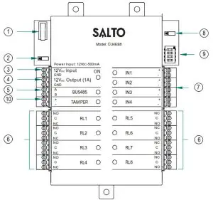
- Physical tamper switch to be operated by external electric box models.
- BUS RS485 Terminal Resistor must be in the ON position when the CU is connected at the end of the BUS.
- Power Input.
- Power Output: This output is directly connected to the power Input port protected by a 1A fuse.
- BUS485.
- Relay Connections: Please take into account the max. load restrictions(2A-30VDC). Use the provided varistor if an inductive load is used.
- Inputs: Installer must identify the bridge cable needed depending on the input configuration.
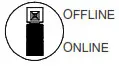
- Online/Offline jumper: Configure the unit to work as an offline device.
Dip switch: - Offline Mode->See output table to assign the output number to a relay.
- Tamper input to connect the tamper signal from the SALTO electric box or other compatible devices.
Factory configuration (offline mode) | |
| IN1 | Disable |
| IN2 | Disable |
| IN3 | Disable |
| IN4 | Disable |
| RL1 | Output number 1 |
| RL2 | Output number 2 |
| RL3 | Output number 3 |
| RL4 | Output number 4 |
| RL5 | Output number 5 |
| RL6 | Output number 6 |
| RL7 | Output number 7 |
| RL8 | Output number 8 |
Electrical characteristics:
Operation conditions
| Min | Typ | Max | Unit | |
| Temperature | 0 | 25 | 60 | ºC |
| Humidity | 35 | 85 |
Power
| Min | Nom. | Max Unit | |
| input voltage | 12 | V | |
| Current consumption | 1500Note1 | mA | |
| Output port current Note2 | 1 | A |
Input
| Electrical characteristic | 5v Note3 |
| Configuration | ViaSoftware Note 4 |
Cable recommendation
| BUS485 | Twisted pair AWG24 |
| Inputs | AWG24 |
Output relays
| Ratedload(resistive) | 2A-30Vdc |
Note 1: This is the maximum consumption of the CU4EB8 using the output power port (1A max). If the power output port is not used, the maximum consumption is 500mA
Note 2: Same voltage as the input.
Note 3: 1K pull-up resistor.
Note 4: See the Software User Manual.
Installation example:
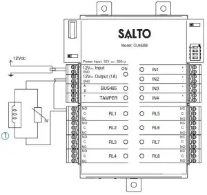
1 Electric Strike
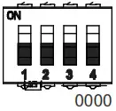
Offline configuration
- The unit must be connected to a CU4200 in stand-alone mode (dip-switch in the CU4200 -> 0000).
- In offline mode, the inputs are disabled.

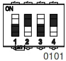
- The dip-switch configures the number of the output in the different relays as the following table.
- To assign the output number to a specific user see SALTO ProAccess SPACE User Manual.

TABLE 1
| RL1 | RL2 | RL3 | RL4 | RL5 | RL6 | RL7 | RL8 | RL1 | RL2 | RL3 | RL4 | RL5 | RL6 | RL7 | RL8 | RL1 | RL2 | RL3 | RL4 | RL5 | RL6 | RL7 | RL8 | |||
 | 1 | 2 | 3 | 4 | 5 | 6 | 7 | 8 | 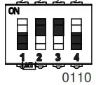 | 49 | 50 | 51 | 52 | 53 | 54 | 55 | 56 | 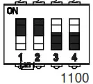 | 97 | 98 | 99 | 100 | 101 | 102 | 103 | 104 |
 | 9 | 10 | 11 | 12 | 13 | 14 | 15 | 16 | 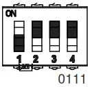 | 57 | 58 | 59 | 60 | 61 | 62 | 63 | 64 | 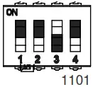 | 105 | 106 | 107 | 108 | 109 | 110 | 111 | 112 |
 | 17 | 18 | 19 | 20 | 21 | 22 | 23 | 24 | 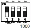 | 65 | 66 | 67 | 68 | 69 | 70 | 71 | 72 | 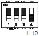 | 113 | 114 | 115 | 116 | 117 | 118 | 119 | 120 |
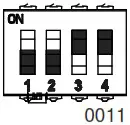 | 25 | 26 | 27 | 28 | 29 | 30 | 31 | 32 | 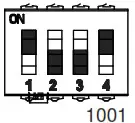 | 73 | 74 | 75 | 76 | 77 | 78 | 79 | 80 | 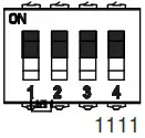 | 121 | 122 | 123 | 124 | 125 | 126 | 127 | 128 |
 | 33 | 34 | 35 | 36 | 37 | 38 | 39 | 40 | 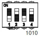 | 81 | 82 | 83 | 84 | 85 | 86 | 87 | 88 | |||||||||
 | 41 | 42 | 43 | 44 | 45 | 46 | 47 | 48 | 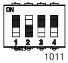 | 89 | 90 | 91 | 92 | 93 | 94 | 95 | 96 | |||||||||
Online Configuration:
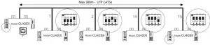
- Connect all the devices through the BUS485and power the CU4EB8.
- Create and set up the CU4EB8 on the Software (Consult the SALTO ProAccess SPACE user manual).
– Assign the CU4EB8 to the node it is connected to.
– Define the address in the BUS485.
– The relay out setup has to be done through the SALTO ProAccess SPACE software. - Put the Resistor in ONLINE mode.
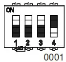
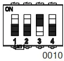
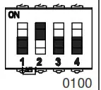
 – The CU4EB8 dip-switch setting is used to give each device on the BUS485 a unique address.
– Ensure that the address in the software is the same as the one you put on the hardware. (See Table 2).
– Both ends of the BUS485 must have the RS485BUS termination resistor in the ON position, intermediate devices need to have the resistor in the OFF position.
Supervised input connections
By default all inputs are disabled. They can be configured through the software. If the inputs are supervised, the resistance values R1 and R2 are defined in the software:1k (recommended), 1k5,2k2,3k3,4k7,6k8,10k.
 – The CU4EB8 dip-switch setting is used to give each device on the BUS485 a unique address.
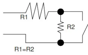
| ADDRESS | ADDRESS | ADDRESS | |||
| Address 1 | | Address 7 | | Address 13 |
| Address 2 | | Address 8 | | Address 14 |
| Address 3 | | Address 9 | | Address 15 |
| Address 4 | | Address 10 | ||
| Address 5 | | Address 11 | ||
| Address 6 | | Address 12 |
Set up example:
Same configuration at SALTOs ProAccess SPACE Software
Signaling:
The LEDs in the top layer of the CU4EB8 show the state of the system:
| LED name | Description |
| ON | GREEN ON: the unit is powered correctly |
| BLINKING RED: the unit is not powered properly (check power supply) | |
| OFF: not powered | |
| TAMPER | ON: tamper alarm active |
| OFF: tamper alarm not active | |
| IN1-IN4 | ON: active input (depends on the input type configured in the software) |
| OFF: inactive input (depends on the input type configured in the software) | |
| RL1-RL8 | ON: the relay is activated (NO is connected with C). |
| OFF: the relay is inactive (NC is connected with C). |
EN 50131-3:2009 & EN 60839-11-1:20013 Statements
Certification issued by ALTER TECHNOLOGY TÜV NORD S.A.U. for the models: CU4EB8T00 and CU4EB8G00. Stationary ACE, Type B.
Performance level:
– Security Grade 2 (EN 50131-3:2009), Class II
– Grade 2 (EN60839-11-1:2013), Class II
– IK04
– CU4EB8 contains 1x EEPROM (512Kbits)
– The unit shall be supplied by an EN 50131-6:2017 certified external power supply or by the power output of another SALTO Control Unit.


