
PCIe x16 2.0 Expansion Backplane (2019)
Model: OSS-PCIe-BP-2019
Installation Guide
SKU: OSS-PCIe-BP-2019
![]()
One Stop Systems
Preface
Advisories
Five types of advisories are used throughout this manual to provide helpful information, or to alert you to the potential for hardware damage or personal injury.
 NOTE
NOTE
Used to amplify or explain a comment related to procedural steps or text.
 IMPORTANT
Used to indicate an important piece of information or special “tip” to help you
 CAUTION
Used to indicate and prevent the following procedure or step from causing damage to the equipment.
 WARNING
Used to indicate and prevent the following step from causing injury.
 DANGER or STOP
Used to indicate and prevent the following step from causing serious injury or significant data loss
Disclaimer: We have attempted to identify most situations that may pose a danger, warning, or caution condition in this manual. However, the company does not claim to have covered all situations that might require the use of a Caution, Warning, or Danger indicator.
Safety Instructions
Always use caution when servicing any electrical component. Before handling the expansion chassis, read the following instructions and safety guidelines to prevent damage to the product and to ensure your own personal safety. Refer to the “Advisories” section for advisory conventions used in this manual, including the distinction between Danger, Warning, Caution, Important, and Note.
- Always use caution when handling/operating the computer. Only qualified, experienced, authorized electronics personnel should access the interior of the computer and expansion chassis per UL and IEC 60950-1
- The power supplies produce high voltages and energy hazards, which can cause bodily harm.
- Use extreme caution when installing or removing components. Refer to the installation instructions in this manual for precautions and procedures. If you have any questions, please contact Technical Support.
WARNING
Never modify or remove the radio frequency interference shielding from your workstation or expansion unit. To do so may cause your installation to produce emissions that could interfere with other electronic equipment in the area of your system.
When Working Inside a Computer
- Before taking covers off a computer, perform the following steps:
- Turn off the computer and any peripheral devices.
- Disconnect the computer and peripheral power cords from their AC outlets or inlets in order to prevent electric shock or system board damage.
In addition, take note of these safety guidelines when appropriate:
- To help avoid possible damage to systems boards, wait five seconds after turning off the computer before removing a component, removing a system board, or disconnecting a peripheral device from the computer.
- When you disconnect a cable, pull on its connector or on its strain-relief loop, not on the cable itself. Some cables have a connector with locking tabs. If you are disconnecting this type of cable, press in on the locking tabs before disconnecting the cable. As you pull connectors apart, keep them evenly aligned to avoid bending any connector pins. Also, before connecting a cable, make sure both connectors are correctly oriented and aligned.
CAUTION
Do not attempt to service the system yourself except as explained in this manual. Follow installation instructions closely.
Protecting Against Electrostatic Discharge
Electrostatic Discharge (ESD)
Warning Electrostatic Discharge (ESD) is the enemy of semiconductor devices. You should always take precautions to eliminate any electrostatic charge from your body and clothing before touching any semiconductor device or card by using an electrostatic wrist strap and/or rubber mat.
Static electricity can harm system boards. Perform service at an ESD workstation and follow proper ESD procedures to reduce the risk of damage to components. We strongly encourage you to follow proper ESD procedures, which can include wrist straps and smocks, when servicing equipment.
You can also take the following steps to prevent damage from electrostatic discharge (ESD):
- When unpacking a static-sensitive component from its shipping carton, do not remove the component’s anti-static packaging material until you are ready to install the component in a computer. Just before unwrapping the anti-static packaging, be sure you are at an ESD workstation or are grounded.
- When transporting a sensitive component, first place it in an anti-static container or packaging.
- Handle all sensitive components at an ESD workstation. If possible, use anti-static floor pads and workbench pads.
- Handle components and boards with care. Do not touch the components or contacts on a board. Hold a board by its edges or by its metal mounting bracket.
1 Introduction
PCI Express backplane with one PCIe x16 expansion slot with ATX power. Supports up to Gen3 cards.
1.1 Specifications
Item | Description |
| Form Factor | 2 PCIe x16 Slot |
| Dimensions | 2.25” x 4.5” |
| Power Consumption | Max power dissipation for board only (not counting power delivered to add-on cards) is 1.5 watts |
| Slot | One Target slot, x16 Gen 2 One End point slot, x16 Gen 2 |
| Operating Temperature | 0˚C to +85˚C environment |
| Operating Humidity | 10% to 90% relative humidity non-condensing |
| Storage Humidity | 5% to 95% relative humidity non-condensing |
| Industry Specifications |
|
| Agency Compliance |
|
| Operating System | Windows 10, Windows Server 2012 R2; Linux OS based |
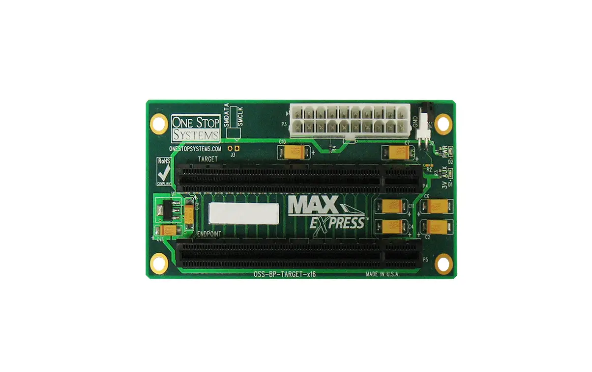
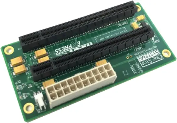
1.2 Overview
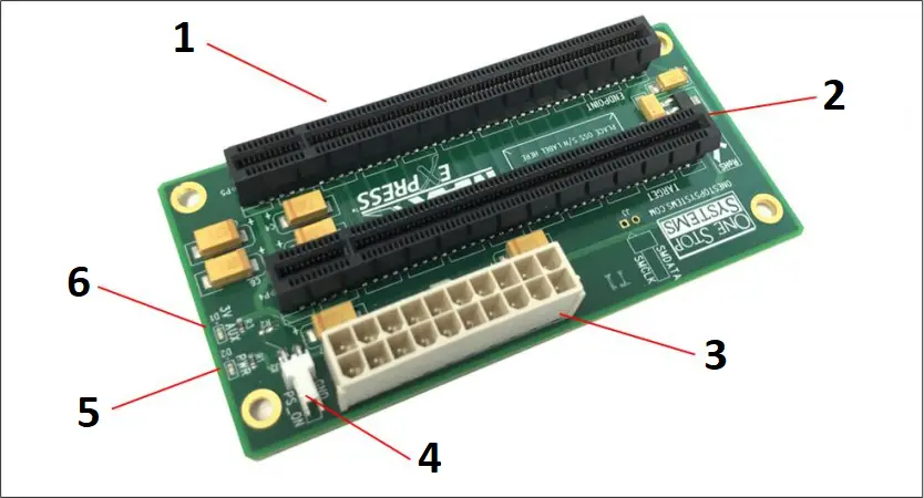
- End-point Slot / Downstream Slot (P3)
- Target Slot / Upstream Slot (P4)
- ATX Power Connector (P3)
- PS_ON (J2)
- PWR GOOD LED (D2)
- 3.3V Aux LED (D1)
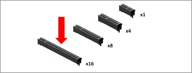
- End-point slot (P3): also known as downstream slot. This is the slot where an add-in or plug and play PCIe card is installed. It is a Gen2 x16 slot, accommodate x4, x8 and x16 PCie cards.
- Target slot (P4): Also known as Upstream slot. Designed for the Target card only. It is a Gen2 x 16 slot.
- PS_ON (J2): Enable force power ON. Forces the power supply to be ON all the time
- ATX Power Connector (P3): 20pin ATX Input Power
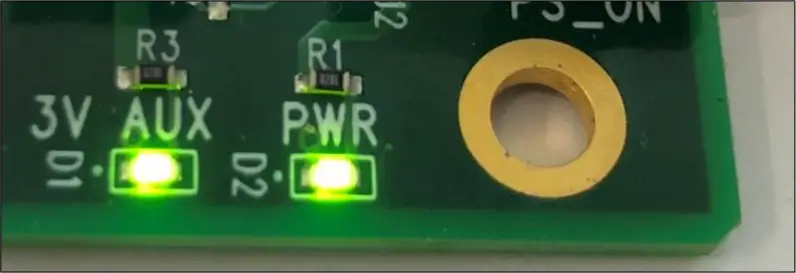
- PWR led (D2): Indicates power is present on the board
- 3.3V Aux led(D1): 3.3v aux is present on the board
Connector Pint-Outs
| Connector | Definition |
| J2 | Force Power ON |
| P3 | ATX Input Power (20 pin) |
| D2 | Power Good LED |
| D1 | 3.3v AUX Led |
| J1—Force Power ON | |
| PIN | Definition |
| 1 | PWR_ON# |
| 2 | GND |
| P3 – 20 PIN ATX Input Power | |||
Pin | Definition | Pin | Definition |
| 1 | +3.3V | 11 | +3.3V |
2 | +3.3V | 12 | -12V |
| 3 | GND | 13 | GND |
4 | +5V | 14 | PS_ON# |
| 5 | GND | 15 | GND |
6 | +5V | 16 | GND |
| 7 | GND | 17 | GND |
8 | PWRON | 18 | NC |
| 9 | +5VSB | 19 | +5V |
10 | +12V1 | 20 | +5V |
1.3 Block Diagram
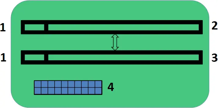
- x16 Gen 2
- End point Slot
- Target Slot
- 20 pin ATX Input Power
1.4 Dimensions
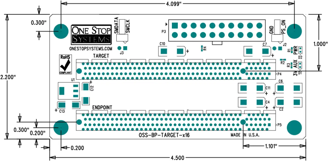
1.5 x16 Target Slot Connector Pin Outs
Pin # | Name | Pin # | Name | Mechanical Key |
| B1 | +12V | A1 | GND | |
B2 | +12V | A2 | +12V | |
| B3 | +12V | A3 | +12V | |
B4 | GND | A4 | GND | |
| B5 | SMCLK | A5 | NC | |
B6 | SMDAT | A6 | REFCLK1+ | |
| B7 | GND | A7 | REFCLK1- | |
B8 | +3.3V | A8 | NC | |
| B9 | PS_ON# | A9 | +3.3V | |
B10 | 3.3Vaux | A10 | +3.3V | |
| B11 | WAKE# | A11 | PERST# | |
B12 | RSVD | A12 | GND | End of the x1 Connector |
| B13 | GND | A13 | REFCLK2+ | |
B14 | PETp0 | A14 | REFCLK2- | |
| B15 | PETn0 | A15 | GND | |
B16 | GND | A16 | PERp0 | |
| B17 | PRSNT_X1# | A17 | PERn0 | |
B18 | GND | A18 | GND | |
| B19 | PETp1 | A19 | RSVD | End of the |
B20 | PETn1 | A20 | GND | |
| B21 | GND | A21 | PERp1 | |
B22 | GND | A22 | PERn1 | |
| B23 | PETp2 | A23 | GND | |
B24 | PETn2 | A24 | GND | |
| B25 | GND | A25 | PERp2 | |
B26 | GND | A26 | PERn2 | |
| B27 | PETp3 | A27 | GND | |
B28 | PETn3 | A28 | GND | |
| B29 | GND | A29 | PERp3 | |
B30 | RSVD | A30 | PERn3 | |
| B31 | PRSNT_X4# | A31 | GND | |
B32 | GND | A32 | RSVD | |
| B33 | PETp4 | A33 | RSVD | End of the |
B34 | PETn4 | A34 | GND | |
| B35 | GND | A35 | PERp4 | |
B36 | GND | A36 | PERn4 | |
| B37 | PETp5 | A37 | GND | |
B38 | PETn5 | A38 | GND | |
| B39 | GND | A39 | PERp5 | |
B40 | GND | A40 | PERn5 | |
| B41 | PETp6 | A41 | GND | |
B42 | PETn6 | A42 | GND | |
| B43 | GND | A43 | PERp6 | |
B44 | GND | A44 | PERn6 | |
| B45 | PETp7 | A45 | GND | |
B46 | PETn7 | A46 | GND | |
| B47 | GND | A47 | PERp7 | |
B48 | PRSNT_X8# | A48 | PERn7 | |
| B49 | GND | A49 | GND | |
B50 | PETp8 | A50 | RSVD | End of the x16 Connector |
| B51 | PETn8 | A51 | GND | |
B52 | GND | A52 | PERp8 | |
| B53 | GND | A53 | PERn8 | |
B54 | PETp9 | A54 | GND | |
| B55 | PETn9 | A55 | GND | |
B56 | GND | A56 | PERp9 | |
B57 | GND | A57 | PERn9 | |
| B58 | PETp10 | A58 | GND | |
B59 | PETn10 | A59 | GND | |
| B60 | GND | A60 | PERp10 | |
B61 | GND | A61 | PERn10 | |
| B62 | PETp11 | A62 | GND | |
B63 | PETn11 | A63 | GND | |
| B64 | GND | A64 | PERp11 | |
B65 | GND | A65 | PERn11 | |
| B66 | PETp12 | A66 | GND | |
B67 | PETn12 | A67 | GND | |
| B68 | GND | A68 | PERp12 | |
B69 | GND | A69 | PERn12 | |
| B70 | PETp13 | A70 | GND | |
B71 | PETn13 | A71 | GND | |
| B72 | GND | A72 | PERp13 | |
B73 | GND | A73 | PERn13 | |
| B74 | PETp14 | A74 | GND | |
B75 | PETn14 | A75 | GND | |
| B76 | GND | A76 | PERp14 | |
B77 | GND | A77 | PERn14 | |
| B78 | PETp15 | A78 | GND | |
B79 | PETn15 | A79 | GND | |
| B80 | GND | A80 | PERp15 | |
B81 | PRSNT_X16# | A81 | PERn15 | |
| B82 | RSVD | A82 | GND | |
1.6 x16 End Point Slot Connector Pin Outs
Pin # | Name | Pin # | Name | Mechanical Key |
| B1 | +12V | A1 | GND | |
B2 | +12V | A2 | +12V | |
| B3 | +12V | A3 | +12V | |
B4 | GND | A4 | GND | |
| B5 | SMCLK | A5 | NC | |
B6 | SMDAT | A6 | REFCLK2+ | |
| B7 | GND | A7 | REFCLK2- | |
B8 | +3.3V | A8 | NC | |
| B9 | NC | A9 | +3.3V | |
B10 | 3.3Vaux | A10 | +3.3V | |
| B11 | WAKE# | A11 | PERST# | |
B12 | RSVD | A12 | GND | End of the x1 Connector |
| B13 | GND | A13 | REFCLK1+ | |
B14 | PERp0 | A14 | REFCLK1- | |
| B15 | PERn0 | A15 | GND | |
B16 | GND | A16 | PETp0 | |
| B17 | PRSNT_X1# | A17 | PETn0 | |
B18 | GND | A18 | GND | |
| B19 | PERp1 | A19 | RSVD | End of the |
B20 | PERn1 | A20 | GND | |
| B21 | GND | A21 | PETp1 | |
B22 | GND | A22 | PETn1 | |
| B23 | PERp2 | A23 | GND | |
B24 | PERn2 | A24 | GND | |
| B25 | GND | A25 | PETp2 | |
B26 | GND | A26 | PETn2 | |
| B27 | PERp3 | A27 | GND | |
B28 | PERn3 | A28 | GND | |
| B29 | GND | A29 | PETp3 | |
B30 | RSVD | A30 | PETn3 | |
| B31 | PRSNT_X4# | A31 | GND | |
B32 | GND | A32 | RSVD | |
| B33 | PERp4 | A33 | RSVD | End of the |
B34 | PERn4 | A34 | GND | |
| B35 | GND | A35 | PETp4 | |
B36 | GND | A36 | PETn4 | |
| B37 | PERp5 | A37 | GND | |
B38 | PERn5 | A38 | GND | |
| B39 | GND | A39 | PETp5 | |
B40 | GND | A40 | PETn5 | |
| B41 | PERp6 | A41 | GND | |
B42 | PERn6 | A42 | GND | |
| B43 | GND | A43 | PETp6 | |
B44 | GND | A44 | PETn6 | |
| B45 | PERp7 | A45 | GND | |
B46 | PERn7 | A46 | GND | |
| B47 | GND | A47 | PETp7 | |
B48 | PRSNT_X8# | A48 | PETn7 | |
| B49 | GND | A49 | GND | |
B50 | PERp8 | A50 | RSVD | End of the x16 Connector |
| B51 | PERn8 | A51 | GND | |
B52 | GND | A52 | PETp8 | |
| B53 | GND | A53 | PETn8 | |
B54 | PERp9 | A54 | GND | |
| B55 | PERn9 | A55 | GND | |
B56 | GND | A56 | PETp9 | |
| B57 | GND | A57 | PETn9 | |
B58 | PERp10 | A58 | GND | |
| B59 | PERn10 | A59 | GND | |
B60 | GND | A60 | PETp10 | |
| B61 | GND | A61 | PETn10 | |
B62 | PERp11 | A62 | GND | |
| B63 | PERn11 | A63 | GND | |
B64 | GND | A64 | PETp11 | |
| B65 | GND | A65 | PETn11 | |
B66 | PERp12 | A66 | GND | |
| B67 | PERn12 | A67 | GND | |
B68 | GND | A68 | PETp12 | |
| B69 | GND | A69 | PETn12 | |
B70 | PERp13 | A70 | GND | |
| B71 | PERn13 | A71 | GND | |
B72 | GND | A72 | PETp13 | |
| B73 | GND | A73 | PETn13 | |
B74 | PERp14 | A74 | GND | |
| B75 | PERn14 | A75 | GND | |
B76 | GND | A76 | PETp14 | |
| B77 | GND | A77 | PETn14 | |
B78 | PERp15 | A78 | GND | |
| B79 | PERn15 | A79 | GND | |
B80 | GND | A80 | PETp15 | |
| B81 | PRSNT_X16# | A81 | PETn15 | |
B82 | RSVD | A82 | GND | |
NC = NOT CONNECTED
2 Hardware Requirements
The following steps will guide you through the installation of your HIB25-x8 Host and Target card.
2.1 Hardware & System Requirements
- Computer / Server motherboard with x16 Gen2 PCIe slot.
- Two Cable Adapter cards: OSS Host Card (x16 Gen 2) and OSS Target Card (x16 Gen2). NOTE: The HIB card works in pair (one as host card and other as target card)
- One x16 iPass cable
- Standard ATX Power Supply
2.1.1 PCIe Slot & Motherboard Requirement
Use a computer motherboard with a Gen2 x16 PCIe slot. .
2.1.2 Host and Target Cards
Use a x16 Gen2 Host and Target cards
- Target Card
- Host Card
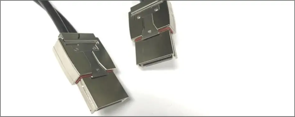
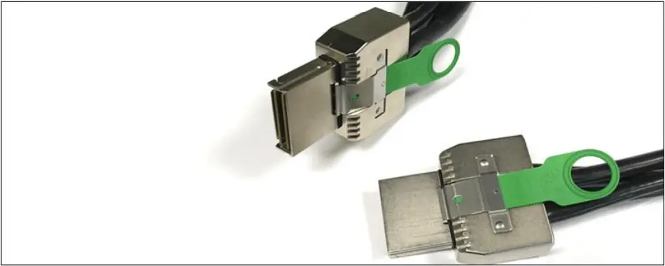
2.1.3 x16 iPass Cable
Use x16 iPass cable for connecting host card and target card
2.1.4 ATX Power Supply
You need an ATX standard power supply. You can use a power supply unit with a 24pin or 20pin power connector.
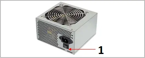
- ON/OFF Switch
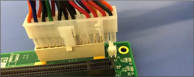
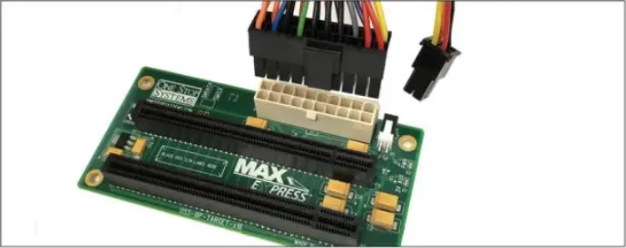
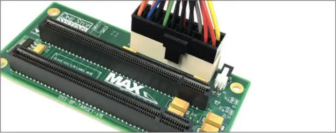
The INPUT power connector on the backplane has 20 pins. It will work with 24-pin ATX power connector, see photos below.
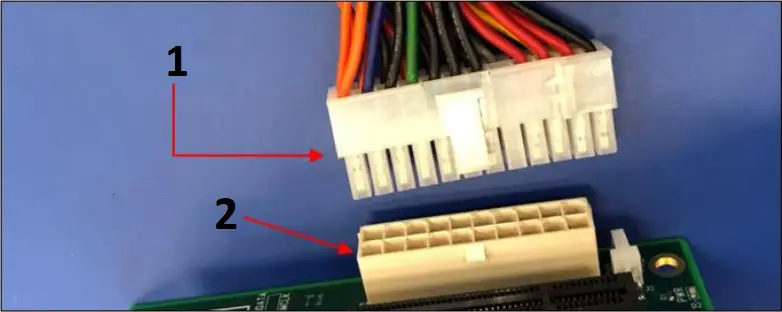
- 24-pin ATX power cable
- 20-pin input ATX power connector
2.2 Software Requirement
- Computer running Windows 7, 8, 10 and or Server
- No driver is needed for the Host card, Target card and backplane.
3 Installation Procedures
The ATX power cable must be connected first before installing the cable adapter card.
3.1 Connect ATX Power Supply
Place the “JUMPER” on the J2 header (PS_ON)
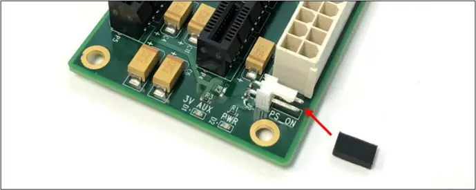
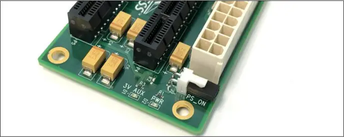
Plug-in the ATX power supply to the “ATX Input Power” connector on the board.
3.2 Select Host and Target Card
Select the appropriate card to use, makes sure you have the correct host and target cards. Below are photos to help you identify between Target and Host card.
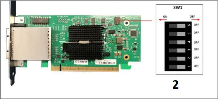
Host card: The card dipswitches are is set to operate in “Host Mode.
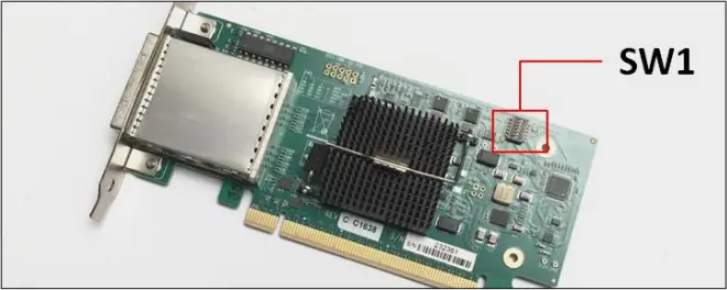
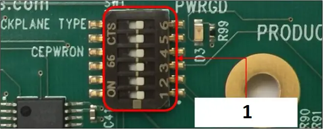
- Host Mode
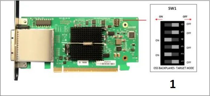
Target Card: The card dipswitches are set to operate in “Target Mode”
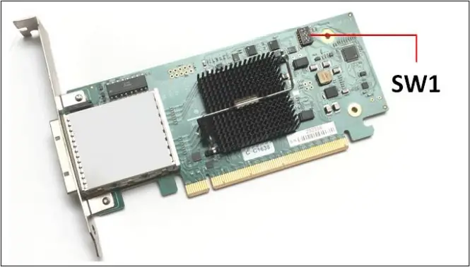
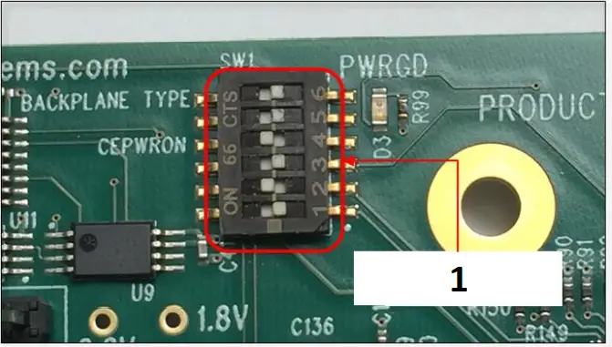
- Target Mode
3.3 Install Host card
Power down the host computer first before installing the host card. Do not install the host card while the computer is ON.
- Install the HIB25-X8 host card into the available PCIe slot in the computer motherboard. Use a x8 or x16 Gen2 PCIe slot.
- Secure the card
Install the host card in the computer. Plug in the host card in the x16 Gen2 PCIe slot. Secure the card.
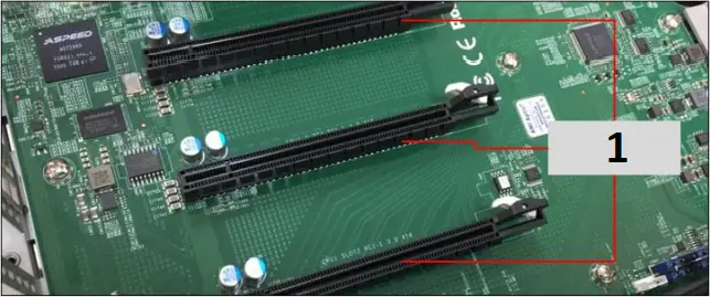
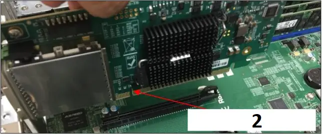
- x16 slot
- Host card (HIB38-x16)
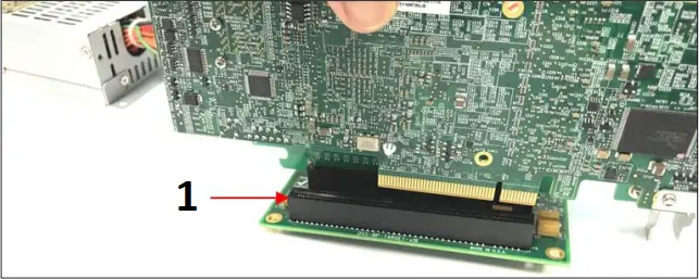
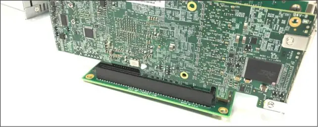
3.4 Install Target card
Do not plug in the target card while expansion unit or the expansion backplane is ON as this can damage the board. Turn OFF the unit first before installing the card.
The HIB Target card will only work in the OSS backplane designated “Upstream” slot. It will not function in the downstream slot or the end-point slot of the backplane.
Install the Target card in the OSS expansion backplane. Plug-in the target card in the designated Upstream slot of the backplane.
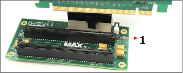
- Upstream Slot
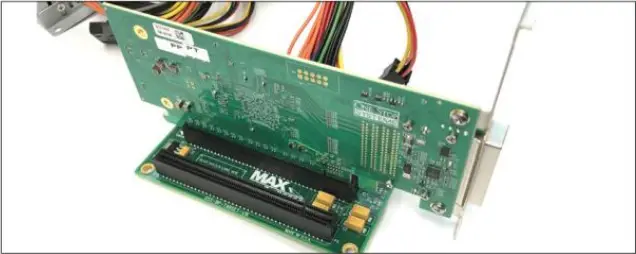
3.5 Install PCIe card
Plug-in your 3rd party PCIe card in the expansion backplane. Use the downstream slot of the OSS backplane. See photos below.
- Downstream Slot
3.6 Install link cable
- Connect the PCIe iPass x8 cable between the host and target cards. Plug in the cable to the host card.
- Plug in the other end of the cable to the target card. Make sure the cable is firmly latched in to the cable connectors of the card.
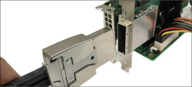
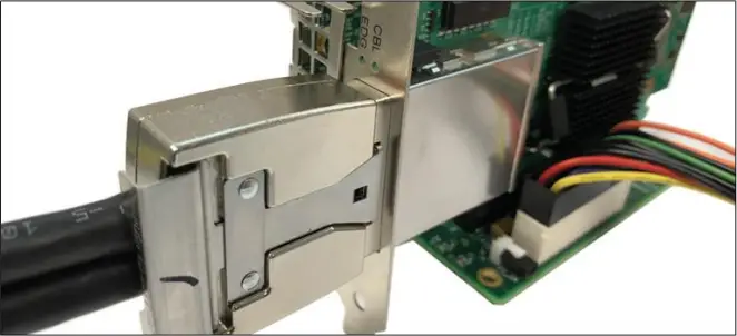
Photo below is a block diagram of an OSS expansion unit linked to a host server / computer.
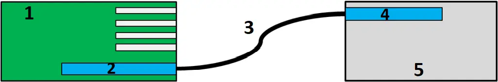
- OSS Backplane / Chassis
- OSS Target Card
- X16 iPass Cable
- OSS Host Card
- Host Server / Computer
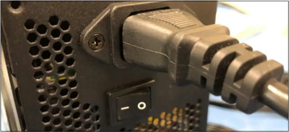
3.7 Turn ON Power Supply
Connect power to the PSU and turn the switch to ON position.
3.8 Power ON the Host system
- Turn On the main power of the host computer.
- Upon powering ON the Host system, it will send a sideband signal to the Target card triggering the target expansion system to turn ON.
If the expansion unit or the HIB card are not powering ON, check the link cable make sure it is firmly connected. The target and host card must be fully seated in the PCIe slot in order to work correctly.
4 Verify Hardware
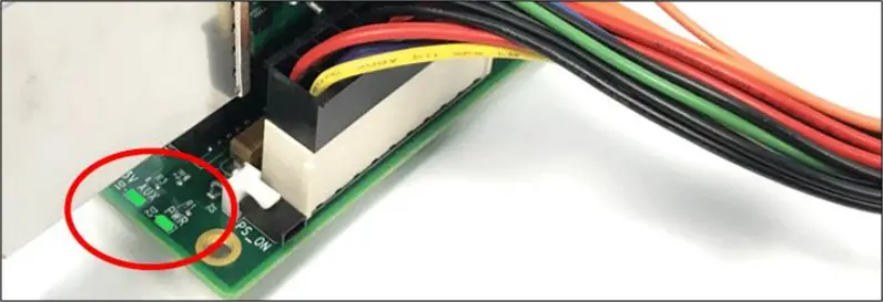
On the 1slot backplane, the following LEDs are illuminated.
- D1: 3V AUX LED
- D2: PWR LED
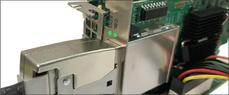
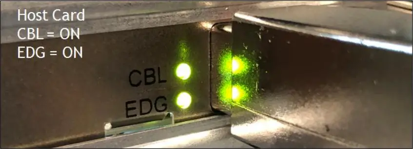
On the x16 host and target cards the following LEDs (located on the bracket) are illuminated.
- CBL
- EDG
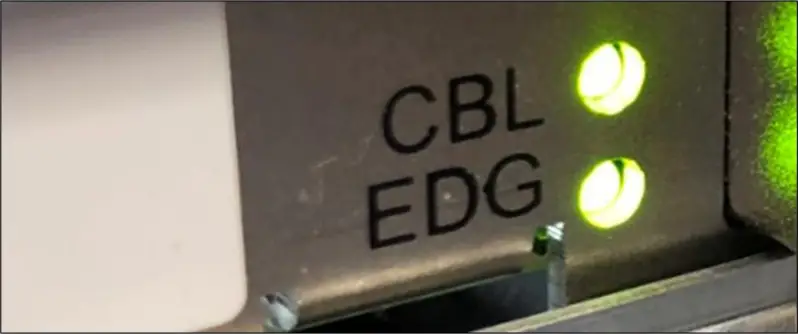
4.1 LED Definition
CBL – Signal detect on cable*
EDG – Signal detect on card edge*
*Signal detect does not mean it has a link, but rather it identifies there is a signal on the card edge. If the link does not appear to be stable, it could mean that there is a compliance pattern being generated by the PCIe device interfacing with this card.
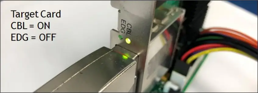
If the downstream PCIe slot on the backplane is not populated with a PCIe card, the EDG LED on the Target card will be OFF.
Only the CBL led is ON (as solid green). On the Host card, both CBL and EDG leds are ON. See photos below
5 Software Installation
No software or driver is required for the Host Adapter card.
6 How to Get More Help
You can visit the Technical Support FAQ pages on the Internet at https://www.onestopsystems.com/support
6.1 Contacting Technical Support
Our support department can be reached by phone at 1 (760) 745-9883. Support is available Monday through Friday, 8:00 AM to 5:00 PM PT. When contacting Technical Support make sure to include the following information:
- Exact and correct serial #
- Service Ticket or Case # (if you already submitted an online request)
- Computer Type & Model: Operating System
- Make & Model of PCI/PCIe cards: Application
- Problem description
When submitting an online technical support request always provide a valid working e-mail address, phone number, shipping address and proper contact name. Check your e-mail for an automated response containing the case # and updates. You can also visit our web site at: https://www.onestopsystems.com/support for a quick response, use the Technical Support and RMA Request Form available in the Support Section of the website. Simply complete the form with all required information. Please make sure that your problem description is sufficiently detailed to help us understand your problem.
Shipping or Transporting of Expansion Unit with PCI / PCIe cards
Any PCIe cards in should be removed (or not to be installed) prior to shipment to avoid or prevent possible damage. Note: Expansion board and PCIe / PCI cards that arrive damaged in shipment will not be covered under warranty.
6.2 Returning Merchandise
If factory service is required, a Service Representative will give you a Return Merchandise Authorization (RMA) number. Put this number and your return address on the shipping label when you return the item(s) for service. Please note that One Stop Systems WILL NOT accept COD packages, so be sure to return the product freight and duties-paid. Ship the well-packaged product to the address below:
Attention:RMA # ________, One Stop Systems
2235 Enterprise Street, #110
Escondido, CA 92029
USA
It is not required, though highly recommended, that you keep the packaging from the original shipment of your product. However, if you return a product for warranty repair/ replacement or take advantage of the 30-day money back guarantee, you will need to package the product in a manner similar to the manner in which it was received from our plant. We cannot be responsible for any physical damage to the product or component pieces of the product (such as the host or expansion interfaces for the expansion chassis) that are damaged due to inadequate packing. Physical damage sustained in such a situation will be repaired at the owner’s expense in accordance with Out of Warranty Procedures. Please, protect your investment, a bit more padding in a good box will go a long way to insuring the device is returned to use in the same condition you shipped it in. Please call for an RMA number first.
6.3 Online Support Resources
As a product user and customer, listed below are our Online Support Resources
https://www.onestopsystems.com/support provides Knowledgebase Articles such as troubleshooting methods, compatibility, FAQ, documentation, and product technical information.
If you need technical support, product assistance or have a technical inquiry we encourage you to submit it on-line using our Technical Support Form. If you need to send a unit for repair or diagnostic evaluation, fill out our RMA (Return Material Authorization) online request form.
![]()
2235 Enterprise Street, Suite#ll0, Escondido CA 92029
Toll-Free: +1(800)285-8900 US • Main: +l (760) 745-9883 • Fax: +l (760) 745-9824
OSS-PCIe-BP-2019


