![]() 2010-1 RB/SB Expansion Board
2010-1 RB/SB Expansion Board
Installation Guide
2010-1 RB/SB Expansion Board
Description
This document includes installation information for the following expansion boards:
- 2010-1-RB Expansion Board with four relay outputs
- 2010-1-SB Expansion Board with four supervised outputs
Relay expansion board
The relay expansion board has four voltage-free relay outputs each rated for 2 A at 30 VDC. Relays can be assigned to detection zones or programmed for activation based on system events.
Supervised expansion board
The supervised expansion board has four supervised outputs, each providing 24 VDC. The supervised outputs can be configured as sounder outputs, fire routing outputs, fire protection outputs, or fault warning outputs, and can be assigned to detection zones or programmed for activation based on system events.
When configured as sounder, fire routing, fire protection, or fault warning outputs, the control panel interface provides indications and the available control options.
When configured as a general purpose supervised output board, short and open circuit faults are indicated by the general Fault LED and the Expansion I/O Fault/Disabled LED on the control panel interface.
WARNING: To avoid personal injury or death from electrocution, disconnect the control panel from the mains power supply and batteries before installing this product.
To install the expansion board:
- Unplug the power supply unit, the batteries, and any other device cables connected to the control panel PCB.
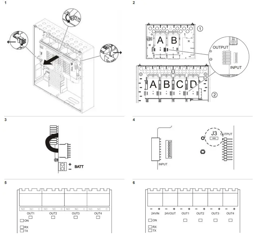
- Remove the holding screw and unclip and remove the control panel PCB, as shown in Figure 1 (for two- and four-zone control panels, unclip the PCB at each corner by pressing carefully on the holding studs).
- Install the expansion board into slot A on the left of the cabinet and push the board firmly into place. For two- and four-zone control panels refer to Figure 2, item 1. For 8-zone control panels, evacuation panels, and extinguishing panels refer to Figure 2, item 2.
To install more than one board, connect the INPUT and OUTPUT connectors of each board (as shown in Figure 2) before pushing the boards into the appropriate slots. - To install a supervised expansion board, configure the power source (if required). See “Configuration”.
- Replace the control panel PCB and reconnect all battery and power supply cables.
- Connect the expansion board in slot A to the control panel PCB, as shown in Figure 3.
Wiring
Relay expansion board
To wire the relay expansion board, connect all devices to OUT1, OUT2, OUT3, and OUT4 (NO, NC, and C). See Figure 5.
Supervised expansion board
To wire the supervised expansion board, connect all devices to OUT1, OUT2, OUT3, and OUT4. If required, connect the external power supply to 24VIN and 24VOUT. See Figure 6.
Caution: Never use the auxiliary output to power expansion boards connected to the same control panel as this might damage the control panel hardware.
For Class B output installation:
All outputs require a 15 kΩ end-of-line resistor for termination.
If an output is not used, the 15 kΩ end-of-line resistor must be installed across the unused output terminals.
For Class A output installation:
All groups of outputs (OUT1/2, OUT3/4) require a 4.7 kΩ, 1%, 1/4 W end-of-line resistor for termination. If an output group is not used, the 4.7 kΩ, 1%, 1/4 W end-of- line resistor must be installed across the unused output group terminals.
For additional Class A wiring requirements, refer to your control panel installation manual.
Observe polarity for all connections.
Configuration
Power source configuration
If power requirements exceed the maximum current the control panel can provide, connect an external 24 VDC power supply and remove jumper J3 (Figure 4).
| Jumper J3 | Power source |
| ON (default) | 24 VDC is supplied by the control panel |
| OFF | 24 VDC is supplied by an external powwer supply |
Expansion board functionality
The expansion board functionality and event programming is configured at the control panel interface. See your control panel installation manual for further information.
Maintenance
Basic maintenance consists of a yearly inspection. Do not modify the internal wiring or circuitry of the board.
Expansion board fault indications
Additional fault diagnostics are indicated by the ON and OUT1, OUT2, OUT3, and OUT4 LEDs on the expansion board, as shown below.
| Fault | Indication | Action |
| Communication | The board ON LED flashes quickly | Check that all board connections are secure. Check the board configuration at the control panel. |
| Power supply | The board ON LED and all board OUT LEDs flash slowly | Check that the power supply of the board is > 21 V. Check that jumper J3 is correctly configured for the power source in use. |
| Output | The board OUT LED flashes slowly | Locate and fix the fault on the corresponding output. Reset the control panel if required (see note). |
| Board failure | The board ON LED and all board OUT LEDs flash quickly | Replace the board. |
Note: For the supervised expansion board all faults must be reset manually by pressing the Reset button on the control panel interface. Open and short circuit faults in Class B wiring are reset automatically when the output is deactivated.
Specifications
| Operating voltage | 24 VDC |
| Relay contact rating | 2A at 30 VDC |
| Operating temperature | −5 to +40ºC |
| Storage temperature | −5 to +70ºC |
| Relative humidity | 10 to 95% noncondensing |
| Dimensions | 127 × 76 mm |
| Number of boards that can be installed Two- and four-zone control panels Eight-zone control panels Evacuation panels Extinguishing panels | 2 max. 4 max. 4 max. 4 max. |
| Weight 2010-1-RB 2010-1-SB | 46g 48g |
| Control panel current consumption [1] Two- and four-zone control panels Eight-zone control panels Evacuation control panels Extinguishing control panels | Maximum current 160 mA 300 mA 300 mA 300 mA |
| 2010-1-RB current consumption perboard Standby Activated | 15 mA max. 45 mA max. |
| 2010-1-SB current consumption per board Standby Activated | 15 mA max. 1 A max. [2] 300 mA max. (at 40ºC) [3] |
| 2010-1-SB current consumption per output Standby Activated | 2 mA max. 250 mA max.(at 25ºC) |
| Output voltage for the 2010-1 SB Standby Activated Nominal output voltage Maximum output voltage Minimum output voltage | -15 VDC +24 VDC +28 VDC +21 VDC |
- Maximum current provided by the panel for all installed boards.
- With power supplied by an external 24 VDC power supply.
- With power supplied by the control panel.
Regulatory information
| Conformity | |
| Manufacturer | Carrier Manufacturing Poland Spółka Z o.o., Ul. Kolejowa 24, 39-100 Ropczyce, Poland. Authorized EU manufacturing representative: Carrier Fire & Security B.V., Kelvinstraat 7, 6003 DH Weert, Netherlands. |
Contact information
For contact information or to download the latest product documentation, visit firesecurityproducts.com.


