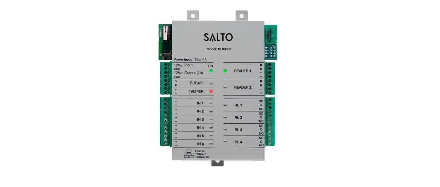
SALTO CU42E0 Electronic Door Controller
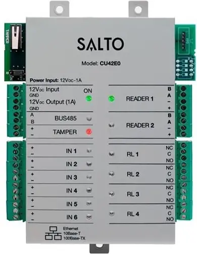
The door controller reads the encrypted data contained on the carrier and allows for updating of the carrier via SALTO Virtual Network technology, making it possible to cancel lost or stolen cards remotely.
It is equipped with input connections that permit third party readers integration.
Mechanical Installation
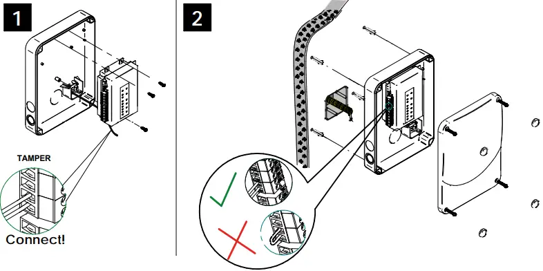 Note: Follow the same connection model, using the CU tamper input, when using a third party electric box equipped with a tamper opening detection.
Installation guide XS4 Controller
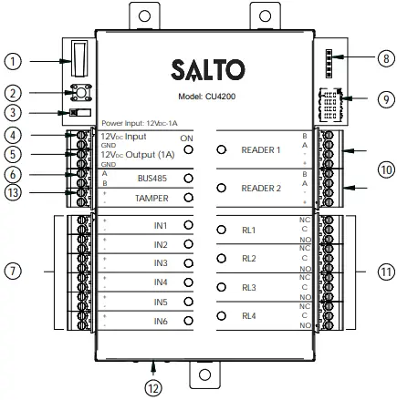
- Physical tamper switch to be operated by external electric box models.
- Clear button must be pushed (not more than 5 seconds) if the configuration has been changed, (i.e. reader added, connected by Ethernet, device connected by BUS485) and the tamper alarm must be activated by removing the tamper switch connector.
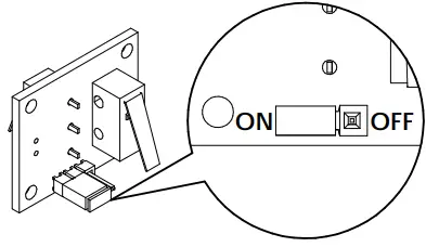
- BUS RS485 Terminal resistor must be in the ON position when the CU is connected at the end of the BUS.
- Power input.
- Power output: this output is directly connected to the power input port protected by a 1A fuse.
- BUS485.
- Inputs: installer must identify the bridge cable needed depending on the input configuration.
- PPD Connection.
- Address configure (Only CU4200) All connected CU addresses must be different from each other.
- Connection to readers: check reader installation manual to see recommended cable, connections and max. distances.
- Relay connections: please take into account the max. load restrictions (2A-30VDC). Use the provided varistor if an inductive load is used.
- Ethernet connection (only CU42E0).
- Tamper input to connect the tamper signal from the SALTO electric box or other compatible devices.
Factory configuration IN1 DOOR state for DOOR1 unsupervised NC IN2 RTE input for DOOR1 unsupervised NO IN3 DOOR state for DOOR2 unsupervised NC IN4 RTE input for DOOR2 unsupervised NO IN5 Office input for DOOR1 unsupervised NO IN6 Office input for DOOR2 unsupervised NO RL1 Lock Relay for DOOR1 RL2 Tamper Alarm, DLO and intrusion DOOR 1 RL3 Lock Relay for DOOR2 RL4 Tamper Alarm, DLO and intrusion DOOR 2
Input connections
(Input supervision has not been evaluated by UL) CUADAP or third partie readers
| Wiegand | Omron | RS232 | |
| IN3 | D0 output | Clock output | |
| IN4 | D1 output | Data output | TX output |
| IN5 | D0 output | Clock output | |
| IN6 | D1 output | Data output | TX output |
Supervised input connections
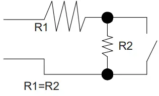
The resistance value R1 and R2 are defined in the software: 1k (recommended), 1k5, 2k2, 3k3, 4k7 6k8, 10k
Electrical characteristics
Operation conditions
| Min | Typ | Max | Unit | |
| Temperature | 0 | 25 | 60 | ºC |
| Humidity | 35 | 85 | ||
Power
| Min | Nom. | Max | Unit |
| InputVoltage | 12 | V | |
| Current consumption | 2Note1 | A | |
| Outputport currentNote2 | 1 | A | |
| Reader Output Voltage | 12 | V |
Input
| Electrical characteristics | 5v Note 3 | |
| Configuration | ViaSoftware | Note4 |
Cable recommendation
| EthernetNote5 | UTP CAT5e |
| BUS485 | Twisted pair |
| Inputs | AWG24 |
| Readers | AWG18 |
Output relays
Ratedload(resistive) 2A‐30Vdc
- Note 1: This is consumption of the CU with 2 WR and using the output power port. The CU alone consumes 400mA. Depending on the installation installer must calculate the Power Supply needed.
- Note 2: Same voltage as the input.
Note 3: 1K pull‐up resistor. - Note 4: See the software User Manual.
- Note 5: When Ethernet is available
Installation example
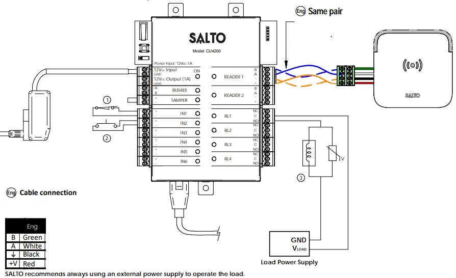
- NC Switch DOOR
- NO Switch RTE
- Electric Strike
Installation example with RJ45
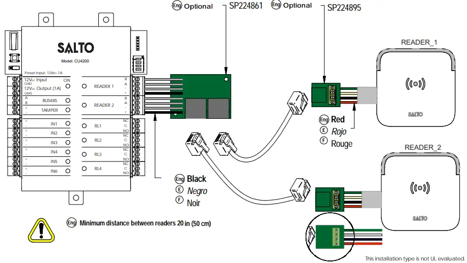
Minimum distance between readers 20 in (50 cm)
Configuration
- Prepare all the network connections (including Ethernet cable) setting up the dip-switch of each CU4200. Generate a tamper alarm by opening the CU housing or removing the tamper switch cable and then press the CLR button to detect all the connected readers. Check that the readers LEDs are ON (READER 1, READER 2).
- Perform the set up in the software (Consult SALTO ProAccess SPACE user guide). Set up all the CU4200s with their dip-switches and assign the IP address to the CU42E0.
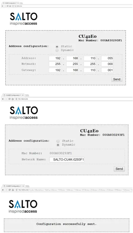
- Adress the CU42E0:
- Press the CLR BUTTON (CU42E0) to detect the readers and the connected CU4200. Check that the reader’s LEDs blink and the BUS485 LEDs are switched ON.
- The CU42E0 is a DHCP ready device. If there’s no DCHP server, the user can manually set up a static IP address using a web browser.
- Press the CLR button for 5 seconds to access the addressing mode (LED ON will blink orange).
- Access the IP address 192.168.0.234 with your web browser. Set up the network parameters and click on “send”. 3.2.3. The CU42E0 will leave the addressing mode automatically, but you can also leave the addressing mode manually by pressing the CLR button for 5 seconds.
- Use SALTO ProAccess software to detect the device (consult SALTO ProAccess Software user manual).

Dipswitch set up
When CU4200 is used offline, the dip-switch setting has to be OFF for all 4 switches (0000).
When connected to an online CU42E0 by BUS485, the CU4200 dip-switch setting is used to give each device on the BUS485 a unique address. Ensure that the address in the software is the same as the one you put on the hardware. (See Table). Both ends of the BUS485 must have the RS485 BUS termination resistor in the ON position, intermediate CU4200s need to have the resistor in OFF position.
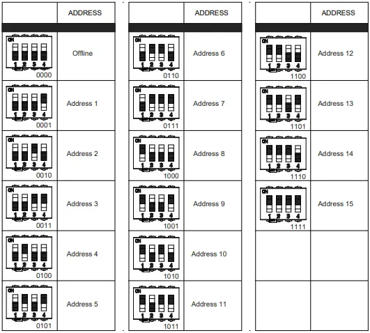
Set up example:
Same configuration at SALTOs ProAccess SPACE Software
Max 300m ‐ UTP CAT5e
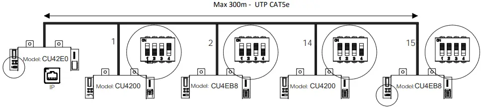
(The interconnection has not been evaluated by UL, the model CU4EB8 has not been evaluated by UL)
Maximum number of devices on BUS485: 16 units, with a maximum of 4 units CU4200 and 15 units CU4EB8.
Signaling
The LEDs in the top layer of the CU show the state of the system:
| LED name | Description |
| ON | GREEN ON: the unit is powered correctly |
| BLINKING RED: the unit is not powered properly (check power supply) | |
| BLINKING ORANGE: addressing mode | |
| OFF: not powered | |
| BUS485 | ON CU4200:The unit is communicating with the CU42E0 ON CU42E0: To be defined |
| OFF CU4200:The unit is not communicating with the CU42E0 (press the CLR to start detection process) OFF CU42E0: To be defined | |
| TAMPER | ON: tamper alarm active |
| OFF: tamper alarm not active | |
| IN1-IN6 | ON: active input (depends on the input type configured in the software) |
| OFF: inactive input (depends on the input type configured in the software) | |
| READER | ON: the reader is communicating with the CU |
| OFF: the reader is not communicating with the CU (press the CLR to start detection process) | |
| RL1-RL4 | ON: the relay is activated (NO is connected with C). |
| OFF: the relay is inactive (NC is connected with C). |
All contents current at time of publication.
SALTO Systems S.L. reserves the right to change availability of any item in this catalog, its design, construction, and/or materials.


