![]()
Evco S.p.A. · Codice 104K802E04
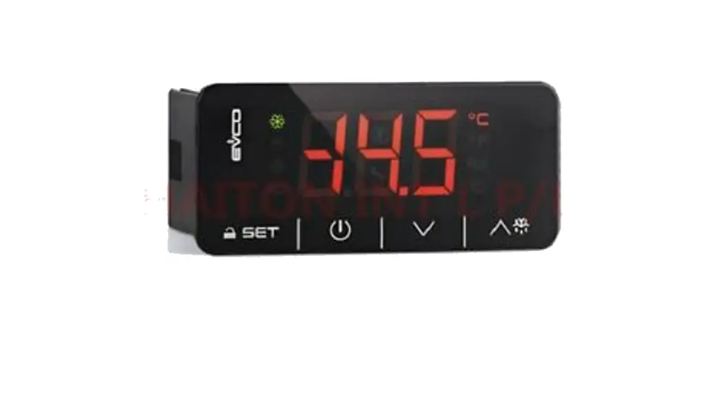
EVK802 Digital controller for quick coolers management
version 1.04
PREPARATION
Important
Please read these instructions carefully prior to installation and use, and follow all the precautions for installation and electrical connections; keep these instructions with the device for future consultation.
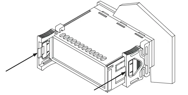
Installation
Per panel, using the snap-on brackets supplied; the dimensions are given in mm.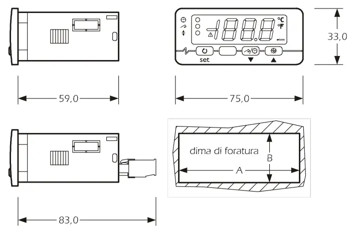
| DIMENS. | MINIMUM | TYPICAL | MAXIMUM |
| A | 71,0 | 71,0 | 71,8 |
| B | 29,0 | 29,0 | 29,8 |
Recommendations for installation:
- the maximum depth with screw terminal blocks is 59.0
- the maximum depth with removable terminal blocks is 83.0
- the panel thickness must not exceed 8,0 mm
- ensure that the operating conditions (operating temperature, humidity, etc.) are within the limits indicated in the technical data sheets
- do not install the device near any sources of heat (heating elements, hot air conduits, etc.), equipment containing powerful magnets (large diffusers, etc.), areas affected by direct sunlight, rain, humidity, excessive dust, mechanical vibration, or shock
- in compliance with safety regulations, the device must be installed correctly, and in such a way as to protect against any contact with electrical parts; all safety devices must be fixed so that they cannot be removed without the use of tools.
Electrical connections
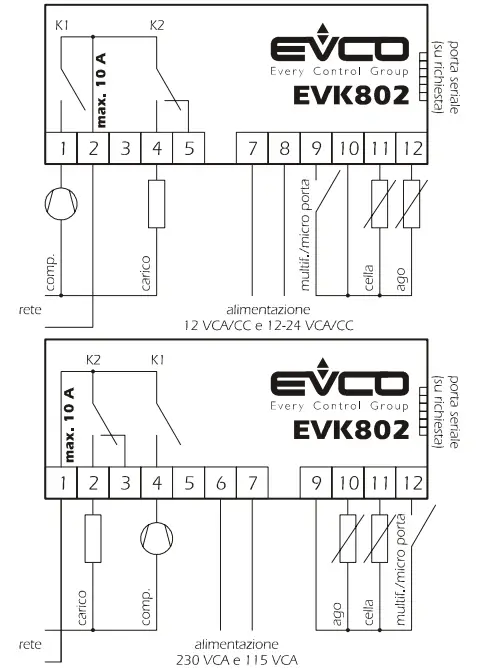
With reference to the electrical circuit diagram:
- the service controlled by relay K2 depends on parameter u0
- the serial port (available on request) is the port used for communicating with the monitoring system (by means of a serial interface, via TTL, using the MODBUS communication protocol) or with the programming key; the port must not be used for both purposes simultaneously.
Points to note for connecting to the electricity supply
- do not use electric or pneumatic screw-wrenches on the terminal board
- if the device has been moved from a cold to a warm environment, condensation may have formed inside; please wait for approx. one hour prior to switching on
- ensure that the voltage, frequency, and operational power of the device are compatible with the local power supply
- disconnect the power prior to proceeding with any kind of maintenance operation
- do not use the device as a safety device
- for repairs and any information relating to the device, contact the Evco dealer network.
USER INTERFACE
Introductory information
The device has the following operational states:
- “on” (the device is switched on and an operating cycle is running)
- “stand-by” (the device is switched on but no operating cycle is running)
- “off” (the device is not switched on).
If power is interrupted during a timed blast chilling operation, when power is restored, chilling will continue from the time point at which the interruption occurred (with a maximum error of 10 minutes).
If power is interrupted during a set-temperature blast chilling operation, when power is restored, chilling will start again from the beginning.
If power is interrupted during a storage operation when power is restored the storage operation will be reset.
If power is interrupted while in “stand-by” mode when power is restored the device will be in the same state.
The display
In the “on” state, during normal operation, the display shows:
- the amount of time remaining for a timed blast chilling operation, if this is ongoing
- the temperature measured by the pin probe if a set-temperature chilling operation is ongoing
- the temperature of the cabinet, if storage is ongoing.
In “standby” mode, during normal operation, the display shows the temperature of the cabinet for ½ s every 3 s.
Defrosting and the evaporator fan
The service controlled by relay K2 depends on parameter u0:
- if u0 = 0, the service controlled by relay K2 will be defrosting (electrical defrosting; the evaporator fan is not controlled)
- if u0 = 1, the service controlled by relay K2 will be the evaporator fan (defrost stopping the compressor):
– during blast chilling, the operation of the evaporator fan depends on parameter F0
– during storage, the operation of the evaporator fan depends on the parameter F2
– the evaporator fan is started during defrosting.
In “standby” mode it is only possible to activate manual defrosting; if the service controlled by relay K2 is the evaporator fan (parameter u0 = 1), during defrosting the evaporator fan will be switched on, and during drip-draining, this will be switched off.
To start defrosting in manual mode:
- ensure no procedure is running
- press
 for 4 s.
Defrosting is never activated during blast-chilling.
Defrosting occurs periodically during storage; it is possible to start defrosting manually.
Viewing the status of the compressor and the evaporator fan
To view the compressor status:
- ensure no procedure is running
- press: the display will show the first available label:
– if the display shows “C-1”, the compressor will be switched on
– if the display shows “C-0”, the compressor will be switched off
– if the display shows “C-P”, compressor protection will be ongoing (parameters C0, C1, C2, and i7).
To view the status of the evaporator fan: - ensure no procedure is running
- press twice: the display will show the first available label:
– if the display shows “F-1”, the evaporator fan will be switched on
– if the display shows “F-0”, the evaporator fan will be switched off
– if the display shows “F-P”, then evaporator fan deferred activation will be ongoing (parameter F8).
To exit the procedure: - Press until the display shows the ongoing status value (see paragraph 2.2), or leave for 15 s.
If the service controlled by relay K2 is defrosting (parameter u0 = 0), labels “F-1”, “F-0” and “F-P” will not be displayed.
Buzzer mute
- ensure no procedure is running
- press any key (the first keypress does not trigger the associated effect).
OPERATIONAL CYCLES
Introductory information
The device has the following operational cycles:
- timed positive chilling and storage
- timed negative chilling and storage
- set-temperature positive chilling and storage
- set-temperature negative chilling and storage.
Set-temperature cycles are preceded by a test step in order to check the correct insertion of the pin probe (see paragraph 3.6).
To re-start using the same settings as the last cycle run: - ensure that the device is in “stand-by” mode, that no procedures are running and that another cycle has not been selected
- press
 2 s: the display will show the label of the last cycle run
 - press within 60 s: in the case of a timed cycle, the display will show the duration of the blast chilling step (in minutes), or in the case of a set-temperature cycle, the set target temperature
- press or
 within 15 s to change the value (the setting re- mains active until another cycle is selected, when the value r1, r2, r3, or r4 is restored)
 - press within 15 s: the cycle will be activated.
- press within 60 s: in the case of a timed cycle, the display will
show the duration of the blast chilling step (in minutes) or in the case of a set-temperature cycle, the set target temperature - press or within 15 s to change the value (the setting remains active until another cycle is selected when the value rl, r2, r3, or r4 is restored)
- press within 15 s: the cycle will be activated.
Timed positive blast chilling and storage cycle
To start the cycle
• ensure the device is in “stand-by” mode and no procedures are running
• press ![]() to select “PoS” and ensure the LED
to select “PoS” and ensure the LED![]() is flashing
is flashing
• press![]() within 15 s: the display will show the duration of the blast chilling step (in minutes)
within 15 s: the display will show the duration of the blast chilling step (in minutes)
• press ![]() or within 15 s to change the value (the setting re- mains active until another cycle is selected, when the value assigned by parameter r1 is restored)
or within 15 s to change the value (the setting re- mains active until another cycle is selected, when the value assigned by parameter r1 is restored)
• press![]() : the display will show the chilling operational setpoint (in °C/°F) and the LED
: the display will show the chilling operational setpoint (in °C/°F) and the LED![]() will flash
will flash
• press ![]() or
or![]() within 15 s to change the value (the setting re- mains active until another cycle is selected, when the value assigned by parameter r7 is restored)
within 15 s to change the value (the setting re- mains active until another cycle is selected, when the value assigned by parameter r7 is restored)
• press![]() within 15 s: the cycle will be activated.
within 15 s: the cycle will be activated.
Also, look at parameters RB and E0.
During chilling:
- the display shows the residual chilling time remaining
- the LED
 is on
is on - parameter r1 sets the chilling time duration
- parameter r7 sets the operational setpoint
- Press several times to:
– display the message “PoS”
– display the cabinet temperature
– exit the procedure, or leave for 15 s.
Once the chilling period has elapsed:
- the device switches to storage mode
- the display shows the message “End”
- the buzzer sounds for the period of time set by parameter AA
- press any key to mute the buzzer; press once more to cancel the message “End”.
During storage:
- the display shows the cabinet temperature
- the LEDs and
 are on
 - the parameter r9 sets the operational setpoint
- Press several times to:
– display the message “PoS”
– exit the procedure, or leave for 15 s.
To interrupt the cycle:
- press for 2 s.
Timed negative chilling and storage cycle
To start the cycle:
- ensure the device is in “stand-by” mode and no procedures are running
- Press to select “nEg” and ensure the LED is flashing
- press within 15 s: the display will show the duration of the blast chilling step (in minutes)
- press or within 15 s to change the value (the setting re- mains active until another cycle is selected, when the value assigned by parameter r2 is restored)
- press: the display will show the chilling operational setpoint (in °C/°F) and the LED will flash
- press or within 15 s to change the value (the setting re- mains active until another cycle is selected, when the value assigned by parameter r8 is restored)
- press within 15 s: the cycle will be activated.
Also, look at parameters RB and E0.
During chilling:
- the display shows the residual chilling time remaining
- the LED is on
- parameter r2 sets the chilling time duration
- parameter r8 sets the operational setpoint
- pressseveral times to:
– display the message “nEg”
– display the cabinet temperature
– exit the procedure, or leave for 15 s.
Once the chilling period has elapsed:
- the device switches to storage mode
- the display shows the message “End”
- the buzzer sounds for the period of time set by parameter AA
- press any key to mute the buzzer; press once more to cancel the message “End”.
During storage:
- the display shows the cabinet temperature
- the LEDs are on
- the parameter RA sets the operational setpoint
- Press several times to:
– display the message “nEg”
– exit the procedure, or leave for 15 s.
To interrupt the cycle:
- press for 2 s.
Set-temperature positive blast chilling and storage cycle
To start the cycle:
- ensure the device is in “stand-by” mode and no procedures are running
• press ![]() to select “PoS” and ensure the LED
to select “PoS” and ensure the LED![]() is flashing
is flashing
• press ![]() within 15 s: the display will show the blast chilling endpoint temperature
within 15 s: the display will show the blast chilling endpoint temperature
• press ![]() or
or![]() within 15 s to change the value (the setting re- mains active until another cycle is selected, when the value assigned by parameter r3 is reset)
within 15 s to change the value (the setting re- mains active until another cycle is selected, when the value assigned by parameter r3 is reset)
• press![]() : the display will show the chilling operational setpoint (in °C/°F) and the LED
: the display will show the chilling operational setpoint (in °C/°F) and the LED![]() will flash
will flash
• press ![]() or
or![]() within 15 s to change the value (the setting re- mains active until another cycle is selected, when the value assigned by parameter r7 is restored)
within 15 s to change the value (the setting re- mains active until another cycle is selected, when the value assigned by parameter r7 is restored)
• press ![]() within 15 s: the cycle will be activated.
within 15 s: the cycle will be activated.
Also, look at parameters RB and E0.
Prior to starting the cycle:
- the test is run in order to check correct pin probe insertion (see paragraph 3.6):
– if the outcome of the test is positive, the cycle will be started
– if the outcome of the test is negative, the cycle will be started in timed mode.
During chilling:
- the display shows the temperature measured by the pin probe
- the LED
 is on
is on - the parameter r3 sets the blast chilling endpoint temperature
- the parameter r5 sets the maximum chilling time duration
- the parameter r7 sets the operational setpoint
- Press several times to:
– display the maximum residual chilling time remaining
– display the message “PoS”
– display the flashing cabinet temperature
– exit the procedure, or leave for 15 s.
If the temperature measured by the pin probe reaches the chilling endpoint temperature prior to the expiry of the maximum chilling time duration:
- the device will switch to storage mode
- the display will show the message “End”
- the buzzer will sound for the period of time set by parameter AA
- press any key to mute the buzzer; press once more to cancel the message “End”.
If the temperature measured by the pin probe does not reach the chilling endpoint temperature prior to the expiry of the maximum chilling time duration:
- chilling will continue
- the LED will flash and the LED
 will be on
 - the buzzer will sound
- Press several times to:
– mute the buzzer
– display the time elapsed since the maximum chilling time expired
– display the cabinet temperature
– display the message “PoS”
– exit the procedure, or leave for 15 s - when the temperature measured by the pin probe reaches the chilling endpoint temperature:
– the device switches to storage mode
– the LED will continue to flash and the LED will stay on
– the display will show the message “End”
– the buzzer will sound for the period of time set by parameter AA
– press any key to mute the buzzer; press once more to cancel the message “End”.
During storage:
- the display shows the cabinet temperature
- if chilling had a positive outcome, the LEDs and will be on; if chilling had a negative outcome, the LEDs and will be on and the LED will flash
- the parameter r9 sets the operational setpoint
- Press several times to:
– display the message “PoS”
– exit the procedure, or leave for 15 s.
To interrupt the cycle:
- pressfor2 s.
Set-temperature negative chilling and storage cycle
To start the cycle:
- ensure the device is in “stand-by” mode and no procedures are running
- Press to select “nEg” and ensure the LED is flashing
- press within 15 s: the display will show the blast chilling endpoint temperature
- press or within 15 s to change the value (the setting re- mains active until another cycle is selected, when the value assigned by parameter r4 is restored)
- press: the display will show the chilling operational setpoint (in °C/°F) and the LED will flash
- press or within 15 s to change the value (the setting remains active until another cycle is selected when the value assigned by parameter r8 is restored)
- press within 15 s: the cycle will be activated.
Also, look at parameters RB and E0.
Prior to starting the cycle:
- the test is run in order to check correct pin probe insertion (see paragraph 3.6):
-if the outcome of the test is positive, the cycle will be started
– if the outcome of the test is negative, the cycle will be started in timed mode
During chilling:
- the display shows the temperature measured by the pin probe
- the LED is on
- the parameter r4 sets the chilling endpoint temperature
- the parameter r6 sets the maximum chilling time duration
- the parameter r8 sets the operational setpoint
- pressseveral times to:
– display the maximum residual chilling time remaining
– display the message “nEg”
– flashing display the cabinet temperature
– exit the procedure, or leave for 15 s.
If the temperature measured by the pin probe reaches the chilling endpoint temperature prior to the expiry of the maximum chilling time duration:
- the device will switch to storage mode
- the display will show the message “End”
- the buzzer will sound for the period of time set by parameter AA
- press any key to mute the buzzer; press once more to cancel the message “End”.
If the temperature measured by the pin probe does not reach the chilling endpoint temperature prior to the expiry of the maximum chilling time duration:
- chilling will continue
- the LED will flash and the LED will be on
- the buzzer will sound
- Press several times to:
– mute the buzzer
– display the time elapsed since the maximum chilling time expired
– display the cabinet temperature
– display the message “nEg”
– exit the procedure, or leave for 15 s - when the temperature measured by the pin probe reaches the chilling endpoint temperature:
– the device will switch to storage mode
– the LEDwill continue to flash and the LED will continue to stay on
– the display will show the message “End”
– the buzzer will sound for the period of time set by parameter AA
– press any key to mute the buzzer; press once more to cancel the message “End”.
During storage:
• the display shows the cabinet temperature
• if chilling had a positive outcome, the LEDs ![]() and
and ![]() will be on; if chilling had a negative outcome, the LEDs
will be on; if chilling had a negative outcome, the LEDs![]() and
and ![]() will be on and the LED
will be on and the LED![]() will flash
will flash
• the parameter RA sets the operational setpoint
• press![]() several times to:
several times to:
– display the message “nEg”
– exit the procedure, or leave for 15 s.
To interrupt the cycle:
- pressfor2 s.
Test to check correct pin probe insertion
Set-temperature cycles are preceded by a test step in order to check correct pin probe insertion.
The test has two stages:
- if the outcome of the first stage is positive, the second will not be run
- if the outcome of the first stage is negative, the second will be run.
The outcome of the first stage is positive if “the temperature measured by the pin probe – the temperature of the cabinet” is greater than the value set by parameter RC at least 3 times out of 5 (the comparison is made every 10 s); if parameter RC is set to 0, neither the first nor second stages will be run.
The outcome of the second stage is positive if the difference “temperature measured by the pin probe – temperature of the cabinet” is greater by at least 1ºC/1ºF (with respect to the previous comparison) at least 6 times out of 8 (the comparison is made every “rd/8 s”).
If the outcome of the test is positive:
- the cycle will be activated.
the cycle will be activated:
- the cycle will be started in timed mode
- the LED will flash.
If power is interrupted during the test, when power is restored, the test will start again from the beginning.
SETTINGS
The temporary setting of operational setpoint during storage
• ensure the device is in “stand-by” mode and no procedures are running
• press![]() : the LED
: the LED ![]() will flash
will flash
• press ![]() or
or![]() within15 s
within15 s
• press![]() or leave for 15 s.
or leave for 15 s.
The setting remains active until another operational cycle is selected when the value assigned by parameter r9 or ra is restored.
Setting the configuration parameters
The parameters are arranged on two levels.
To access the first level:
- ensure the device is in “stand-by” mode and no procedures are running
- press and for 4 s: the display will show “PA”
To access the second level:
- access the first level
- Press or select “PA”
- press
- press or within 15 s to set “-19”
- press or leave for 15 s
- press and for4 s: the display will show “CA1”.
To select a parameter:
- press or
To modify a parameter:
- press
- press or within 15 s
- press or leave for 15 s.
To exit the procedure:
- press and for 4 s, or leave for 60 s.
I interrupt the device power supply after altering the parameters.
Resetting configuration parameter default values
- ensure the device is in “stand-by” mode and no procedures are running
pressand for 4 s: the display will show “PA” - press
- press or within 15 s to set “743”
- press or leave for 15 s
- press and per 4 s: the display will show “dEF”
- press
- press or within 15 s to set “149”
- press or leave for 15 s: the display will flash “dEF” for 4 s, after which the device will exit the procedure
- interrupt the power to the device.
Ensure that the parameter default values are appropriate, particularly if the probes are NTC type.
SIGNALS
Signals
| LED | MESSAGE |
timed chilling LED
| |
set-temperature chilling LED
| |
storage LED
| |
| alarm LED if on, an alarm is ongoing degree Celsius LED if on, the unit of measurement for temperature in degrees Celsius (parameter P2) |
ºF | degree Fahrenheit LED if on, the unit of measurement for temperature is degrees Fahrenheit (parameter P2) |
decimal point | minute LED if flashing, the unit of measurement of magnitude displayed is the minute |
CODE | MESSAGE |
– d – | defrosting or drip draining is ongoing |
ALARMS
Alarms
| CODE | MESSAGE |
| AL | Minimum temperature alarm Remedies: • check the cabinet temperature • check parameters A1 and A2Consequences: • the device will continue to function normally |
| AH | Maximum temperature alarm Remedies: • check the cabinet temperature • check parameters A3 and A4Consequences: • the device will continue to function normally |
| id | Micro-port input alarm (only in “stand-by” mode and if parameter i0 is set to 0 or 1) Remedies: • check the causes which activated the input • check parameters i0 and i1Consequences: • the outcome set by parameter i0 |
| iA | Compressor protection input alarm (only if parameter i0 is set to 2) Remedies: • check the causes which activated the input • check parameters i0 and i1Consequences: • the compressor will be shut down |
When the cause that triggered the alarm has been resolved, the device restores normal operation.
INTERNAL DIAGNOSTICS
Internal diagnostics
| CODE | MESSAGE |
| Pr1 | Cabinet probe error Remedies: • see P0 parameter • check probe integrity • check the probe-device connection • check the cabinet temperatureConsequences if the error occurs while in “stand-by” mode: • if parameter C11 is set to 0, it will not be possible to start any of the cycles • if parameter C11 is set to 1, the pin probe will function as the cabinet probe, and only timed cycles will be allowed to start Consequences if the error occurs during a timed chilling operation: Consequences if the error occurs during a set-temperature chilling operation: • if parameter C11 is set to 0, the cycle will be interrupted |
| Pr2 | Pin probe error Remedies: • the same as for the previous case, but in relation to the pin probeConsequences if the error occurs while in “stand-by” mode: • only timed operation cycles will be allowed to start Consequences if the error occurs during a timed chilling operation: Consequences if the error occurs during a set-temperature chilling operation: Consequences if the error occurs during storage mode: |
TECHNICAL DATA
Technical data
Case: grey self-extinguishing.
Front panel protection classification (use copper conductors only): IP 65.
Connections: Screw terminal blocks (power supply, inputs, and outputs), 6 pin connector (serial port; available on request); extractable terminal block (power supply, inputs, and outputs) available on request.
Operating temperature: from 0 to 55 °C ( I 0 90% relative humidity, without condensation).
Power supply: 230 VAC, 50/60 Hz, 3 VA (nominal); 115 VAC or 12-24 VAC/DC or 12 VAC/DC by request.
Insulation class: 2.
Alarm buzzer: integrated.
Sensor Inputs: 2 (cabinet probe and pin probe) for PTC/NTC probes.
Digital Inputs: I (door switch/multifunction) for NA/NC contact (clean contact, 5 V I mA).
Sensor range: from -50.0 to 150.0 °C for PTC probes, from -40.0 to 105.0 °C for NTC probes.
Sensitivity: 0. I °C/1°C/1°F.
Digital outputs: 2 relays:
- compressor relay: 16 A res. @250 VAC, 5 FLA, 30 LRA (NA contact) versions with 12 VAC/DC and 12-24 VAC/DC; 8 A res. @ 250 VAC, 2 FLA, 12 LRA otherwise
- defrosting/evaporator fan relay: 8 A res.
@250 VAC, 2 FLA, 12 LRA (exchange contacts).
The maximum permitted current on loads is 10 A.
Serial port: port for communicating with the monitoring system (by means of a serial interface, via TTL, using the MODBUS communication protocol) or with the programming key; available on request.
CONFIGURATION PARAMETERS
First level configuration parameters
| PARAM | MIN. | MAX. | M.U. | DEF. | MAIN CONTROLLER |
| r0 | 0,1 | 15,0 | °C/°F (I) | 2,0 | parameter r7, r8, r9, and Ra differential |
| rl | 1 | 600 | min | 90 | timed positive blast chilling duration |
| r2 | 1 | 600 | min | 240 | timed negative blast chilling duration |
| r3 | -99,0 | 99,0 | °C/°F (I) | 3,0 | positive blast chill end-point temperature (temperature detected by the pin probe) |
| r4 | -99,0 | 99,0 | °C/°F (I) | -18,0 | negative blast chill end-point temperature (temperature detected by the pin probe) |
| r5 | 1 | 600 | min | 90 | set-temperature positive blast chilling maximum duration |
| r6 | 1 | 600 | min | 240 | set-temperature negative blast chilling maximum duration |
| r7 | -99,0 | 99,0 | °C/°F II) | 0,0 | positive blast chilling operational setpoint (cabinet temperature) |
| r8 | -99,0 | 99,0 | °C/°F (I) | -40,0 | negative blast chilling operational setpoint (cabinet temperature) |
| r9 | -99,0 | 99,0 | °C/°F (I) | 2,0 | postpositive blast chill storage operational setpoint (cabinet temperature) |
| rA | -99,0 | 99,0 | °C/°F (I) | -20,0 | post negative blast chill storage operational setpoint (cabinet temperature) |
Second level configuration parameters
| PARAM | MIN. | MAX. | M.U. | DEF. | SENSOR INPUTS |
| CAI | -25,0 | 25,0 | °C/°F (1) | 0,0 | cabinet probe offset |
| CA2 | -25,0 | 25,0 | °C/°F (1) | 0,0 | pin probe offset |
| PO | 0 | I | – – – | 0 | probe type 0 = FTC |
| P1 | 0 | I | – – – | I | degree Celsius decimal point (for the quantity displayed during normal operation) I = YES |
| P2 | 0 | I | – – – | 0 | unit of temperature measurement (2) 0 = °C I = °F |
| P3 | 0 | I | – – – | I | pin probe enabling I = YES |
| PARAM | MIN. | MAX. | M.U. | DEF. | MAIN CONTROLLER |
| r0 | 0,1 | 15,0 | °C/°F (I) | 2,0 | parameter r7, r8, r9, and Ra differential |
| rl | 1 | 600 | min | 90 | timed positive blast chilling duration |
| r2 | 1 | 600 | min | 240 | timed negative blast chilling duration |
| r3 | -99,0 | 99,0 | °C/°F (I) | 3,0 | positive blast chill end-point temperature (temperature detected by the pin probe) |
| r4 | -99,0 | 99,0 | °C/°F (I) | -18,0 | negative blast chill end-point temperature (temperature detected by the pin probe) |
| r5 | 1 | 600 | min | 90 | set-temperature positive blast chilling maximum duration |
| r6 | 1 | 600 | min | 240 | set-temperature negative blast chilling maximum duration |
| r7 | -99,0 | 99,0 | °C/°F (I) | 0,0 | positive blast chilling operational setpoint (cabinet temperature) |
| r8 | -99,0 | 99,0 | °C/°F ( I ) | -40,0 | negative blast chilling operational setpoint (cabinet temperature) |
| r9 | -99,0 | 99,0 | °C/°F ( I ) | 2,0 | postpositive blast chill storage operational setpoint (cabinet temperature) |
| rA | -99,0 | 99,0 | °C/°F ( I ) | -20,0 | post negative blast chill storage operational setpoint (cabinet temperature) |
| rb | 0 | 2 | – – – | I | kind of cycle enabled 0 = positive chilling |
| rc | 0,0 | 99,0 | °C/°F (I) | 5,0 | “temperature detected by the pin probe – temperature of the cabinet” difference for the first stage of the test to check correct pin probe insertion (see paragraph 3.6) 0 = test will not be performed (neither the first nor second stages) |
| rd | 1 | 99 | s | 60 | duration of the second stage of the test to check correct pin probe insertion (see paragraph 3.6J |
| PARAM. | MIN. | MAX. | M.U. | DEF | COMPRESSOR PROTECTION |
| C0 | 0 | 240 | min | 0 | operational cycle deferred compressor start-up; deferred compressor power restoration also following a power interruption during an operational cycle |
| C 1 | 0 | 240 | min | 5 | minimum elapsed time period between two consecutive compressor start-up operations |
| C2 | 0 | 240 | min | 3 | minimum compressor shut-down time |
| C3 | 0 | 240 | s | 0 | minimum compressor start-up time |
| C4 | 0 | 240 | min | I 0 | storage cabinet probe error compressor shut-down duration; see also C5 and C6 (only if CII = 0) |
| C5 | 0 | 240 | min | I 0 | positive storage cabinet probe error compressor start-up duration; see also C4 (only if CIT = 0) |
| C6 | 0 | 240 | min | 20 | negative storage cabinet probe error compressor start-up duration; see also C4 (only if CII = 0) |
| C I 1 | 0 | I | — | 0 | pin probe operation during cabinet probe error 0 = pin probe IF THE ERROR OCCURS DURING A TIMED OR SET TEMPERATURE BLAST CHILLING OPERATION – the cycle will be interrupted IF THE ERROR OCCURS DURING A STORAGE OPERATION – compressor activity will depend on parameters C4, C5 and C6 I = both pin probe and cabinet probe IF THE ERROR OCCURS DURING TIMED BLAST CHILLING – the pin probe will operate as a cabinet probe and chilling will continue IF THE ERROR OCCURS DURING SET-TEMPERATURE BLAST CHILLING – the pin probe will operate as both a pin probe and a cabinet probe and chilling will continue’ it is recommended to set the 10 parameters to 2 (COMPRESSOR PROTECTION) IF THE ERROR OCCURS DURING A STORAGE OPERATION – the pin probe will operate as a cabinet probe and storage will continue |
| PARAM. | MIN. | MAX. | M.U. | DEF | DEFROST |
| d0 | 0 | 99 | h | 8 | defrost interval (3) 0 = regular periodic defrosting will never be enabled |
| d3 | 0 | 99 | min | 30 | defrost duration 0 = defrosting will never be enabled |
| d7 | 0 | 15 | min | 2 | drip-drain duration |
| pARAM | MIN. | MAX. | M.U. | DEF. | TEMPERATURE ALARMS (4) |
| Al | 0,0 | 99.0 | °C/°F (1) | 10.0 | the temperature below which the minimum temperature alarm is activated: see also A2 (5) |
| A2 | 0 | 1 | — | 1 | minimum temperature alarm type 0 = no alarm 1 = depending on parameters r9 and rA (or ‘r9 – AI’ and “rA – An |
| A4 | 0.0 | 99.0 | °C/°F (1) | 10,0 | the temperature above which the maximum temperature alarm is activated: see also AS (5) |
| AS | 0 | 1 | — | 1 | maximum temperature alarm type 0 = no alarm I = depending on parameters r9 and rA (or 1–9 + A4′ and “rA + M”) |
| A6 | 0 | 240 | min | 15 | storage operation start-up temperature alarm delay |
| A7 | 0 | 240 | min | 15 | temperature alarm delay |
| A8 | 0 | 240 | min | 15 | drip-drain end maximum temperature alarm delay 16) |
| A9 | 0 | 240 | min | 1 5 | door switch input deactivation maximum temperature alarm delay (only if i0 = 0 or 1) (7) |
| AA | 0 | 240 | s | 5 | blast chill completion buzzer duration |
| PARAM | MIN. | MAX. | M.U. | DEE. | EVAPORATOR FAN (only if u0 = I) |
| FO | 0 | 2 | — | 2 | evaporator fan activity during chilling 0 = off |
| F2 | 0 | 2 | — | 1 | evaporator fan activity during storage 0 = off |
| F8 | 0 | 99 | min | 0 | evaporator fan start-up delay following defrost cycle start |
| PARAM | MIN. | MAX. | M.U. | DEE | DIGITAL INPUTS |
| i0 | 0 | 4 | — | 1 | digital input operation 0 = DOOR SWITCH – in this case parameters I 1, i2, and i3 assume significance: enabling input will cause the evaporator fan to be shut down (at most for the period of time set by i3 or until input will be disabled) 181 (91 1 = DOOR SWITCH INPUT – in this case, parameters I 1, i2, and i3 assume significance: enabling input will cause the compressor and evaporator fan to be shut down (at most for the period of time set by i3 or until input will be disabled) (8) (9) 2 = COMPRESSOR PROTECTION – in this case, parameters I 1 and i7 assume significance: the compressor will be shut-down, the display will flash code 1A” and the buzzer will be activated (until the input will be deactivated) 3 = DOOR SWITCH INPUT – in this case, parameters I 1, i2, and i3 assume significance: enabling input will cause the evaporator fan to be shut down (at most for the period of time set by i3 or until input will be disabled) (8) 4 = 2aQIILISOICLUNELEC – in this case, parameters I 1, i2, and i3 assume significance: enabling input will cause the compressor and evaporator fan to be shut down (at most for the period of time set by i3 or until input will be disabled) 181 (10) |
| i1 | 0 | 2 | — | 2 | digital input contact type 0 = NA (input active with contact closed) |
| i2 | -1 | 120 | min | 30 | door switch input alarm activation delay (solo se i0 = 0 o I) -1= the alarm will not sound |
| i3 | -1 | 120 | min | 15 | door switch input activation effect maximum duration (only if i0 = 0 or I) -1= the effect will last until the input will be disabled |
| i7 | 0 | 120 | min | 0 | compressor protection deactivation compressor delay (only if i0 = 2) |
| PARAM | MIN. | MAX. | M.U. | DEF. | DIGITAL OUTPUTS |
| u0 | 0 | 1 | — | 1 | service controlled by relay K2 (see paragraph 2.3) 0 = defrosting |
| PARAM | MIN. | MAX. | M.U. | DEF. | SERIAL NETWORK (MODBUS) |
| LA | 1 | 247 | — | 247 | device address |
| Lb | 0 | 3 | — | 2 | baud rate 0 = 2.400 baud |
| LP | 0 | 2 | — | 2 | parity 0 = none (no parity) |
| PARAM | MIN. | MAX. | M.U. | DEE. | ENABLING |
| E0 | 0 | 3 | — | 1 | quantity modifiable quickly before starting the cycle 0 = no quantity 2 = if you have selected a timed chilling cycle, the chilling duration, and the chilling operational setpoint 3 = if you have selected a timed chilling cycle, the chilling duration, and the chilling operational setpoint |
| E9 | 0 | 1 | — | 1 | reserved |
- the unit of measurement depends on parameter P2
- set the parameters relating to the controllers appropriately after altering parameter P2
- the device stores the defrost interval count every 30 minutes; altering parameter d0 has the effect of concluding the previous defrost interval or
manual defrost activation - the temperature alarm functions are only enabled during storage operations
- the parameter differential is 2.0 ºC/4 ºF
- there are no temperature alarms during defrosting and drip draining, if they occur following defrost activation
- there is no maximum temperature alarm while door switch input is enabled if occurring after input activation
- the evaporator fan will be shut down providing defrosting is not ongoing
- the compressor and/or ventilator fan are shut down 10 s after input activation
- the compressor is shut down 10 s after input activation.
 The device must be disposed of in accordance with local regulations pertaining to the collection of electrical and electronic appliances.
![]()
EVCO S.p.A.
Via Mezzaterra 6, 32036 Sedico Belluno ITALY
Phone +39-0437-852468
Fax +39-0437-83648
[email protected]
www.evco.it
This document belongs to Evco; unless you are authorized by Evco, you can not publish it.
Evco does not take any responsibility for features, technical data, and possible mistakes related to this document or coming by its use.
Evco does not take any responsibility for damages coming from the non-observance of the additional information.
Evco reserves the right to make any change without prior notice and at any time without prejudice to the basic safety and operating features.


