
![]()
EV3143
Controller with two independent regulators for refrigerated milk storage units and ice cream batch freezers

- 230 VAC or 115 VAC power supply (according to the model)
- 2 analogue inputs (PTC/NTC)
- door switch/multi-purpose input
- main relay 16 A res. @ 250 VAC
- alarm buzzer
- TTL MODBUS slave port for BMS
- hot or cold mode regulation.
MEASUREMENTS AND INSTALLATION
Measurements in mm (inches). To be fitted to a panel, snap-in brackets provided.
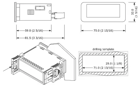
INSTALLATION PRECAUTIONS
- the thickness of the panel must be between 0.8 and 2.0 mm (1/32 and 1/16 in)
- ensure that the working conditions are within the limits stated in the TECHNICAL SPECIFICATIONS section
- do not install the device close to heat sources, equipment with a strong magnetic field, in places subject to direct sunlight, rain, damp, excessive dust, mechanical vibrations, or shocks
- in compliance with safety regulations, the device must be installed properly to ensure adequate protection from contact with electrical parts. All protective parts must be fixed in such a way as to need the aid of a tool to remove them.
ELECTRICAL CONNECTION
| N.B. • use cables of an adequate section for the current running through them • to reduce any electromagnetic interference, locate the power cables as far away as possible from the signal cables. |
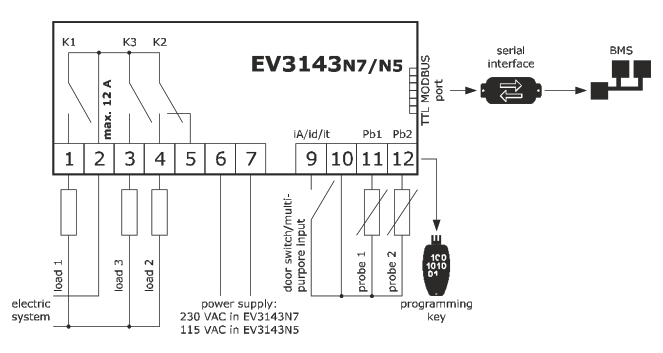
| P10 | OPERATION | PROBE 1 | PROBE 2 | LOAD 1 | LOAD 2 | LOAD 3 |
| 0 | controller with two independent regulators | regulator 1 | regulator 2 | regulator 1 | regulator 2 | alarm |
| 1 | controller for refrigerated milk storage units | tank | auxiliary | compres- sor | auxiliary | beater |
| 2 | controller for ice cream batch freezers | tank | plate | compres- sor | plate heaters | beater |
PRECAUTIONS FOR ELECTRICAL CONNECTION
- if using an electrical or pneumatic screwdriver, adjust the tightening torque
- if the device is moved from a cold to a warm place, humidity may cause condensation to form inside. Wait for about an hour before switching on the power
- make sure that the supply voltage, electrical frequency, and power are within the set limits. See the section TECHNICAL SPECIFICATIONS
- disconnect the power supply before carrying out any type of maintenance
- do not use the device as a safety device
- for repairs and for further information, contact the EVCO sales network.
FIRST-TIME USE
- Carry out the installation following the instructions given in the section MEASUREMENTS AND INSTALLATION.
- Power up the device as set out in the section ELECTRICAL CONNECTION: an internal test will startup.
The test normally takes a few seconds; when it is finished the display will switch off. - Configure the device as shown in the section Setting configuration parameters.
PAR. DEF. PARAMETER MIN… MAX. SP1 0.0 load 1 setpoint r1… r2 SP2 0.0 load 2 setpoint r12… r13 SP3 0.0 beater setpoint r16… r17 PO 1 type of probe 0 = PTC 1 = NTC P2 0 temperature measurement unit 0 = °C 1 = °F P10 0 operating logic 0 = controller with two independent regulators
1 = controller for refrigerated milk storage units
2 = controller for ice cream batch freezers 1…Then check that the remaining settings are appropriate; see the section CONFIGURATION PARAMETERS.
- Disconnect the device from the mains.
- Make the electrical connection as shown in the section ELECTRICAL CONNECTION, without powering up the device.
- When connecting to an RS-485 network, connect the EVIF22TSX interface; see the relevant instruction sheets.
- Power up the device again.
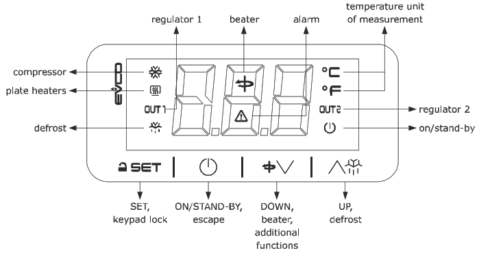
USER INTERFACE AND MAIN FUNCTIONS
Switching the device on/off
 If POF = 1 (default), touch the ON/STAND-BY key for 4 s.
If the device is switched on, the display will show the P5 value (“probe 1 temperature” default); if the display shows an alarm code, see the section ALARMS.
| LED | ON | OFF | FLASHING |
| compressor on | compressor off | – compressor protection in progress – setpoint being set | |
| plate heaters on | plate heaters off | setpoint being set | |
| regulator 1 on | regulator 1 off | – load 1 protection in progress – setpoint being set | |
| defrost active | – | – | |
| beater on | beater off | setpoint being set | |
| alarm active and silenced – | – | alarm active and not silenced | |
| temperature displayed | – | – | |
| regulator 2 on | regulator 2 off | – load 2 protection in progress – setpoint being set | |
| device off | device on | device being switched on/off |
When 30 s have elapsed without the keys being pressed, the display will show the “Loc” label and the keypad will automatically lock.
Unlocking the keypad
Touch a key for 1 s: the display will show the label “UnL”.
Quick setting:
- of setpoints (if P9 = 1 or 3)
- beater switch on/off times (if P9 = 2 or 3)
Check that the keypad is not locked.
| 1. | Touch the SET key: the display will show the label “SP1”. | |
| 2. | Touch the UP or DOWN key within 15 s to set the load 1 setpoint value within the limits r1 and r2 (default “-50… 50”). | |
| 3. | Touch the SET key: the display will show the label “SP2”. | |
| 4. | Touch the UP or DOWN key within 15 s to set the load 2 setpoint value within the limits r12 and r13 (default “-50… 50”). | |
| 5. | Touch the SET key: the display will show the label “SP3”. | |
| 6. | Touch the UP or DOWN key within 15 s to set the beater setpoint value within the limits r16 and r17 (default “-50… 50”). | |
| 7. | Touch the SET key: the display will show the label “t0”. | |
| 8. | Touch the UP or DOWN key within 15 s to set the time the beater is switched off within the limits 0… 240 min. | |
| 9. | Touch the SET key: the display will show the label “t1”. | |
| 10. | Touch the UP or DOWN key within 15 s to set the time the beater is switched on within the limits 0… 240 min. | |
| 11. | Touch the SET key (or take no action for 15 s). |
Settings are temporary: when the device is switched back on (and after a power failure), it resets the values SP1, SP2, SP3, t0 and t1.
Starting up/interrupting batch freezing (if P10 = 2)
Check that the keypad is not locked.
- Touch the ON/STAND-BY key.
Manually switching on the beater (if P10 = 1)
Check that the keypad is not locked.
 Touch the DOWN key for 4 s.
The beater is switched on for time t1.
Activating manual defrost (if r5 and/or r19 = 0, default)
Check that the keypad is not locked.
- Touch the UP key for 4 s.
Silencing the buzzer (if Pbu = 2 or 3)
Touch a key.
If u4 = 1, the alarm output is also deactivated.
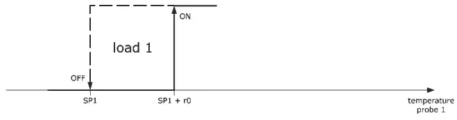
OPERATION
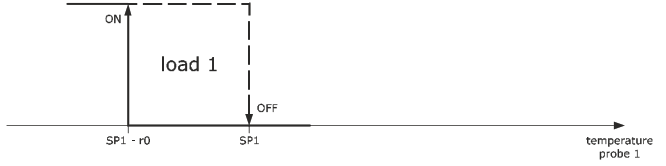
Controller with two independent regulators (P10 = 0, default)
Cold mode regulation regulator 1 (r5 = 0).
Hot mode regulation regulator 1 (r5 = 1).
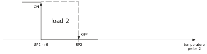
Cold mode regulation regulator 2 (r10 = 0).
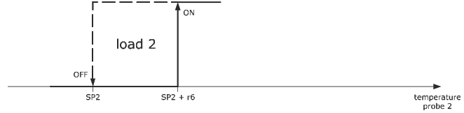
Hot mode regulation regulator 2 (r10 = 1).
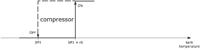
Controller for refrigerated milk storage units (P10 = 1)
Compressor operation.
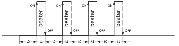
Beater operation set to t0 and t1 (r14 = 0).
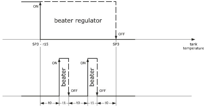
Beater operation set to r19, t0 and t1 if beater setpoint is not reached (r14 = 1).
Cold mode regulation beater (r19 = 0)
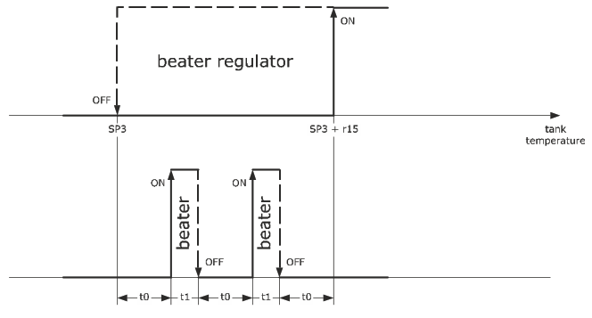
Beater operation set to r19, t0 and t1 if beater setpoint is not reached (r14 = 1).
Hot mode regulation (r19 = 1).
Controller for ice cream batch freezers (P10 = 2)
The batch freezing cycle consists of 4 phases:
- heating
- cooking
- cooling
- conservation.
Heating
The compressor remains off.
Plate heaters operation.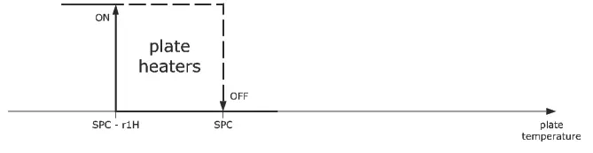 Beater operation.
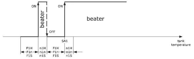 End of phase.
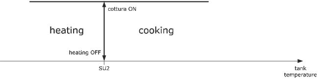
At the end of the phase the buzzer emits 10 beeps 1 s long.
If there is a power failure during the phase, it starts back up again from the beginning.
Cooking
The compressor remains off.
Plate heaters operation.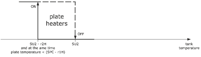 Beater operation.
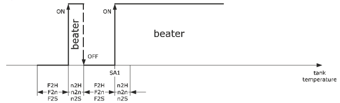
End of phase.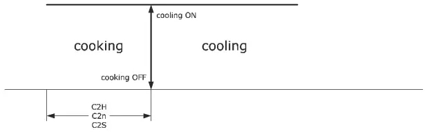 At the end of the phase the buzzer emits 10 beeps 1 s long.
If there is a power failure during the phase, it starts back up again from the beginning.
Cooling
Compressor operation.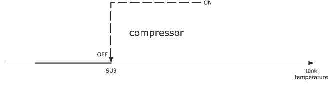 The plate heaters remain off.
Beater operation.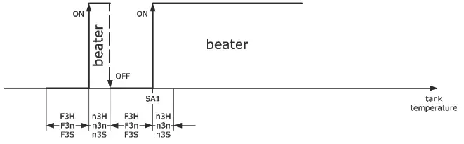
End of phase.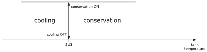 At the end of the phase the buzzer emits 10 beeps 1 s long.
If there is a power failure during the phase:
- the phase starts back up again from the beginning if (tank temperature after the powerfailure – tank temperature before the power failure) < PFd
- the cycle starts back up again from the beginning of the heating phase if (tank temperature after the power failure tank temperature before the power failure) > PFd.
Conservation
Compressor operation.
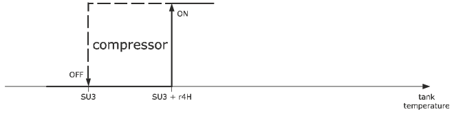
The plate heaters remain off.
Beater operation. End of phase.

If there is a power failure during the phase:
- the phase starts back up again from the beginning if (tank temperature after the power failure – tank temperature before the power failure) < PFd
- the cycle starts back up again from the beginning of the heating phase if (tank temperature after the power failure
- tank temperature before the power failure) > PFd.
ADDITIONAL FUNCTIONS
Viewing the temperatures detected by the probes
Check that the keypad is not locked.
| 1 | Touch the DOWN key for 4 s. | |
| 2 | Touch the UP or DOWN key within 15 s to select a label. | |
| LAB. | DESCRIPTION | |
| Pb1 | probe 1 temperature | |
| Pb2 | probe 2 temperature | |
| 3 | Touch the SET key. | |
| 4 | Touch the ON/STAND-BY key (or take no action for 60 s) to exit the procedure. |
SETTINGS
Setting configuration parameters
| 1 | Touch the SET key for 4 s: the display will show the label “PA”. | |
| 2 | Touch the SET key. | |
| 3 | Touch the UP or DOWN key within 15 s to set the PAS value (default “-19”). | |
| 4 | Touch the SET key (or take no action for 15 s): the display will show the label “SP1”. | |
| 5 | Touch the UP or DOWN key to select a parameter. | |
| 6 | Touch the SET key. | |
| 7 | Touch the UP or DOWN key within 15 s to set the value. | |
| 8 | Touch the SET key (or take no action for 15 s). | |
| 9 | Touch the SET key for 4 s (or take no action for 60 s) to exit the procedure. |
Restoring factory (default) settings and saving customised settings
N.B.![]()
- check that the factory settings are appropriate; see the section CONFIGURATION PARAMETERS.
- saving customised settings overwrites the factory settings.
| 1 | Touch the SET key for 4 s: the display will show the label “PA”. | |
| 2 | Touch the SET key. | |
| 3 | Touch the UP or DOWN key within 15 s to set the value. | |
| VAL. | MEANING | |
| 149 | value for restoring the factory information (default) | |
| 161 | value for saving customised settings | |
| 4 | Touch the SET key (or take no action for 15 s): the display will show the label “dEF” (for setting the “149” value) or the label “MAP” (for setting the “161” value). | |
| 5 | Touch the SET key. | |
| 6 | Touch the UP or DOWN key within 15 s to set the value. | |
| VAL. 1 | MEANING | |
| 1 | controller with two independent regulators | |
| 2 | controller for refrigerated milk storage units | |
| 3 | controller for ice cream batch freezers | |
| 7 | Touch the SET key (or take no action for 15 s): the display will show “- – -” flashing for 4 s, after which the device will exit the procedure. | |
| 8 | Disconnect the device from the power supply. | |
| 9 | Touch the SET key for 2 s before action 6 to exit the procedure beforehand. | |
CONFIGURATION PARAMETERS
| NO. | PAR. | DEF. | SETPOINT | MIN… MAX. | |
| 1 | SP1 | 0.0 | load 1 setpoint | rl… r2 | |
| 2 | SP2 | 0.0 | load 2 setpoint | r7… r8 | |
| 3 | SP3 | 0.0 | beater setpoint | r16… r17 | |
| NO. | PAR. | DEF. | ANALOGUE INPUTS | MIN… MAX. | |
| 4 | CAl | 0.0 | probe 1 offset | -25… 25 °C/°F | |
| 5 | CA2 | 0.0 | probe 2 offset | -25… 25 °C/°F | |
| 6 | PO | 1 | type of probe | 0 = PTC 1 = NTC | |
| 7 | P1 | 0 | enable decimal point °C | 0 = no 1 = yes | |
| 8 | P2 | 0 | temperature measurement unit | 0 = °C 1 = °F | |
| 9 | P3 | 2 | probe 1 function not visible if P10 = 2 | 0 = disabled 1 = tank probe 2 = regulator 1 3 = condenser probe | |
| 10 | P4 | 2 | probe 2 function not visible if PIO = 2 | 0 = disabled 1 = plate probe 2 = regulator 2 3 = condenser probe | |
| 11 | P5 | 0 | value displayed | 0 = probe 1 temperature 1 = probe 2 temperature 2 = load 1 setpoint 3 = load 2 setpoint | |
| 12 | P8 | 5 | display refresh time | 0… 250 s: 10 | |
| 13 | R | 0 | enable quick settings block | 0 = disabled 1 = setpoint 2 = beater on/off times 3 = beater on/off setpoint + times | |
| 14 | P10 | 0 | operating logic | 0 = controller with two inde- pendent regulators 1 = controller for refrigerated milk storage units 2 = controller for ice cream batch freezers |
| NO. | PAR. | DEF. | REGULATION | MIN… MAX. | |
| 15 | r0 | 2.0 | load 1 setpoint differential | 1… 15 °C/°F | |
| 16 | rl | -50 | load 1 minimum setpoint | -99 °C/°F… r2 | |
| 17 | r2 | 500 | load 1 maximum setpoint | rl… 150 °C/°F | |
| 18 | r5 | 0 | hot or cold mode regulation regu- lator 1 | 0 = cold mode 1 = hot mode | |
| 19 | r6 | 2.0 | load 2 setpoint differential | 1… 15 °C/°F | |
| 20 | r7 | -50 | load 2 minimum setpoint | -99 °C/°F… r8 | |
| 21 | r8 | 500 | load 2 maximum setpoint | r7… 150 °C/°F | |
| 22 | r9 | 1 | enable regulator 2 | 0 = no 1 = yes if P10 = 1 | |
| 23 | r10 | 0 | hot or cold mode regulation regu- lator 2 | 0 = cold mode 1 = hot mode | |
| 24 | r14 | 0 | beater mode in normal operation | 0 = parameter set to tO and tl 1 = parameter set to r19, tO, ti if the beater setpoint is not reached | |
| 25 | r15 | 0.5 | beater setpoint differential | 1… 15 °C/°F | |
| 26 | r16 | -50 | beater minimum setpoint | -99 °C/°F… r17 | |
| 27 | r17 | 50 | beater maximum setpoint | r16… 150 °C/°F | |
| 28 | r19 | 0 | hot or cold mode regulation beater | 0 = cold mode 1 = hot mode | |
| 29 | r20 | 0 | beater mode in beater probe alarm | 0 = off 1 = set to tO and tl | |
| 30 | r21 | 0 | constraint between beater and compressor | 0 = disabled 1 = on if compressor on and parameter set to r14 2 = on if compressor off and parameter set to r14 3 = on if compressor on |
| NO. | PAR. | DEF. | BEATER | MIN… MAX. | |
| 31 | tO | 3 | beater off time | 0… 240 min | |
| 32 | tl | 2 | beater on time | 0… 240 min | |
| 33 | t2 | 0 | beater off delay from compressor off | 0… 240 min | |
| 34 | t3 | 10 | minimum beater on and off time | 0… 240 s | |
| NO. | PAR. | DEF. | LOADS | MIN… MAX. | |
| 35 | CO | 3 | load 1 on delay from power-on | 0… 240 min | |
| 36 | Cl | 5 | delay between two load 1 switch- ons | 0… 240 min | |
| 37 | C2 | 3 | load 1 minimum off time | 0… 240 min | |
| 38 | C3 | 0 | load 1 minimum on time | 0… 240 s | |
| 39 | C4 | 10 | load 1 off time in probe 1 alarm | 0… 240 min if C6 = 2 | |
| 40 | C5 | 15 | load 1 on time in probe 1 alarm | 0… 240 min if C6 = 2 | |
| 41 | C6 | 3 | load 2 on delay from power-on and load 2 minimum off time | 0… 240 min | |
| 42 | C7 | 2 | load 2 minimum on time | 0… 240 s | |
| 43 | C8 | 5 | delay between two load 2 switch- ons | 0… 240 min | |
| 44 | C10 | 10 | load 2 off time in probe 2 alarm | 0… 240 min if C6 = 2 | |
| 45 | C11 | 15 | load 2 on time in probe 2 alarm | 0… 240 min if C6 = 2 |
| 46 | C13 | 80.0 | high condensation signal thresh- old not visible if P10 = 2 | 0… 199 °C/°F differential = 2 °C/4 °F | |
| 47 | C14 | 90.0 | high condensation alarm thresh- old | 0… 150 °C/°F | |
| 48 | C15 | 60 | high condensation alarm delay | 0… 240 s | |
| NO. | PAR. | DEF. | DEFROSTING (if r5 = 0) | MIN… MAX. | |
| 49 | dO | 8 | automatic defrost interval regula- for 1 and regulator 2 | 0… 99 h 0 = manual only | |
| 50 | d3 | 30 | defrost duration regulator 1 | 0… 99 min | |
| 51 | d4 | 0 | enable defrost at power-on | 0 = no 1 = yes | |
| 52 | d5 | 0 | defrost delay from power-on | 0… 99 min | |
| 53 | d6 | 2 | value displayed when defrosting | 0 = value P5 (if P5 = 0 or 1) 1 = value P5 (if P5 = 0 or 1) at defrost activation 2 = label dEF | |
| 54 | d10 | 30 | defrost duration regulator 2 | 0… 99 min | |
| 55 | d12 | 0 | constraint between defrost regu- lator 1 and defrost regulator 2 | 0 = disabled 1 = regulator defrost is acti- vated only if defrost of the other regulator is not in progress. If it is, it waits for this to end. |
| NO. | PAR. | DEF. | ALARMS | MIN… MAX. | |
| 56 | Al | –10.0 | low temperature alarm threshold probe 1 | -99… 150 °C/°F | |
| 57 | A2 | 1 | type of low temperature alarm probe 1 | 0 = disabled 1 = relative to load 1 setpoint 2 = absolute | |
| 58 | A4 | 10.0 | high temperature alarm threshold probe 1 | -99… 150 °C/°F | |
| 59 | AS | 1 | type of high temperature alarm probe 1 | 0 = disabled 1 = relative to load 1 setpoint 2 = absolute | |
| 60 | A6 | 12 | high temperature alarm delay probe 1 from power-on | 0… 99 minx10 | |
| 61 | A7 | 15 | high/low temperature alarm delay probe 1 | 0… 240 min | |
| 62 | AS | 15 | high temperature alarm delay probe 1 after defrosting regulator 1 | 0… 240 min | |
| 63 | A10 | – – – | unused | ||
| 64 | All | –10.0 | low temperature alarm threshold probe 2 | -99… 150 °C/°F | |
| 65 | Al2 | 1 | type of low temperature alarm probe 2 | 0 = disabled 1 = relative to load 2 setpoint 2 = absolute | |
| 66 | A14 | 10.0 | high temperature alarm threshold probe 2 | -99… 150 °C/°F | |
| 67 | A15 | 1 | type of high temperature alarm probe 2 | 0 = disabled 1 = relative to load 2 setpoint 2 = absolute | |
| 68 | A16 | 12 | high temperature alarm delay probe 2 from power-on | 0… 99 minx10 | |
| 69 | A17 | 15 | high/low temperature alarm delay probe 2 | 0… 240 min | |
| 70 | A18 | 15 | high temperature alarm delay probe 2 after defrosting regulator 2 | 0… 240 min | |
| 71 | A19 | 2.0 | high/low temperature alarm reset differential | 1… 15 °C/°F |
| NO. | PAR. | DEF. | DIGITAL INPUTS | MIN… MAX. | |
| 72 | i2 | 0 | door switch/multi-purpose input alarm signal delay | 0… 120 min | |
| 73 | i3 | 0 | maximum compressor and beater off time with door switch/multipurpose input active | 0… 120 min | |
| 74 | i7 | 0 | door switch/multi-purpose input alarm activation delay | 0… 120 min | |
| 75 | i5 | 0 | door switch/multi-purpose input function | 0 = disabled 1 = compressor off 2 = beater off 3 = multi-purpose input alarm 4 = switches device on/off 5 = thermal switch alarm 6 = door open alarm | |
| 76 | i6 | 0 | activation door switch/multi-pur- pose input | 0 = with contact closed 1 = with contact open | |
| NO. | PAR. | DEF. | DIGITAL OUTPUTS | MIN… MAX. | |
| 77 | u1 | 3 | K1 relay configuration | 0 = compressor 1 = plate heaters 2 = beater 3 = load 1 4 = load 2 5 = alarm | |
| 78 | u2 | 4 | K2 relay configuration | as ul | |
| 79 | u3 | 5 | K3 relay configuration | as ul | |
| 80 | u4 | 1 | enable silencing alarm output | 0 = no 1 = yes |
| NO. | PAR. | DEF. | BATCH FREEZER | MIN… MAX. | |
| 81 | Snd | -50 | threshold for neutral zone regula- tion during cooking | 99… 150 °C/°F | |
| 82 | d2n | 1.0 | neutral zone value | 0… 99.0 °C/°F | |
| 83 | r23 | 0.0 | minimum plate setpoint during batch freezing heating and cooking | 0 °C/°F… r24 | |
| 84 | r24 | 130 | maximum plate setpoint during batch freezing heating and cooking | r23… 150 °C/°F | |
| 85 | r25 | 0.0 | minimum tank setpoint at end of batch freezing heating and batch freezing cooking setpoint | 0 0C/0F… r26 | |
| 86 | r26 | pO O | maximum tank setpoint at end of batch freezing heating and bat& freezing cooking setpoint | r25… 150 °C/°F | |
| 87 | r27 | 0.0 | minimum tank setpoint at end of batch freezing cooling and tank setpoint during conservation | -2 0C/0F… r28 | |
| 88 | r28 | 130 | maximum tank setpoint at end of batch freezing cooling and tank setpoint during conservation | r27… 60 0C/°F | |
| 89 | SAl | 50.0 | tank setpoint for beater on or on/off during batch freezing | -99… 150 0C/°F differential = 5 0C/10 of | |
| 90 | PFd | 5.0 | difference in tank temperature af- ter power failure during batch freezing cooling or conservation due to reactivating heating | 1… 25 °C/°F | |
| NO. | PAR. | DEF. | BATCH FREEZING HEATING | MIN… MAX. | |
| P 1 | OH | 2.0 | plate differential setpoint during batch freezing heating and plate setpoint during batch freezing cooking | 1… 25 °C/°F | |
| 92 | 1Z1freezing n1H | 0 | hours beater on during batch heating | 0… 23 h | |
| 93 | nln | 2 | minutes beater on during batch freezing heating | 0… 59 min | |
| 94 | n1S | 0 | seconds beater on during batch freezing heating | 0… 59 s | |
| 95 | FIH | 0 | hours beater off during batch freezing heating | 0… 23 h | |
| 96 | F1n | 2 | minutes beater off during batch freezing heating | 0… 59 min |
EVCO S.p.A. | EV3143 | Instruction sheet ver. 1.0 | Code 1043143E103 | Page 3 of 3 | PT 22/19
| 97 | F1S | 0 | seconds beater off during batch freezing heating | 0… 59 s | |
| NO. | PAR. | DEF. | BATCH FREEZING COOKING | MIN… MAX. | |
| 98 | SPC | 30.0 | plate setpoint during batch freez- ing cooking and plate setpoint during batch freezing cooking | r23… r24 | |
| 99 | SU2 | 30.0 | tank setpoint at end of batch freezing heating and tank setpoint during batch freezing cooking | r25… r26 | |
| 100 | r2H | 2.0 | tank differential setpoint during batch freezing cooking | 1… 25 °C/°F | |
| 101 | C2H | 1 | duration in hours of batch freezing cooking | 0… 23 h | |
| 102 | C2n | 0 | duration in minutes of batch freezing cooking | 0… 59 min | |
| 103 | C2S | 0 | duration in seconds of batch freezing cooking | 0… 59 s | |
| 104 | n2H | 0 | hours beater on during batch freezing cooking | 0… 23 h | |
| 105 | n2n | 2 | minutes beater on during batch freezing cooking | 0… 59 min | |
| 106 | n2S | 0 | seconds beater on during batch freezing cooking | 0… 59 s | |
| 107 | F2H | 0 | hours beater off during batch freezing cooking | 0… 23 h | |
| 108 | F2n | 2 | minutes beater off during batch freezing cooking | 0… 59 min | |
| 109 | F2S | 0 | seconds beater off during batch freezing cooking | 0… 59 s |
| NO. | PAR. | DEF. | BATCH FREEZING COOLING | MIN… MAX. | |
| 110 | SU3 | 30.0 | tank setpoint at end of batch freezing cooling and tank setpoint during batch freezing conservation | r27… r28 | |
| 111 | SA3 | 10.0 | tank setpoint for beater on at end of batch freezing cooking | 0… 25 °C/°F | |
| 112 | ZIfreezing n3H | 0 | hours beater on during batch cooling | 0… 23 h | |
| 113 | n3n | 2 | minutes beater on during batch freezing cooling | 0… 59 min | |
| 114 | n3S | 0 | seconds beater on during batch freezing cooling | 0… 59 s | |
| 115 | F3H | 0 | hours beater off during batch freezing cooling | 0… 23 h | |
| 116 | F3n | 2 | minutes beater off during batch freezing cooling | 0… 59 min | |
| 117 | F3S | 0 | seconds beater off during batch freezing cooling | 0… 59 s | |
| NO. | PAR. | DEF. | BATCH FREEZING CONSERVA- TION | MIN… MAX. | |
| 118 | r4H | 2.0 | tank differential setpoint during batch freezing conservation | 1… 25 °C/°F | |
| 119 | n4H | 0 | hours beater on during batch freezing conservation | 0… 23 h | |
| 120 | n4n | 2 | minutes beater on during batch freezing conservation | 0… 59 min | |
| 121 | n4S | 0 | seconds beater on during batch freezing conservation | 0… 59 s | |
| 122 | F4H | 0 | hours beater off during batch freezing conservation | 0… 23 h | |
| 123 | F4n | 2 | minutes beater off during batch freezing conservation | 0… 59 min | |
| 124 | F4S | 0 | seconds beater off during batch freezing conservation | 0… 59 s | |
| 125 | F4C | 0 | beater mode during batch freezing conservation | 0 = independent on the compressor 1 = on if compressor on, according to n4… and F4… if compressor off |
| NO. | PAR. | DEF. | SECURITY | MIN… MAX. | |
| 126 | H4E | 0 | timeout for locking the keypad | 0… 240 s | |
| 127 | POF | 1 | enable ON/STAND-BY key | 0 = no 1 = yes | |
| 128 | PAS | -19 | password | -99… 999 | |
| 129 | PA1 | – – – | unused | – | |
| 130 | PA2 | – – – | unused | – | |
| NO. | PAR. | DEF. | UNUSED | MIN… MAX. | |
| 131 | Hr0 | – – – | unused | – | |
| NO. | PAR. | DEF. | UNUSED | MIN… MAX. | |
| 132 | rE0 | – – – | unused | – | |
| 133 | rEl | – – – | unused | – | |
| NO. | PAR. | DEF. | MODBUS | MIN… MAX. | |
| 134 | LA | 247 | MODBUS address | 1… 247 | |
| 135 | Lb | 2 | MODBUS baud rate | 0 = 2,400 baud 1 = 4,800 baud 2 = 9,600 baud 3 = 19,200 baud | |
| 136 | bLE | – – – | unused | – | |
| NO. | PAR. | DEF. | SECURITY | MIN… MAX. | |
| 137 | bul | 0 | duration of buzzer activation when setpoint reached | 0… 240 s | |
| 138 | Pbu | 2 | enable buzzer | 0 = disabled 1 = keys only 2 = alarms only 3 = keys and alarms |
ALARMS
| CODE | DESCRIPTION | RESET | TO CORRECT |
| Pr1 | probe 1 alarm | automatic | – check PO – check integrity of the probe – check electrical connection |
| Pr2 | probe 2 alarm | automatic | |
| rtc | unused | unused | unused |
| All | low-temperature alarm probe 1 | automatic | check Al and A2 |
| AH1 | high-temperature alarm probe 1 | automatic | check A4 and AS |
| AL2 | low-temperature alarm probe 2 | automatic | check All and Al2 |
| AH2 | high-temperature alarm probe 2 | automatic | check A14 and A15 |
| id | door open alarm | automatic | check i5 and i6 |
| PF | power failure alarm | manual | – touch a key – check electrical connection |
| COH | high condensation signal | automatic | check C13 |
| CSd | high condensation alarm | manual | – switch the device off and on – check C14 |
| iA | multi-purpose input alarm | automatic | check i5 and i6 |
| it | thermal switch alarm | automatic | – switch the device off and on – check i5 and i6 |
TECHNICAL SPECIFICATIONS
| Purpose of the control device: | function controller. |
| Construction of the control device: | built-in electronic device. |
| Housing: | black, self-extinguishing. |
| Category of heat and fire resistance: | D. |
| Measurements: | |
| 75.0 x 33.0 x 59.0 mm (2 15/16 x 1 5/16 x 2 5/16 in) with fixed screw terminal blocks | 75.0 x 33.0 x 81.5 mm (2 15/16 x 1 5/16 x 3 3/16 in) with plug-in screw terminal blocks |
| Mounting methods for the control device: | to be fitted to a panel, snap-in brackets provided |
| Degree of protection provided by the casing: | IP65 (front). |
| Connection method: | ||
| fixed screw terminal blocks for wires up to 2.5 mm² | plug-in screw terminal blocks for wires up to 2.5 mm² (on request) | Micro-MaTch connector |
| Maximum permitted length for connection cables: |
| power supply: 10 m (32.8 ft) | analogue inputs: 10 m (32.8 ft) |
| digital inputs: 10 m (32.8 ft) | digital outputs: 10 m (32.8 ft). |
| Operating temperature: | from 0 to 55 °C (from 32 to 131 °F). |
| Storage temperature: | from -25 to 70 °C (from -13 to 158 °F). |
| Operating humidity: | relative humidity without condensate from 10 to 90%. |
| Pollution status of the control device: | 2 |
| Compliance: | ||
| RoHS 2011/65/EC | WEEE 2012/19/EU | REACH (EC) Regulation no. 1907/2006 |
| EMC 2014/30/EU | LVD 2014/35/EU. |
| Power supply: |
| 230 VAC (+10% -15%), 50/60 Hz (±3 Hz), max. 2 VA insulated in EV3143N7 |
| 115 VAC (+10% -15%), 50/60 Hz (±3 Hz), max. 2 VA insulated in EV3143N5. |
| Earthing methods for the control device: | none. |
| Rated impulse-withstand voltage: | 4 KV. |
| Over-voltage category: | III. |
| Software class and structure: | A. |
| Analogue inputs: | 2 for PTC or NTC probes (probe 1 and probe 2). |
| PTC probes: | Type of sensor: | KTY 81-121 (990 W @ 25 °C, 77 °F) |
| Measurement field: | from -50 to 150 °C (from -58 to 302 °F) | |
| Resolution: | 0.1 °C (1 °F). | |
| NTC probes: | Type of sensor: | ß3435 (10 KW @ 25 °C, 77 °F) |
| Measurement field: | from -40 to 105 °C (from -40 to 221 °F) | |
| Resolution: | 0.1 °C (1 °F). |
| Digital inputs: | 1 dry contact (door switch/multi-purpose). |
| Dry contact: | Type of contact: | 5 VDC, 1.5 mA |
| Power supply: | none | |
| Protection: | none. |
| Digital outputs: | 3 electromechanical relays. |
| K1 relay: | SPST, 16 A res. @ 250 VAC |
| K2 relay: | SPDT, 8 A res. @ 250 VAC. |
| K3 relay: | SPST, 5 A res. @ 250 VAC. |
| Type 1 or Type 2 actions: | type 1. |
| Additional features of Type 1 or Type 2 actions: | C. |
| Displays: | custom display, 3 digits, with function icons. |
| Alarm buzzer: | built-in. |
| Communications ports: | 1 TTL MODBUS slave port for BMS. |
N.B.![]() The device must be disposed of according to local regulations governing the collection of electrical and electronic equipment.
The device must be disposed of according to local regulations governing the collection of electrical and electronic equipment.
This document and the solutions contained therein are the intellectual property of EVCO and thus protected by the Italian Intellectual Property Rights Code (CPI). EVCO imposes an absolute ban on the full or partial reproduction and disclosure of the content other than with the express approval of EVCO. The customer (manufacturer, installer, or end-user) assumes all responsibility for the configuration of the device. EVCO accepts no liability for any possible errors in this document and reserves the right to make any changes at any time without prejudice to the essential functions and safety features of the equipment.
![]()
EVCO S.p.A.
Via Feltre 81, 32036 Sedico (BL) ITALY
Tel. +39 0437/8422 | Fax +39 0437/83648
email [email protected] | web www.evco.it


