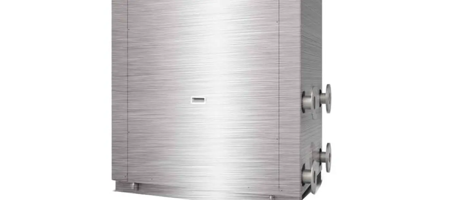
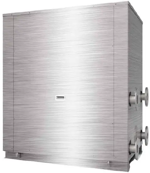
EVOHEAT Evo Ultra Series
Introduction
This manual contains all the necessary information in regard to the installation, troubleshooting, operation and maintenance of this unit. Ensure instructions in this manual are adhered to at all times. Failing to comply with these recommendations will invalidate the warranty. This manual and all others are available for download on our website.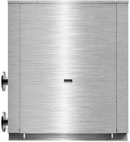 The Evo Ultra is our water to water heat pump that is the perfect solution in applications where chillers and cooling towers are being used for temperature control. When installed in line with the chiller, the Evo Ultra can capture rejected waste from the chiller return lines and utilize this heat to provide FREE HOT WATER!
- Bulk hot water up to 80 degrees
- Provides fast, stable hot water in climates -7°C to 45°C
- Extremely energy efficient
- Connect to your cooling tower to benefit from FREE HOT WATER
- Market leading protection features
- Reduces energy use and green house gases
- 304 stainless steel cabinet
Unit Specifications
Dimensions
EVO ULTRA 32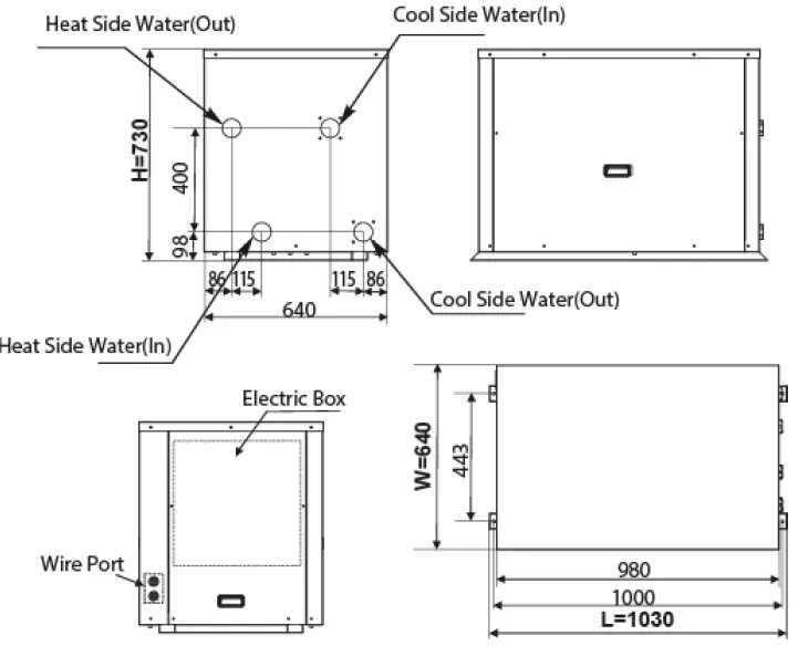
 EVO ULTRA 64
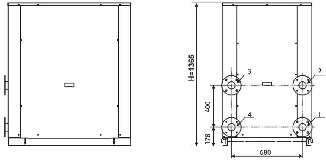
 EVO ULTRA 129
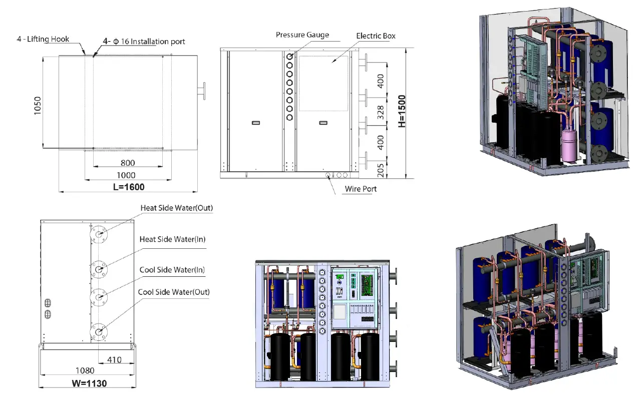
Operational Principle
According to Reverse Carnot Cycle theory and the same process as normal water source heat pump units, The Evo Ultra absorbs heat from soil and transfers the heat to water as the soil temperature is generally stable, i.e., the heat source is stable, the units work capability will not change with the ambient temperature.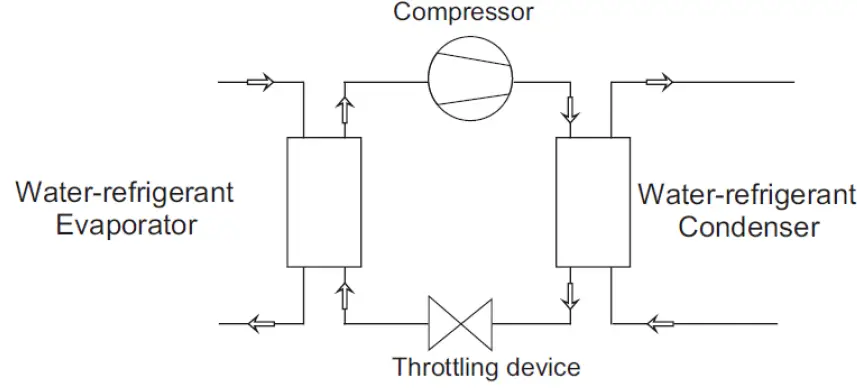
Technical Data
| Model | Evo Ultra | 32 | 64 | 129 | |
| Heating | Heating Capacity | kW | 32.3 | 64 | 129 |
| kcal/h | 27810 | 55900 | 111000 | ||
| Cooling Capacity | kW | 19.8 | 40 | 80 | |
| kcal/h | 17048 | 34400 | 68000 | ||
| Input Power | kW | 10 | 20 | 40 | |
| Input Current | A | 18.2 | 35.2 | 71 | |
| Power Supply | / | / | 380V/3N~/50Hz | 380V/3N~/50Hz | 380V/3N~/50Hz |
| Compressor | Type | / | EVI Scroll | EVI Scroll | EVI Scroll |
| Quantity | / | 1 | 2 | 4 | |
| Heat Source Side Head Exchanger | Type | / | Tube in Shell HX | Tube in Shell HX | Tube in Shell HX |
| Water flow rate | M3/h | 2.7 | 5.6 | 11.1 | |
| Water pressure drop | kPa | 34 | 45 | 23 | |
| Water (in) connection | / | DN32 | DN65 | DN65 | |
| Water (out) connection | / | DN32 | DN65 | DN65 | |
| Cool Source Side Heat Exchanger | Type | / | Tube in Shell HX | Tube in Shell HX | Tube in Shell HX |
| Water flow rate | M3/h | 3.5 | 6.8 | 13.6 | |
| Water pressure drop | kPa | 13 | 23 | 45 | |
| Water (in) Connection | / | DN32 | DN65 | DN65 | |
| Water (out) Connection | / | DN32 | DN65 | DN65 | |
| Noise | dB (A) | 55 | 56 | 58 | |
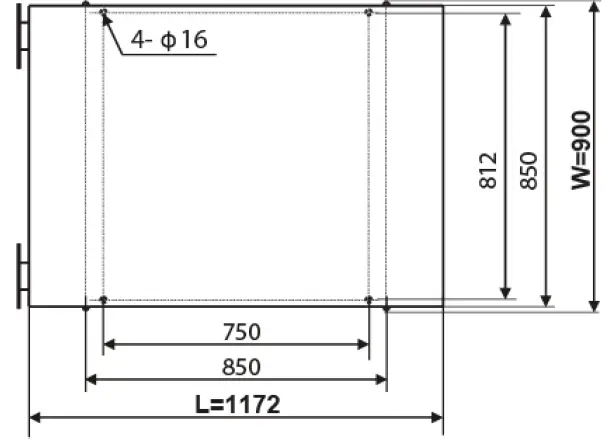
| Unit Dimension (L/W/H) | mm | 1030/640/730 | 1172/900/1365 | 1600/1130/1500 | |
| Unit Weight | kg | 219 | 841 | 925 | |
Heating:
- Heat source side: water inlet/outlet temperature: 20°C/15°C
- User side water inlet/outlet temperature: 65°C/75°C
- When the units work between 55-85°C, make sure the low-pressure range is between 0.27-0.65MPa and the evaporating temperature is between 7-30°C.
- The above data is for reference only, specific data is subject to the product nameplate.
Safety Instructions
- Installation, repair or relocations must be done by a fully qualified person and not by the customer. If done incorrectly it may cause fire, electric shock, water leakage and other hazards.
- Maintenance and operation must be carried out according to the recommended time and frequencies, as stated in this manual.
- To avoid risk of electrical shock, the unit must have a good power connection and earthing.
- Use genuine standard spare parts only.
- When an abnormality (smell of burning, etc.) occurs, stop the unit and disconnect the power or turn off the breaker. If the unit continues to be operated in an abnormal condition, it may cause a fire or hazards.
- Do not insert fingers or objects into the fans or evaporator of the unit.
- You should have a program to ensure personal safety in the case of a refrigerant leak when the unit is installed in a small room.
- For unit cleaning or maintenance, switch off and disconnect the power of the unit.
- Do not install the unit near flammable gas or spray flammable substances near it.
Installation
Installation Notes
- Choose the right product model according to climate, architecture and insulation situation.
- Read the product user guide before installation and clearly understand what each label means. Please install, test and maintain the units according to the user guide.
- Check every attachment in case of omission.
- This model can be installed on a concrete base with expansion bolts or installed on the ground or roof by a steel bracket with rubber cushion. Make sure that the units are horizontally placed.
- The units should be installed at a place convenient for installation and maintenance.
- The units should install shock-absorbing devices in case of the shock transferring to the building.
- Rigid pipelines in the engine room should adopt spring shock-absorbing brackets.
- Units should be installed indoors or outdoors with a shelter.
- Units should be installed somewhere with no radiation or other heat sources.
Transit
Use four slings longer than 8m when moving the units and use the lifting holes on the bottom board. Put a cushion block at the places of contact in case of damage.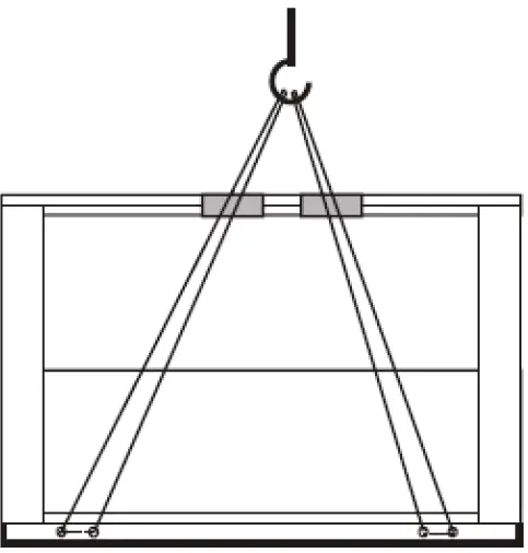
Water Pipeline Connection
When connecting the water pipeline, you cannot exchange the user side pipeline with the heat source side pipeline. The unit’s user side and heat source side direction should be in accordance with the direction as marked on the units. Water pipeline resistance out of the units should as minimal as possible. The pipeline must be clean to prevent jamming. Before packing the insulation layer, a leakage test should be conducted. Adopt the same diameter water pipe as mentioned in the user guide for inlet and outlet connection pipe out of the units. Ensure that the pipeline is full of water and has fine moisture measures when the unit is at work. The Expansion water tank should be equipped at the highest part of the water pipeline. The water surface of the expansion water tank should be 0.5m or higher than the highest point of water pipeline.
Choose the insulation water tank with suitable volume according to the units heating and cooling capacity and ensure the insulation of pipeline out of the water tank.
If the units have no water pump equipped, please choose the proper water pump according to the units water flow volume on the user guide, making sure the water flow volume satisfies the units requirement. There should be hose connection equipment between the water pump and units. If the water pump is installed outdoors, there should be water-proof and anti-freezing equipment. An automatic exhaust air valve should be equipped at the highest point of the water pipeline in case of air detention in the pipe; Drainage valve should be equipped at the lowest point of the water pipeline, so it can be convenient for maintenance and drainage. A Y-type filter should be installed at the circular water pump inlet port of the user side and heat source side in case that impurities may damage the units. The Y-type filter should be detachable for cleansing and maintenance. Softened water can be better for circular water. The connection of the water inlet and outlet should be flexible to reduce vibration. Drain out the water in the pipeline when you will not use the units for a long time in case of freezing. Do not change the set return water temperature and water tank insulation temperature.
Thermometer and water pressure gauge should be equipped at the units water inlet and outlet port for checking. User side water should be tap water and the hardness should be less than 20. If not, install an electric hydro treater at the tap water side.
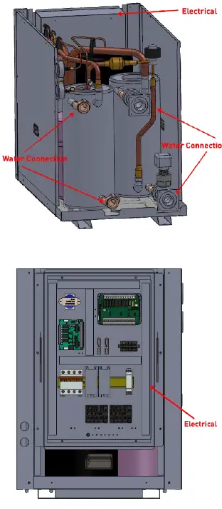
Power Supply Connection
- Open the front panel and open the power supply access.
- The power supply must go through the wire access and be connected to the power supply terminals in the controlling box. Then connect the 3-signal wire plugs of the wire controller and main controller.
- If an external water pump is required, please insert the power supply wire into the wire access and connect it to the water pump terminals.
- If an additional auxiliary heater is needed to be controlled by the heat pump controller, the relay (or power) of the aux-heater must be connected to the relevant output of the controller.
Trial Operation
Inspection before trial running
- Check the indoor unit, make sure that the pipe connection is done correctly, and the relevant valves are open.
- Check the water loop to ensure that the water inside of the expansion tank is filled to an appropriate level, the water supply is working and that the water loop is full of water & free of trapped air. Make sure there is good insulation for the water pipe.
- Check the electrical wiring. Make sure that the power voltage is normal, the screws are fastened, the wiring is made in line with the diagram and that the earthing is connected.
- Check that the heat pump includes all the screws and components, and that they are in good order. When powering the unit on, review the indicator on the controller to see if there is any indication of failure. The gas gauge can be connected to the check valve to see the high pressure (or low pressure) of the system during trial running.
Trial Operation
- Start the heat pump by pressing the ON/OFF key on the controller. Check whether the water pump is running, if it runs normally there will be 0.2MPa on the water pressure meter.
- When the water pump has ran for a minute, the compressor will start. Listen for any strange sounds from the compressor, if an abnormal sound occurs please stop the unit and check the compressor. If the compressor runs well, please look for the pressure meter of the refrigerant.
- Check whether the power input and running current is in line with the manual. If not, please stop and check.
- Adjust the valved on the water loop to make sure that the hot (cool) water supply to each door is good and meets the requirements of heating (or cooling).
- Review whether the outlet water temperature is stable.
- The parameters of the controller are set by the factory, the user cannot change these themselves.
Operation
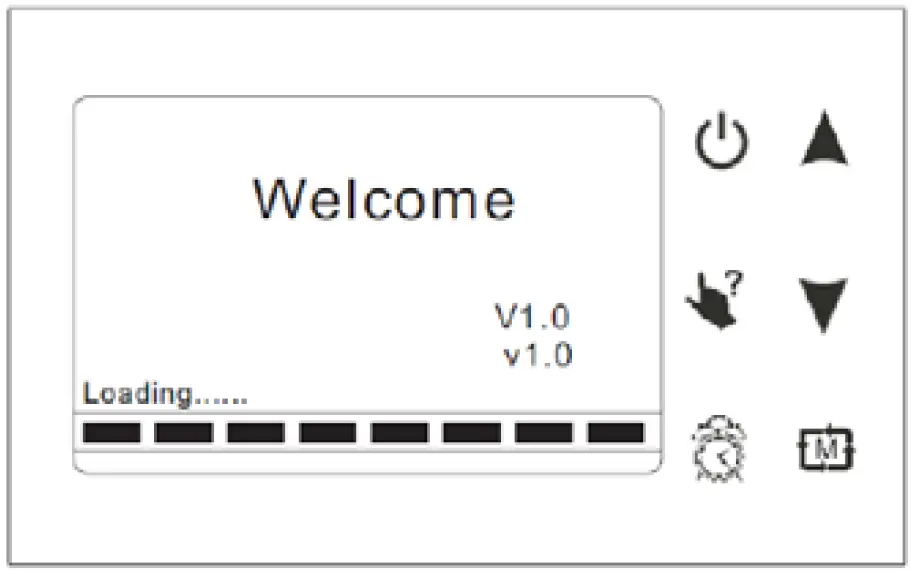
Main Controller Interface

| Button | Name | Function |
 | ON/OFF | Press this button to start up/shut off the unit, cancel current operation or go back to previous interface. |
 | HELP | Press this button to check button function of system state. |
 | MODE | Press this button to change the current mode, page up or confirm current operation. |
 | CLOCK | Press this button to set the clock or turn the timer on/off. |
 | UP | Press this key to select the upwards option or increase the parameter value. |
 | DOWN | Press this key to select the downwards option or decrease the parameter value. |
Functions of the Controller
Using the HELP Button
You can use at any interface and it will explain the buttons & functions of the current interface. To exit the help interface, simply press the ON/OFF button.
EXAMPLE: Press HELP at the Main Interface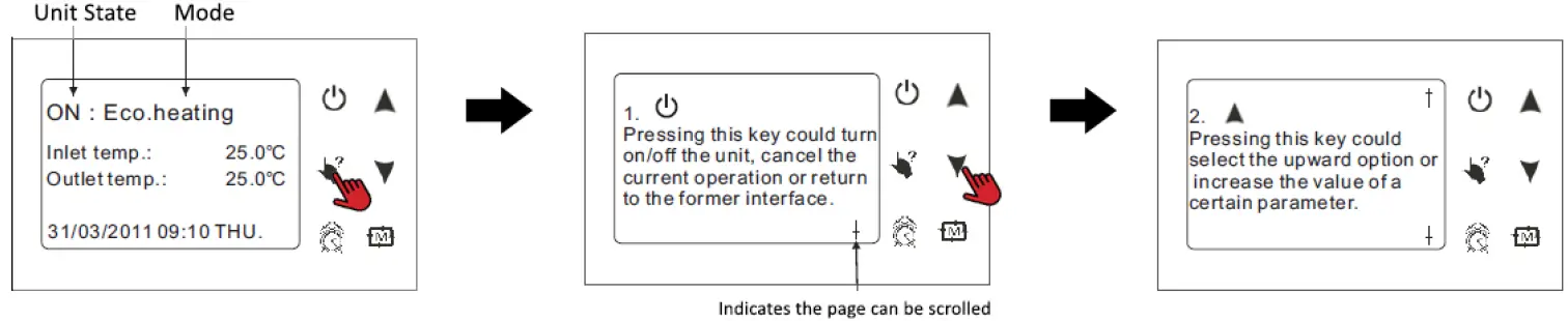 Starting & Shutting Down
To turn on/off the unit, press the ON/OFF button for 1 second. The screen will display as following for each state: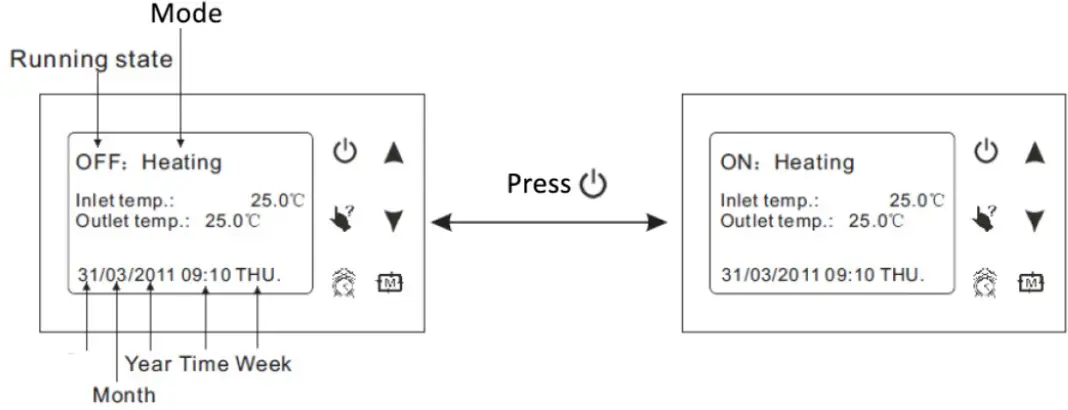 Switching Modes
At the main interface, you can switch between the modes of cooling, economic heating, heating & rapid heating by pressing . Example: Switch from Cooling mode to Economic Heating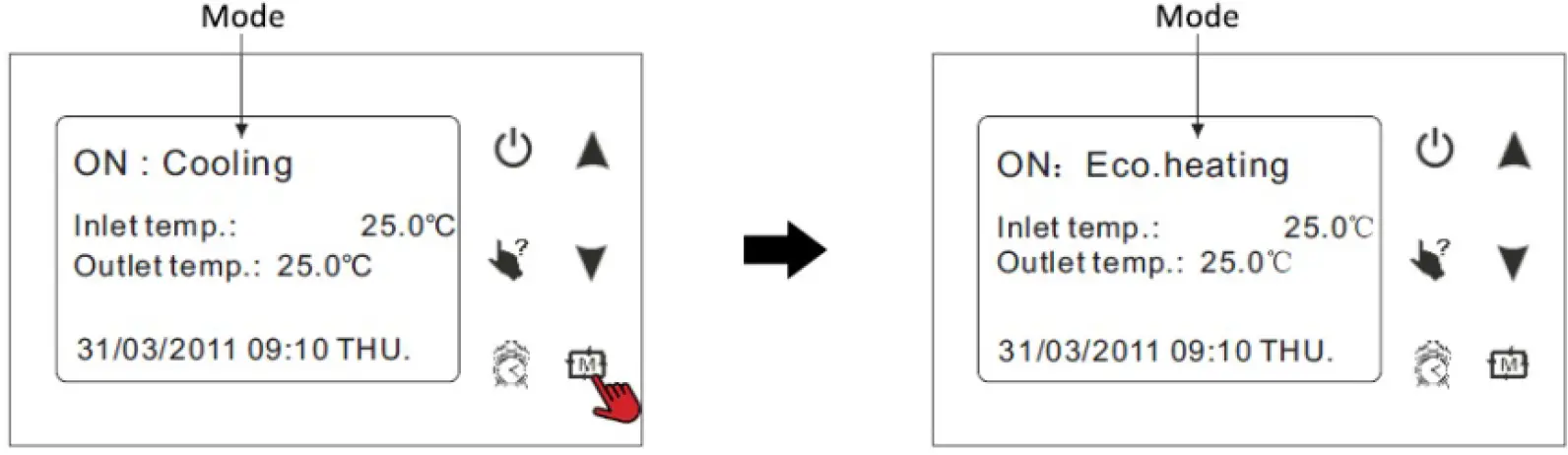 Note:
Note:
The operation of mode is invalid if the unit you purchase is heating only or cooling only.
System State Checking
At any interface you can enter the system working state by pressing TWICE, then using the UP and Down arrow keys to highlight the required parameter, then press to enter. To exit, press the ON/OFF button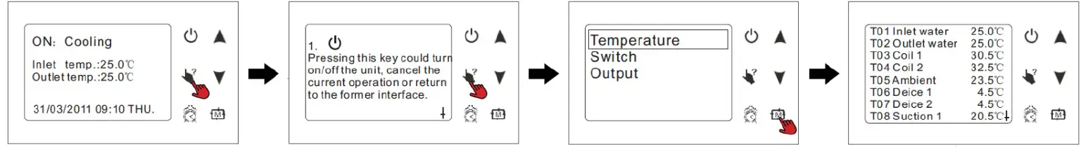 Changing Temperature
At the main interface, press the UP or DOWN key to adjust the temperature setting as desired. Once complete, press the button to save the settings and exit. Press the ON/OFF button to exit without saving settings. Refer to the Parameter Table to set relevant temperature.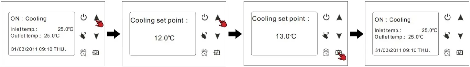 Clock Setting
At the main interface press to enter the clock setting interface. Select the parameter you wish to change and press to make the parameter begin flashing which indicates it can be changed. Press the UP or DOWN keys to change the parameter value, then press to save. Press the ON/OFF button to return to the main menu.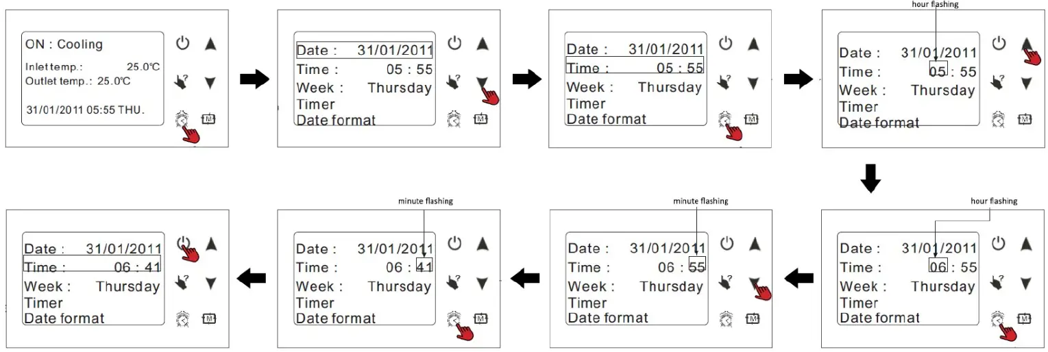 Note:
Note:
If there is no operation after 10 seconds, it will return to the main menu and changes will automatically be saved. To change the date, the same process is followed.
Timer Settings
Four timer periods can be set according to your needs. From the main interface, press to enter the timer setting, press DOWN to select Timer, then press to enter the timer setting interface. The process is much the same as adjusting the Clock settings. To cancel and return to the previous menu, press the ON/OFF button.
Timer
Each timer has an ON value when the unit will turn on an OFF value when the unit will turn off (00:00-00:00).
These timers are required for the Daily Timers & Temperature Timers to work.
Example: TIMER1 Unit is on at 7:30am – and off at 10pm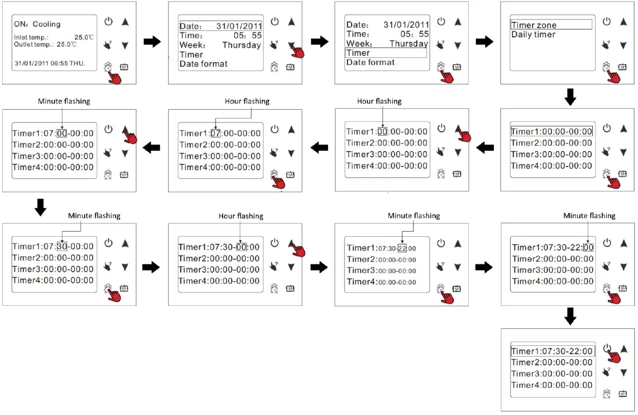 Daily Timer
The Daily Timer allows you to apply your timers to particular days of the week.
- OFF means that the unit will not run on that day.
- ON means the system will be running for a whole day.
- Applying one timer will have the unit run from A-B.
- Applying two timers will mean the unit runs from A-B, then C-D.
Example:
Setting the operation on Friday to run two different timers.
If the Timer2 were 8am-10am & Timer 3 were 1pm-5pm, the unit would operate or stop accordingly.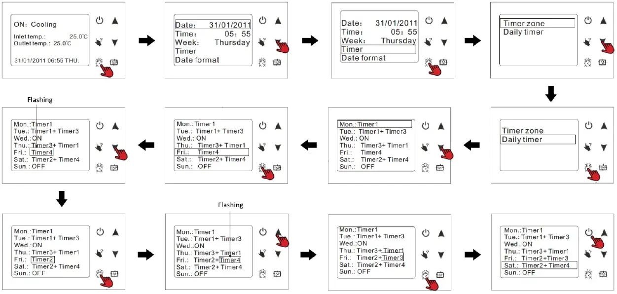 Keyboard Lock
To lock the controller after adjusting settings, at the main interface hold the ON/OFF button for 5 seconds. The keyboard will be locked and display a lock symbol on the screen. To unlock the screen, hold the ON/OFF button for 5 seconds. Note: If the unit is in alarm state, the keyboard lock is automatically removed.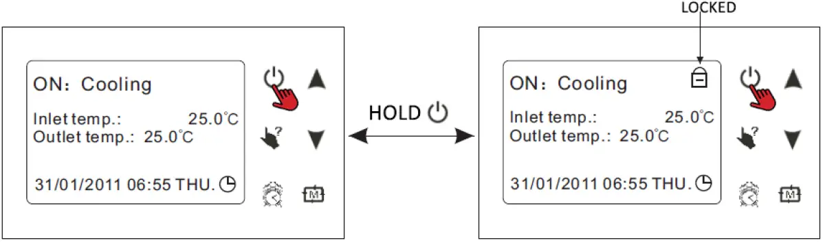 Malfunction Display
If a fault occurs, there will be a malfunction code showing on the controller screen. Refer to the Malfunction Table (9.9) to find out the failure cause and solutions.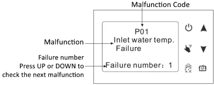
Troubleshooting
Fault Table
| Malfunction | Display | Reason | Resolution |
| Power On | |||
| Normal Working | |||
| Inlet temp. sensor failure | P01 | The temp. sensor is short circuit or broken | Check or change the temp sensor |
| Outlet temp. sensor failure | P02 | The temp. sensor is short circuit or broken | Check or change the temp sensor |
| Ambient temp. failure | P04 | The temp. sensor is short circuit or broken | Check or change the temp sensor |
| System 1/2/3/4 Coil temp. failure | P15(system1), P25(system2), P35(system3), P45(system4) | The temp. sensor is short circuit or broken | Check or change the temp sensor |
| System 1/2/3/4 absorb temp. failure | P17(system1), P27(system2), P37(system3), P47(system4) | The temp. sensor is short circuit or broken | Check or change the temp sensor |
| System 1/2/3/4 anti- freeze temp. failure | P19(system1), P29(system2), P39(system3), P49(system4) | The temp. sensor is short circuit or broken | Check or change the temp sensor |
| Using side system 1/2/3/4 Anti-freeze temp. failure | P191(system1), P291(system2), P391(system3), P491(system4) | The temp. sensor is short circuit or broken | Check or change the temp sensor |
| System 1/2/3/4 coil inlet temp. failure | P151(system1), P251(system2), P351(system3), P451(system4) | The temp. sensor is short circuit or broken | Check or change the temp sensor |
| System 1/2/3/4 high pressure protection | E11(system1), E21(system2), P31(system3), E41(system4) | The high-pressure switch is broken | Check the pressure switch and cold circuit |
| System 1/2/3/4 low pressure protection | E12(system1), E22(system2), E32(system3), E42(system4) | The low-pressure switch is broken | Check the pressure switch and cold circuit |
| Water flow failure | E03 | No water/little water in water system | Check the pipe waterflow and water pump |
| Electric-heater overheat protection | E04 | Electrical-heat is overheat | Check or change electrical-heat |
| Water inlet and outlet temp. too big | E06 | Water flow is not enough and low differential pressure | Check the pipe waterflow and whether water system is jammed or not |
| System 1/2/3/4 anti- freeze protection | E06 | Water flow is not enough and low differential pressure | Check the pipe waterflow and whether water system is jammed or not |
| System 1/2/3/4 source side anti-freeze protection | E17(system1), E27(system2), E37(system3), E47(system4) | Water flow is not enough | Check the pipe waterflow and whether water system is jammed or not |
| System 1/2/3/4 using side anti-freeze protection | E171(system1), E271(system2), E371(system3), E471(system4) | Water flow is not enough | Check the pipe waterflow and whether water system is jammed or not |
| Anti—freeze protect level 1 | E19 | The ambient temp. is low | / |
| Anti—freeze protect level 2 | E29 | The ambient temp. is low | / |
| System protection | E05 | The protection system is failure | Check each protection point of the system |
| Communication Failure | E08 | Communication failure between wire controller and mainboard | Check the wire connection between remote wire controller and main board |
BHB10 Fault Table
| Malfunction | Display | Cause | Solution |
| System 1 exhaust temp. failure | P181 | The sensor is open or short circuited | Check or change the sensor |
| System 2 exhaust temp. failure | P281 | The sensor is open or short circuited | Check or change the sensor |
| Ambient temp. sensor failure | P04 | The sensor is open or short circuited | Check or change the sensor |
| System 1 anti-freeze temp. failure | E171 | The sensor is open or short circuited | Check or change the sensor |
| System 2 anti-freeze temp. failure | E271 | The sensor is open or short circuited | Check or change the sensor |
| System 1 economizer inlet temp. failure | P101 | The sensor is open or short circuited | Check or change the sensor |
| System 2 economizer inlet temp. failure | P201 | The sensor is open or short circuited | Check or change the sensor |
| System 1 economizer outlet temp. failure | P102 | The sensor is open or short circuited | Check or change the sensor |
| System 2 economizer outlet temp. failure | P202 | The sensor is open or short circuited | Check or change the sensor |
| System anti-freeze protection | P19 | Water flow volume not enough | Check the flow volume, see if water is jammed or not |
| System 2 anti-freeze protection | P29 | Water flow volume not enough | Check the flow volume, see if water is jammed or not |
| Communication failure | E08 | Communication failure between remote wire controller and main board | Check the wire connection between remote wire controller and main board |
| System 1 current protection | E151 | Current through compressor too heavy | Check through the power supply for compressor or short circuit |
| System 2 current protection | E251 | Current through compressor too heavy | Check through the power supply for compressor or short circuit |
| System 1 exhaust high temp. protection | P182 | Compressor exhaust temp. too high | Check through the refrigerant system |
| System 2 exhaust high temp. protection | P282 | Compressor exhaust temp. too high | Check through the refrigerant system |
INDICATOR DISPLAY
Fault | Indicator |
System 1 | 1 Flashes 1 OFF |
| System 2 | 2 Flash 1 OFF |
Ambient Temp. | 3 Flash 1 OFF |
Possible Failures & Solutions
Failure | Possible Causes for the Failure | Solutions |
| Heat pump cannot be started | Wrong power supply | Shut off the power and check power supply |
| Power supply cable loose | Check power cable and make right connection | |
| Circuit breaker open | Check for the cause and replace the fuse or circuit breaker | |
| Water pump is running with high noise or without heater | Lack of water in the piping | Check the water supply and charge water to the piping |
| Too much air in the water loop | Discharge the air in the water loop | |
| Water valves closed | Open the valves in the water loop | |
| Dirt and blockage on the water filter | Clean the water filter | |
| Heat pump capacity is low, compressor does not stop | Lack of refrigerant | Check for the gas leakage and recharge the refrigerant |
| Bad insulation on water pipe | Make good insulation on water pipe | |
| Low heat exchange rate on air side exchanger | Clean the air side heat exchanger | |
| Lack of water flow | Clean the water filter | |
| High compressor exhaust | Too much refrigerant | Discharge the redundant gas |
| Low heat exchange rate on air side exchanger | Clean the air side heat exchanger | |
| Low pressure problem of the system | Lack of gas | Check the gas leakage and recharge freon |
| Block on filter or capillary | Replace filter or capillary | |
| Lack of water flow | Clean the water filter and discharge the air in water loop | |
| Compressor do not run | Power supply failure | Check off the power supply |
| Compressor contactor broken | Replace compressor contractor | |
| Power cable loose | Tighten the power cable | |
| Protection on compressor | Check the compressor exhaust temp | |
| Wrong setting on return water temp | Reset the return water temp | |
| Lack of water flow | Clean the water filter and discharge the air in water loop | |
| High noise of compressor | Liquid refrigerant goes into compressor | Bad evaporation, check the cause for bad evaporation and fix |
| Compressor failure | Use new compressor | |
| Fan do not run | Failure on fan relay | Replace the fan relay |
| Fan motor broken | Replace fan motor | |
| The compressor runs but heat pump has no heating or cooling capacity | No gas in the heat pump | Check system leakage and recharge refrigerant |
| Heat exchanger broken | Find out the cause and replace the heat exchanger | |
| Compressor failure | Replace compressor | |
| Low outlet water temperature | Low water flow rate | Clean the water filter and discharge the air in water loop |
| Low setting for the desired water temp | Reset the desired water temperature | |
| Low water flow protection | Lack of water in the system | Clean the water filter and discharge the air in water loop |
| Failure on flow switch | Replace the flow switch |
Appendix
Parameter List
Meaning | Default | Remarks |
| Set-point of cooling target temp. | 12? | Adjustable |
Set-point of heating target temp. | 60°C | Adjustable |
| Set-point of auto mode target temp. | 27°C | Adjustable |
Cable Specifications
Single Phase Unit
| Nameplate max. current | Phase Line | GND Line | Breaker | Creepage Protector | Signal Line |
No More than 10A | 2 x 1.5mm2 | 1.5mm2 | 20A | 30mA less than 0.1 sec | n x 0.5mm2 |
| 10~16A | 2 x 2.5mm2 | 2.5mm2 | 32A | ||
16~25A | 2 x 4mm2 | 4mm2 | 40A | ||
| 25~32A | 2 x 6mm2 | 6mm2 | 40A | ||
32~40A | 2 x 10mm2 | 10mm2 | 63A | ||
| 40~63A | 2 x 16mm2 | 16mm2 | 80A | ||
63~75A | 2 x 25mm2 | 25mm2 | 100A | ||
| 75~101A | 2 x 25mm2 | 25mm2 | 125A | ||
101~123A | 2 x 35mm2 | 35mm2 | 160A | ||
| 123~148A | 2 x 50mm2 | 50mm2 | 225A | ||
148~186A | 2 x 70mm2 | 70mm2 | 250A | ||
| 186~224A | 2 x 95mm2 | 95mm2 | 280A |
Three Phase Unit
Nameplate max. current | Phase Line | GND Line | Zero Line | Breaker | Creepage Protector | Signal Line |
No More than 10A | 3 x 1.5mm2 | 1.5mm2 | 1.5mm2 | 20A | 30mA less than 0.1 sec | n x 0.5mm2 |
| 10~16A | 3 x 2.5mm2 | 2.5mm2 | 2.5mm2 | 32A | ||
16~25A | 3 x 4mm2 | 4mm2 | 4mm2 | 40A | ||
| 25~32A | 3 x 6mm2 | 6mm2 | 6mm2 | 40A | ||
32~40A | 3 x 10mm2 | 10mm2 | 10mm2 | 63A | ||
| 40~63A | 3 x 16mm2 | 10mm2 | 16mm2 | 80A | ||
63~75A | 3 x 25mm2 | 16mm2 | 25mm2 | 100A | ||
| 75~101A | 3 x 25mm2 | 16mm2 | 25mm2 | 125A | ||
101~123A | 3 x 35mm2 | 16mm2 | 35mm2 | 160A | ||
| 123~148A | 3 x 50mm2 | 25mm2 | 50mm2 | 225A | ||
148~186A | 3 x 70mm2 | 35mm2 | 70mm2 | 250A | ||
| 186~224A | 3 x 95mm2 | 50mm2 | 95mm2 | 280A |
- The above specification is applicable for 3-core cable wire made of copper and is applicable for air laying cable wire.
- The above max. current is the carrying capacity at ambient temperature 25C;
- If the unit is installed outdoors, use a UV resistant cable.
- The above specification is for reference only. For specific wire and breaker models please check the corresponding factory standard and actual installation requirement
PCB Connection
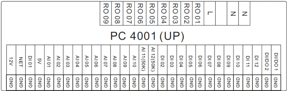
| Meaning | Meaning | ||||
1 | AC-L | Live line | 22 | DI 08 | Electric heater overload protection input |
2 | AN-N | Null line | 23 | DI 09 | COMP 1 overload protection switch input |
3 | RO 01 | Compressor 1 output (220VAC) | 24 | DI 10 | COMP 2 overload protection switch input |
4 | RO 02 | Compressor 2 output (220VAC) | 25 | DI 11 | system protection input |
5 | RO 03 | FM High speed output (220VAC) | 26 | DI 12 | Emergency switch input |
6 | RO 04 | FM low speed output (220VAC) | 27 | AI 01 | Water input temperature input |
7 | RO 05 | Water pump output (220VAC) | 28 | AI 02 | Water output temperature input |
8 | RO 06 | 4-way valve output (220VAC) | 29 | AI 03 | System 1 coil temperature input |
9 | RO 07 | Electric heater output (220VAC) | 30 | AI 04 | System 2 coil temperature input |
10 | RO 08 | Spray valve output (220VAC) | 31 | AI 05 | Ambient temperature input |
11 | RO 09 | Alarm/anti-freezing heater output (220VAC) | 32 | AI 06 | System 1 antifreeze temperature input |
12 | DI/DO 1 | Mode indicator output | 33 | AI 07 | System 2 antifreeze temperature input |
13 | DI/ DO 2 | Flow volume input | 34 | AI 08 | System 1 suction temperature input |
14 | DI 01 | Emergency switch input | 35 | AI 09 | System 2 suction temperature input |
15 | DI 02 | System 1. High pressure protection input | 36 | AI 10 | No Use |
16 | DI 03 | System 1. Low pressure protection input | 37 | AI 11 (50K) | System 1 exhaust temperature input |
17 | DI 04 | System 2. High pressure protection input | 38 | AI 12 (50K) | System 2 exhaust temperature input |
18 | DI 05 | System 2. Low pressure protection input | 39 | CN1 | System 2 electric expansion valve output |
19 | NET GND 12V | Connect to the remote controller | 40 | CN6 | System 1 electric expansion valve output |
20 | DI 06 | Phase sequence protection/input | 41 | CN4 | Program download port |
21 | DI 07 | Water flow switch protection input | 42 | CN5 | RS485 port |
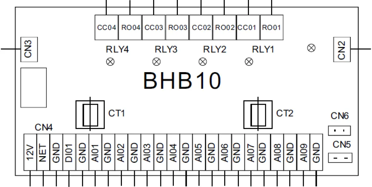
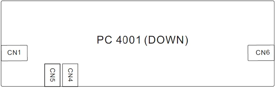
No. | Symbol | Meaning |
1 | RO01 | System 1 magnetic valve outlet (220-230VAC) |
2 | RO02 | System 2 magnetic valve outlet (220-230VAC) |
3 | RO03 | System 1 alert outlet (220-230VAC) |
4 | RO04 | System 2 alert outlet (220-230VAC) |
5 | CC01 | System 1 magnetic valve inlet (220-230VAC) |
| 6 | CC02 | System 2 magnetic valve inlet (220-230VAC) |
7 | CC03 | System 1 alert inlet (220-230VAC) |
| 8 | CC04 | System 2 alert inlet (220-230VAC) |
9 | NET GND 12V | Wire controller |
10 | DI01 GND | Mode/communication |
11 | AI01 GND | System 1 anti-freeze temp. (input) |
12 | AI02 GND | System 2 anti-freeze temp. (input) |
13 | AI03 GND | System 1 economizer inlet temp. failure (input) |
14 | AI04 GND | System 1 economizer outlet temp. failure (input) |
15 | AI05 GND | System 2 economizer inlet temp. failure (input) |
16 | AI06 GND | System 2 economizer outlet temp. failure (input) |
17 | AI07 GND | System 1 exhaust temp. (input) |
18 | AI08 GND | System 2 exhaust temp. (input) |
19 | AI09 GND | Ambient temp. (input) |
Automatic Water Filling Valve
When the automatic filled-water valve is installed, the arrowhead orientation of inlet water must accord with the orientation of the valve.
Automatic filled-water has been adjusted in advance to 1.5ba.
If readjusting the pressure of inlet water, operate as follows:
- Open the Screw Cap ( C )
- If reducing the pressure of water supply, unscrew the pressure to adjust the screw (B)
- If increasing the pressure of water supply, screw down the pressure to adjust the screw (B)
When the system needs to be filled with water at first, rest the handle (A) of filled-water. Then the handle (A) can return (close) when the system is full of water.
Automatic filled-water valve needs periodic cleaning. When you must close the tap, unscrew the plug (D), remove the inside filter net. Reassemble after cleaning.
NOTE:
There are two connections for water pressure meters in the central section of automatic filled-water, where the water pressure meter can be connected directly and display the set pressure. The screw cap ( C ) must be tweaked after adjusting the filled-water pressure.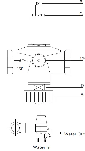
Maintenance
DO I NEED TO GET MY UNIT SERVICED?
It is recommended that you get your Evo Heat unit serviced once a year by your local certified air conditioning or refrigeration technician. If your unit is located in a coastal area, more frequent maintenance may be necessary.
During the service, they will check the operational pressures of the refrigeration system and give the unit and fins a good clean to ensure maximum performance.
DO WE HAVE RECOMMENDED SERVICE AGENTS?
Evo Heat have a large database of recommended service agents. Please contact Evo Heat tech support on 1300 859 933 for your local service agent details.
SHOULD I CHECK MY UNIT REGULARLY?
We recommend you check your unit regularly to avoid potential issues and damage to your heat pump.
- Always remember to check the water system filling equipment and air exhaust equipment in case of water interruption or air entering the system; Make sure to clean the water filter in case of blockages. The system will check the water pump every 72hrs at standby status.
- Wash the water circuit system in the unit every 6 months; Remember to check the working status of every component and check whether the working pressure is in normal range or not. If anything is abnormal, repair or replace. Remember to check the power and wire connection. If anything is abnormal, repair or replace.
- If the unit is not to be used for an extended period of time, drain the water in the water pump and water circuit from the bottom water exit so it does not freeze. If you want to start the unit again, fill water to the system and conduct a complete inspection before start-up.
- If you are not using the unit continuously, please do not turn off the power in case of spare parts freezing. Evo Heat will not take any responsibility if any damage occurs because of this mis-operation.
Warranty
- Warranty terms are from date of purchase.
- This warranty excludes any defect or injury caused by or resulting from misuse, abuse, neglect, accidental damage, improper voltage, vermin infestation, incompetent installation, any fault not attributable to faulty manufacture or parts, any modifications which affect the reliability or performance of the unit.
- This warranty does not cover the following:
- Natural Disasters (hail, lightening, flood, fire etc.)
- Rust or damage to paintwork caused by a corrosive atmosphere
- When serviced by an unauthorized person without the permission of Evo Industries
- When a unit is installed by an unqualified person
- Where a unit is incorrectly installed
- When failure occurs due to improper or faulty installation
- Failure due to improper maintenance (refer Operating Instructions)
- No Fault Found’ service calls where the perceived problem is explained within the
- Costs associated with delivery, handling, freighting, or damage to the product in transit.
- If warranty service is required you should:
- contact Evo Industries Australia on 1300 859 933 or via our Contact page on our web site
- provide a copy of your receipt as proof of purchase
- have completed the online warranty registration or provide a completed warranty card.
- Onsite technical service is available within the normal operating area of your Evo Industries authorized Service Centre. Service outside this area will incur a traveling fee.
- Unless otherwise specified to the purchaser, the benefits conferred by this express warranty and additional to all other conditions, warranties, rights and remedies expressed or implied by the Trade Practices Act 1974 and similar consumer protection provisions contained in legislation of the States and Territories and all other obligations and liabilities on the part of the manufacturer or supplier and nothing contained herein shall restrict or modify such rights, remedies, obligations or liabilities.
Warranty Registration
Evo Heat highly recommend customers to complete their warranty details online to ensure efficient warranty claim processing.
To register your warranty, scan our QR Code or head to our website and fill in the Warranty Registration Form: https://evoheat.com.au/warranty-registration/


