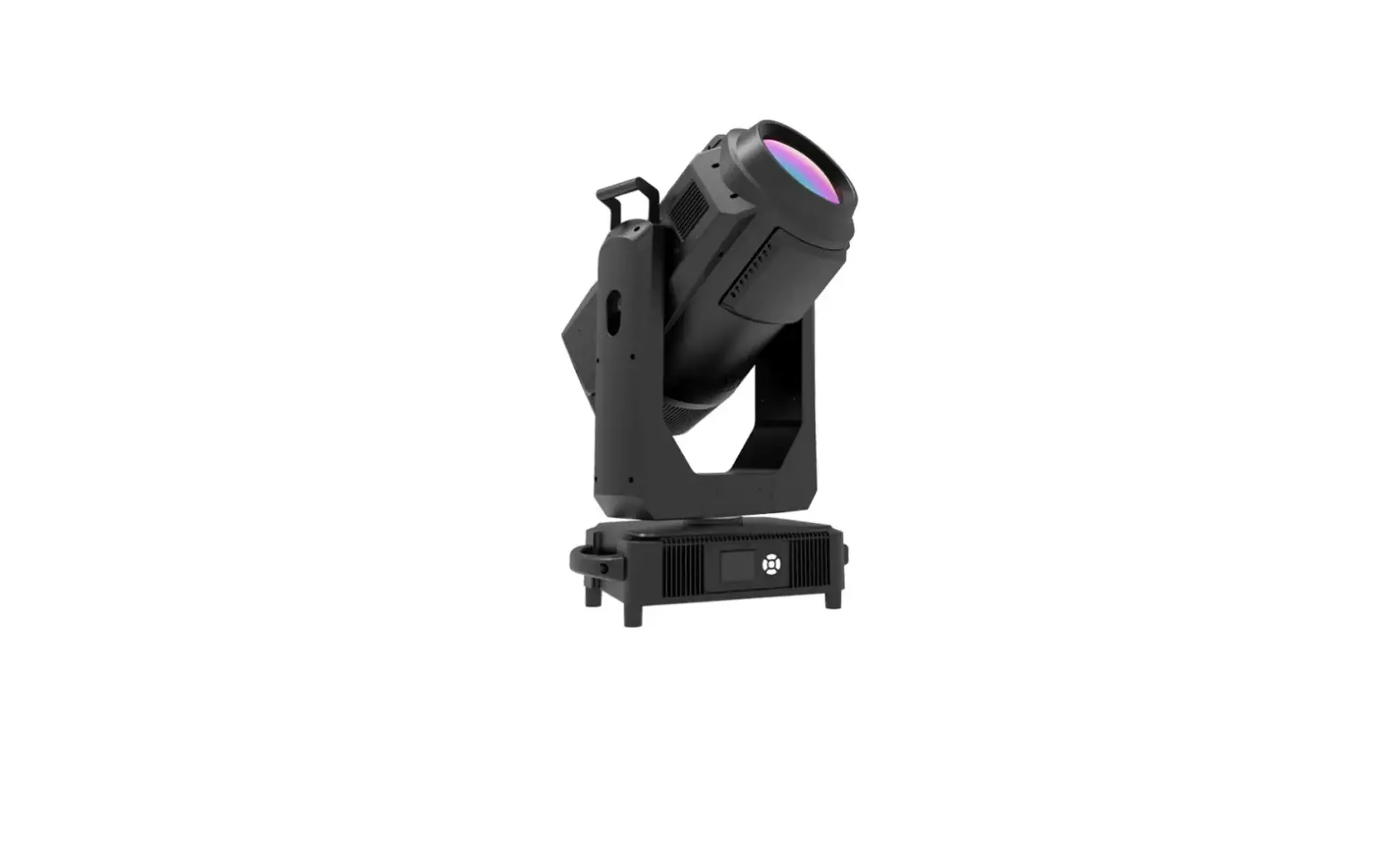
LIGHT SKY F1700WB-E Spot Light User Manual
Congratulations on choosing our company product! We thank you for your custom.
- Please note that this product, as all the others in the rich my company range, has been designed and made with total quality to ensure excellent performance and best meet your expectations and requirements.
- Carefully read this user manual in its entirety and keep it safe for future reference.
It is essential to know the information and comply with the instructions given in this manual to ensure the fitting is installed, used and serviced correctly and safely. - My company disclaims all liability for damage to the fitting or to other property or persons deriving from installation, use and maintenance that have not been carried out in conformity with this user manual, which must always accompany the fitting.
- My company reserves the right to modify the characteristics stated in this user manual at any time and without prior notice.
SAFETY INFORMATION
![]() This lighting fixture is for professional use only – it is not for household use.
This lighting fixture is for professional use only – it is not for household use.
Installation
Make sure all parts for fixing the projector are in a good state of repair. Make sure the point of anchorage is stable before positioning the projector.
The safety chain must be prgperly hooked onto the fitting and secured to the framework.
When suspending the fixture, ensure that the supporting structure and all hardware used can hold at least 10 times the weight of all the devices they support.
Mounting surface and fire protection
Please do not install the fixture onto combustible surface.
Keep all combustible materials at least 20 cm away from the fixture.![]()
Ensure a minimum clearance of 0.2m around the cooling fans and ventilation.
Do not expose the front glass to sunlight or other strong light source from any angle.
Lenses can focus the sun’s rays inside the fixture, creating a potential fire hazard.
![]()
Maximum ambient temperature
The fixture is intended for indoor application.
Do not operate the fixture if the ambient temperature (Ta) exceed 40 C
![]()
Protection against electrical shock
Connection must be made to a power supply system fitted with efficient earthing (Class I appliance according to standard EN 60598-1). It is,moreover, recommended to protect the supply lines of the projectors from indirect contact and/or shorting to earth by using appropriately sized residual current devices.


Connection to mains supply
The double insulation between the LV power supply and the control conductor on the fixture. Connection to the electricity mains must be carried out by a qualified electrical installer. Check that the mains frequency and voltage correspond to those for which the projector is designed as given on the electrical data label.
This label also gives the input power to which you need to refer to evaluate the maximum number of fittings to connect to the electricity line, in order to avoid overloading.
Don’t use the power cable when the insulation is damaged.
It must be the manufacturer or distributor or the professional person to change the damaged power cable in order to avoid any dangerous.
tc 120℃
Temperature of the external surface 120℃
The maximun temperature that can be reached on the external surface of the fitting, in a thermally steady state, is 120’C
![]()
Maintenance
Before starting any maintenance work or cleaning the projector, cut off power from the mains supply.
After switching off, do not remove any parts of the fitting, to avoid getting burnt for at least 30 minutes.
After this time the likelihood of the lamp exploding is virtually nill.
The fitting is designed to hold in any splinters produced by a lamp exploding.
The lenses must be mounted and, if visibly Damaged, they have to be replaced with genuine spares.
![]()
Lamp
The fitting mounts a high-pressure lamp that needs an external . Immediately replace the lamp if damaged or deformed by heat. The light source in this fixture shall be replaced by the manufacturer or its service agent or similar qualification. Always disconnect from mains before replacing the lamp.
![]()
Minimum distance of ilium inated objects
When the kimilaire projects an object, the minMum distance d the kminaire to the flammable object is 12 meters.
![]()
Protection against explosion
The protection screen, lens or uv screen on the lamp can be damaged to the degree of failure if visible damage, such as a crack or deep mark, should be replaced.
![]()
![]()
Protection optical radiation
Never look directly into the light source. You risk injury to your retina, which may induce blindness.
Do not look at LEDs with magnifiers, telescopes, binoculars or similar optical instruments that may concentrate the light output.

Battery
This product contains a rechargeable lead-acid battery. To preserve the environment, please dispose the battery at the end of its life according to the regulation in force.

The products referred to in this manual conform to the European Community Directives to which they are subject:
Low Voltage 2014/35/EU
Electromagnetic Compatibility 2014/30/EU
TECHNICAL INFORMATION
- Power supplies available :
- 98 264 – V~ 50/60Hz 11A
- Power :
- 2000W PF≥0.98
- Lamp:
- Light source :OSRAM lok-itHTI 1700PS
- Lamp power :1700W
- A verage life :750H
- Color T emperature :
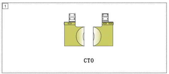
2700K-6500K,Linear CTO adjustment.
- Luminous flux output :37000LM
- Zoom Range:4°- 45°
- CRI :Ra ≥ 90
- Ballast :Electrical ballast 。
- Reflector :
- Double Reflector Cup design,German optical coating process.
- Frost :
- 1° and 20 ° can be combined.
- Dimming :
- 6 it, 0-100% linear dimming. B
- Lens :
- Diameter 200 mm large aperture optical lens set.
- Strobe :
- 9Hz synchronization, pulse, random stroboscopic.
- ControlMode :
DMX512, RDM, Art-Net,WirelessDMX512(optional). - X/Y Travel:540°/270°
- X/Y Resolution: . 2.11°/1 05°
- X/Y Speed:2.5S/1.5S
- Channel :Standard17CH
- IP set :
- built-in long-life battery, can set address without power connection.
- Software upgrade :
- Upgrade via USB interface.
- Display Menu:
- The display panel adopts a 2.8-inch color LCD screen, which is used in both Chinese and English languages to facilitate quick operation and browse menus.
- Display board can record device’s using time , show device’s temperature, channel data and software version .
- Working Mode :
- Silent , Standard, High brightness three modes.
- Features :
- Remote Control Lamp switch On/Off, automatically reduce the lamp power when the Shutter is Off.
- Temperature control :
- Intelligent temperature control, can automatically adjus the speed of the cooling fan and overheat protection.
- Error alarm :
- Automatic alarming for fixture error.
- Structure :
- plastic cover parts are made of engineering plastic PA66 + GF,with fire-proof, noise reduction, impact resistance, high temperature resistance, anti-aging characteristics.
- The vertical direction of the use of hidden locking device,convenient transportation and maintenance.
- IP RATE:IP22
- Lighting Size :503X 4X878MM 32
- Box Size :960X570X395MM
N.W. G.W. :41kg , :46kg - Flycase Size : (1PCS)
765X610X970MM
N.W.: , 41kg 85.5kg
Diagram

ATTACHMENT AND BODY SIZE
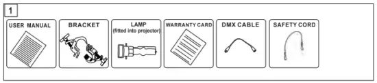
Attachment contents Fig.1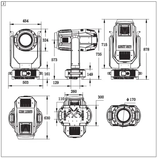
INSTALLATION AND CONNECTING
Installing the projector Fig. 3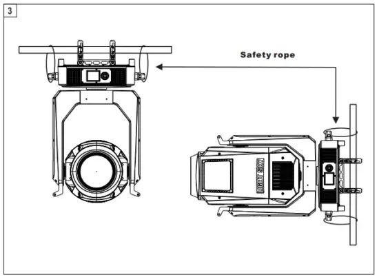
The projector can be installed on the floor resting on special rubber feet, on a truss or on the ceiling or wall.
WARNING: with the exception of when the projector is positioned on the floor, the safety rope must be fitted.
This must be securely fixed to the support structure of the projector and then connected to the base handle.
Make sure all parts for fixing the projector are in a good state of repair.
Make sure the point of anchorage is stable before positioning the projector.
When suspending the fixture, ensure that the supporting structure and all hardware used can hold at least 10 times the weight of all the devices they support.
Connecting to the mains supply fig.4
Wire color-coding and power connections:
| Conductor | Symbol | Wire Color (EU models) | Wire Color (US models) |
| live | L | brown | black |
| neutral | N | blue | white |
| ground(earth) | yellow-green | green |
- connection to the eiectricty mains must be carried out by a qualified electrical installer.
- After doing the above operation and making sure all the devices had been installed with natural operate, press the power switch to check whether every -thing is working normally.
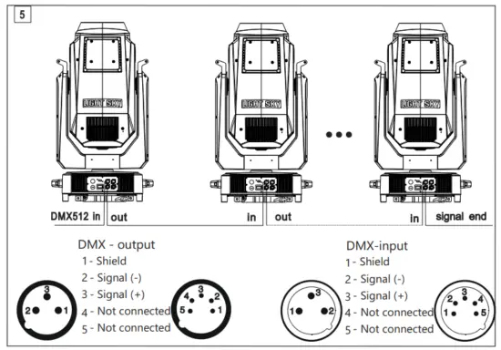
Connecting to the control signal line (DMX)- Fig.5
- Please use the round 3 or 5-pin XLR plugs &sockets offered by menu facture to connect the first projector’s output to the second projector’ input and connect the second projector’s output to the third projector’s input. And in the same way for the rest,eventually connect the last projector’s output, all the projectors are together.
- The projectors’s control signal output or input by using the 3 or 5 pin XLR pug and socket.If need to lengthen the communication cable,please make sure the both side of 3 or 5-pin plug is one to one (one to one,two to two,three to three).Otherwise, the communication cable will be interrupted.The communicate cable is 2-cord screened cable 75Ω resistance with each core is at least a 0.5mm diameter. ( Caution: All the inside leading wire of 3 or 5-pin XLR plug couldn’t touch each other or plinth).
- Recommend to use the DMX signal terminator for the installation to avoid the electronic noise dama -ge the digital control signal.Simply speaking, DMX terminator is an XLR connector with a 120Ω 1/2W resistor connected across pin 2 and 3.Which is then plugged into the output socket on the last projec -tor in the hain.Refer to the connection.
CONTROL PANEL
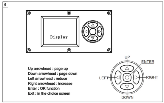
Press the switch.The projector starts resetting the effects. At the same time,the following information scrolls on the display (please refer to the actual material)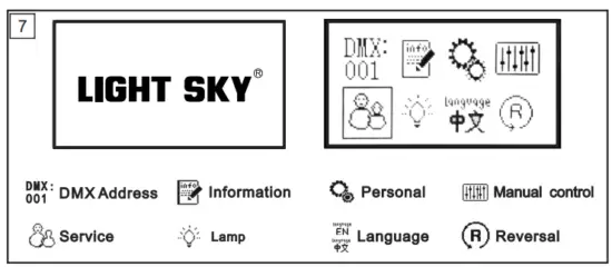
| Mainmenu | Ⅰ menu | Ⅱ menu | Ⅲ menu | ⅠV menu | ||||
| DMX SETTING | → | Address | → | 1-512 | ||||
| Channel mode | → | Standard(17) | ||||||
| Inputmode | → | DMX 512 | ||||||
| DMX State | → | Blackout | ||||||
| Hold | ||||||||
| Info |
→ | Fixture times |
→ | Power on time | 0 – 99999H | |||
| Lamp on time | 0 – 99999H | |||||||
| All time | 0 – 99999H | |||||||
| Temperatures | → | Lamp TEMP | ||||||
| Fan speed |
→ | Head fan 1 | ||||||
| Head fan 2 | ||||||||
| Lamp fan 1 | ||||||||
| Lamp fan 2 | ||||||||
| Lamp fan 3 | ||||||||
| Lamp fan 4 | ||||||||
| Power fan | ||||||||
| Fan voltage | Head fan 1 | |||||||
| Head fan 2 | ||||||||
| Lamp fan 1 | ||||||||
| Lamp fan 2 | ||||||||
| Lamp fan 3 | ||||||||
| Lamp fan 4 | ||||||||
| Power fan | ||||||||
| RDM info/RDM |
→ | UID:0x3888XXXXXXXX | ||||||
| Manufactory Label:LIGHT SKY | ||||||||
| Device Label:F1700WB-E | ||||||||
|
DMX live |
→ | 1.Pan |
→ | 0 – 255 | ||||
| 2.Pan fine | 0 – 255 | |||||||
| 3.Tilt | 0 – 255 | |||||||
| 4.Tilt Fine | 0 – 255 | |||||||
| 5.P/T speed | 0 – 255 | |||||||
| 6.Functions | 0 – 255 | |||||||
| 7.Strobe | 0 – 255 | |||||||
| 8.Dimmer | 0 – 255 | |||||||
| 9.Dimmer fine | 0 – 255 | |||||||
| 10.CTO | 0 – 255 | |||||||
| 11.Zoom | 0 – 255 | |||||||
| 12.Focus | 0 – 255 | |||||||
| 13.Focus fine | 0 – 255 | |||||||
| 14.Auto Fin. | 0 – 255 | |||||||
| 15.Auto Dis | 0 – 255 | |||||||
| 16.Frost1 | 0 – 255 | |||||||
| 17.Frost2 | 0 – 255 | |||||||
| Version info | → | Display | → | VX.XXX |
| Mainmenu | Ⅰ menu | Ⅱ menu | Ⅲ menu | ⅠV menu | ||||
| Info | → | Version info | → | Pan/Tilt |
→ | VX.XXX | ||
| Color module | VX.XXX | |||||||
| Zoom module | VX.XXX | |||||||
| FanDrv | VX.XXX | |||||||
| Ballast info | → | Input voltage | XXXV | |||||
| Output voltage | XXXV | |||||||
| Input current | XXXA | |||||||
| Output Power | XXXW | |||||||
| Internal.T | XXX℃ | |||||||
| External.T | XXX℃ | |||||||
| Running state |
→ | Error | ||||||
| OK | ||||||||
| Fault | ||||||||
| Person | → | Pan/Tilt | → | PT swap | → | OFF | ||
| ON | ||||||||
| Pan invert | OFF | |||||||
| ON | ||||||||
| Tilt invert | OFF | |||||||
| ON | ||||||||
| Power mode |
→ | 1200W mode | ||||||
| 1400W mode | ||||||||
| 1700W mode | ||||||||
| Display | → | Language | English | |||||
| Chinese | ||||||||
| Backlight time | Always | |||||||
| Auto (30S) | ||||||||
| Intensity | 0 – 100 | |||||||
| Rotation | Normal | |||||||
| Rotate 180 | ||||||||
| Auto | ||||||||
| Manual | → | Manual Control | → | 1.Pan | 0 – 255 | |||
| 2.Pan fine | 0 – 255 | |||||||
| 3.Tilt | 0 – 255 | |||||||
| 4.Tilt Fine | 0 – 255 | |||||||
| 5.P/T speed | 0 – 255 | |||||||
| 6.Functions | 0 – 255 | |||||||
| 7.Strobe | 0 – 255 | |||||||
| 8.Dimmer | 0 – 255 | |||||||
| 9.Dimmer fine | 0 – 255 | |||||||
| 10.CTO | 0 – 255 | |||||||
| 11.Zoom | 0 – 255 | |||||||
| 12.Focus | 0 – 255 | |||||||
| 13.Focus fine | 0 – 255 | |||||||
| 14.Auto Fin. | 0 – 255 | |||||||
| 15.Auto Dis. | 0 – 255 |
| Mainmenu | Ⅰ menu | Ⅱ menu | Ⅲ menu | ⅠV menu | ||||
| Manual | → | Manual Control | → | 16.Frost1 | 0 – 255 | |||
| 17.Frost2 | 0 – 255 | |||||||
| Lamp Switch | → | OFF | ||||||
| ON | ||||||||
| Reset |
→ | Pan/Tilt reset | ||||||
| Dimmer reset | ||||||||
| Color reset | ||||||||
| Focus reset | ||||||||
| Total reset | ||||||||
| Test |
→ | Test all |
→ | Test in process | ||||
| Test pan/tilt | Test in process | |||||||
| Test effects | Test in process | |||||||
| Service | → | Fixture state |
→ | Memory IC |
→ | OK/ Reset / Error | ||
| Angle Sensor | OK/ Reset / Error | |||||||
| Pan Encodeer | OK/ Reset / Error | |||||||
| Pan Drive IC | OK/ Reset / Error | |||||||
| Tilt Encoder | OK/ Reset / Error | |||||||
| Tilt Drive IC | OK/ Reset / Error | |||||||
| Pan | OK/ Reset / Error | |||||||
| Tilt | OK/ Reset / Error | |||||||
| CTO | OK/ Reset / Error | |||||||
| Zoom | OK/ Reset / Error | |||||||
| Focus | OK/ Reset / Error | |||||||
| Adjust | → | Pan |
→ | 0 – 255 | ||||
| Tilt | 0 – 255 | |||||||
| Strobe 1 | 0 – 255 | |||||||
| Strobe 2 | 0 – 255 | |||||||
| CTO | 0 – 255 | |||||||
| Zoom | 0 – 255 | |||||||
| Focus | 0 – 255 | |||||||
| Frost 1 | 0 – 255 | |||||||
| Frost 2 | 0 – 255 | |||||||
| Factory | → | Factory Reset | Pass word | YES / NO | ||||
| Reset timers | Pass word → | Reset power on timers |
→ | YES/ NO | ||||
| Reset lamp timers | YES/ NO | |||||||
| Reset all timers | YES/ NO | |||||||
| Developer | Pass word → | Correlate lamp | ||||||
| Manual Fan Vol |
| Mainmenu | Ⅰ menu | Ⅱ menu | Ⅲ menu | ⅠV menu | ||||
| Service | → | Factory | → | Developer | Pass word → | Manual Power | ||
| Manual OR DMX | ||||||||
| Update | Pass word → | Simple update | → | Display | ||||
| Pan/Tilt / XY | ||||||||
| Color module | ||||||||
| Zoom module | ||||||||
| FANDRV | ||||||||
| ALL | ||||||||
| Whole update | → | Display | ||||||
| Pan/Tilt / XY | ||||||||
| Color module Zoom module | ||||||||
| FANDRV | ||||||||
| ALL |
CHANNEL FUNCTION
| Channel | DMX | Percentage | Function | Note |
| 1 | 0-255 | 0-100 | Pan | |
| 2 | 0-255 | 0-100 | Pan Fine | |
| 3 | 0-255 | 0-100 | Tilt | |
| 4 | 0-255 | 0-100 | Tilt fine | |
| 5 | 0-255 | 0-100 | Pan/Tilt speed | |
|
6 | 0-9 | Reserved (0=default) | ||
| 10-14 | RESET ALL | |||
| 15-19 | RESET DIMMER SHUTTER | |||
| 20-24 | RESET COLOR | |||
| 25-29 | Reserved | |||
| 30-34 | RESET PT | |||
| 35-39 | RESET ZOOM | |||
| 40-44 | LAMP ON | |||
| 45-49 | LAMP OFF | |||
| 50-54 | Always | |||
| 55-59 | Auto (30S) | |||
| 60-64 | POWER MODE 1200 | |||
| 65-69 | POWER MODE 1400 | |||
| 70-74 | POWER MODE 1700 | |||
| 75-255 | Reserved | |||
|
7 | Shutter strobe | |||
| 0 – 31 | Shutter closed | |||
| 32 – 63 | Shutter open (32=default) | |||
| 64 – 95 | Strobe-effect from slow to fast | |||
| 96 – 127 | Shutter open | |||
| 128 – 143 | Opening pulse in sequences from slow to fast | |||
| 144 – 159 | Closing pulse in sequences from fast to slow | |||
| 160 – 191 | Shutter open | |||
| 192 – 223 | Random strobe-effect from slow to fast | |||
| 224 – 255 | Shutter open | |||
| 8 | 0 – 255 | 0-100 | Dimmer | |
| 9 | 0 – 255 | 0-100 | Dimmer fine | |
| 10 | 0 – 255 | 0-100 | CTO | |
| 11 | 0 – 255 | 0-100 | Zoom | |
| 12 | 0 – 255 | 0-100 | Focus | |
| 13 | 0 – 255 | 0-100 | Focus Fine | |
| 14 | 0-255 | 0-100 | Auto Fin | |
|
15 | Auto Dis | |||
| 0 – 9 | NO function | |||
| 10 — 19 | 10M | |||
| 20 — 29 | 15M | |||
| 30 — 39 | 20M | |||
| 40 — 49 | 30M |
| Channel | DMX | Percentage | Function | Note |
| 15 | 50 — 59 | 40M | ||
| 60 — 255 | 50M | |||
|
16 | Frost 1 | |||
| 0 – 127 | Minimum atomization to maximum atomization | |||
| 128 – 159 | Slow in and fast out from slow to fast | |||
| 160 – 191 | Fast in and slow out from slow to fast | |||
| 192 – 255 | Slow in Slow out from slow to fast | |||
|
17 | Frost 2 | |||
| 0 – 127 | Minimum atomization to maximum atomization | |||
| 128 – 159 | Slow in and fast out from slow to fast | |||
| 160 – 191 | Fast in and slow out from slow to fast | |||
| 192 – 255 | Slow in Slow out from slow to fast |
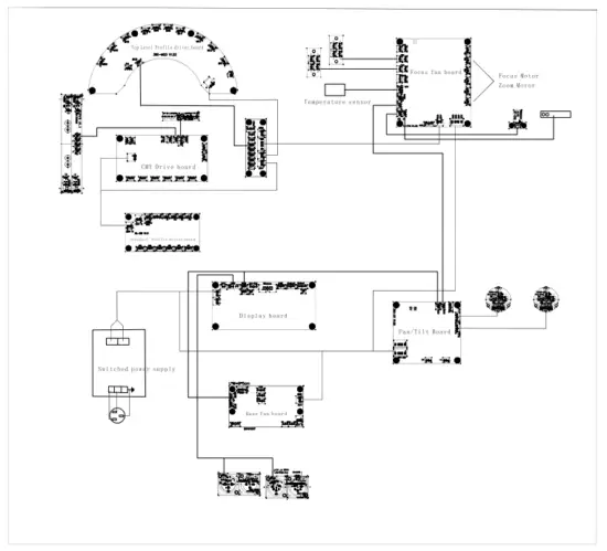
CIRCUIT CONNECTING DIAGRAM
CLEANING AND MAINTENANCE
- In order to ensure the projector could work normally. lt should be kept clean always It is recommended that the fans and ventilation in let should be cleaned every 15 days.The lens and dichroic colour filters should also be regularly cleaned to maintain an optimum light output.Do not use any type of solvent on dichroic colour filters. lt will damage the projector.
•Suggestion:The continue usage of the light don’t exceed 4 hours.Or it will shorter the usage of the lamp.Please use the alternative operation to solve this problems.
•Please disconnect the power supply when begin to maintenaceor take down the light.Please let the parts cool down 10 minute at least then begin to install. lf need to replace the lamp,please wait 10 minute again at least to let the lamp cool down completely or which maybe burned down. - Please inspect the lens or other moving parts timing and keep them clear and static. lf find anything damaged or losseness,must change a lamp or fix the lamp in order to avoid the accident.
- The light use the strong cool system. It is easy for the dirty to be collected .Please do clear the hot-sak one time two week at least.
- After you use the light,please check the intake place whether there are some wastepaper,please clean it up,or the windmill will break down and causing fire.
TROUBLESHOOTING
It is recommended some solution for some normal trouble shooting.Any unsolutioned problems should always be handle by the professional person.Disconnect the power supply before maintenance the light.
Lamp off
- Please check if install the suitable lamp.
- Please check the connection of the power supply or switch is ok.
- Please check whether the lamp will reach the end of their life can explode ,please replace a same description lamp.
- Please measure if the power supply is enough.
- Please check if the operation is correct.Please wait 30 minutes at least till the lamp cool down enough,then could the connect the power supply,which could be normal work.
- Please check whether the DMX512 controller pass the “turn on”oder.
- Please check the connection of the trigger circuit is loose contact.
- Please check whether the connected point of he trigger point is loose contact,faster the connect cable.
- Check menu “information”→fan speed/voltag→fan1,fan2,fan3” Whether the fan speed in 500RPM above,below 500RPM the lamp does not light,replace with the specifications of the fan.
- Please check if the switch of the temperature is damaged.
- Enter the menu “information”select “temperature”to see whether the temperature display boad is too high or no temperature display.
The light beam dark,not inhomogeneou.。
- when the lamp is to the usage life ,the light is not enough,please change a new one for the same description.
- Please check the reflector parts is dirty.Keep them clear.
- Please measure if the power supply is enough.
- Small adjusting is suitable for change height or screw systen till get a ideal light beam.
- Enter the menu“service options”to choose “calibration”to enter the “Color” and“Gobo” adjustment,the center can be modulated.
The light shadow is fogging。
- Please check the data on the DMX 512 controller is suitable for the electric focus.
- Please check the machenical parts is jamging. After cleaning,please add some temperature -durable juice.
The light works interruptly
- Please check if the fan works normally or mote clogging.
- Please check whether the abstract heat have the mote clogging.
- Please check if the lamp is to the usage life.
- Please check if the power supply is enough,the connection of the power supply or the circuit are good.
- Please check if the switch of the sup-temperature is good.
Though the light is Iighting, but it couldn’t accept the control order:
- Please check the start code address and the function option are correct.
- Please check whether the communicate control cable is on good connection or the cable is too long or interrupt.
- Please check the control system is not valid,check the singal amplifier of chain connected is valid.
- Please check whether the communicate cable is too long or the other equipment is mutually conjugate.
- Please arrange the wire well,Shorter the signal cable,put the high voltage cable and low voltage cable separately .
- Add the signal amplify is olator.
- Signal cable is used the excellent screening doublet (Resistance 75 Ω)
- The end of the light end and the end resistance.
- When the lamp don’t cool down enough but do the incorrect operation will let the trigger up to super- high voltage leak. lt will damage the electric circuit and communicate IC or CPU .Under this condition,please change the PCB board.
the light can’t move
- Please check if the power supply is suitable for the light voltage data.
- Please check the fuse of input voltage is defective.
- Please check the light if they are deformating,inside parts is broken,become wet…etc will lead the loose contact.
- Please check if the inside lead wire and the connector is loose.
- Please check the electric parts (such as the switch,transformer,ballast,electric capacity,piezoresistor, filter, PCB board,controller to motor) is short-circuit or burn down.
Part of the projector couldn’t be responsled to the controlling order:
- Please check the order is correct to the moving.
- Please check the mechanicalpart is deformation or loose.
- Please check the function to the motor socket is loose or drive chip is burn down. ©Please check the wire of the motor is cut at zig point.
- Please check these function to the motor is damaged.
On Working,the Pan & Tilt Couldn’t Work Normally
- Please Check According To The Above Step By Step
- Please Check The Belt Of The X.Y Is Broken
- Please Check The X/Y Direction Data To The Receiver Is Damage
- Re-Projector Reset
DUTY EXONERATIVE AND COPYRIGHT PROTECTION
- The Lamp Belongs To Consumption Products That Is Not Guarantee To Keep It In Good Repair
- Any Products Broken That Didn’t According To The Instruction Belongs To The Supplier In Final.
- No Authorize Can’t Copy
- The Information In This Manual May Be Changed In The Future,The Company Reserve The Right To Change The Data Without Any Device


