GOODWE GMK120 Smart Meter
Safety Precautions
General Disclaimer
- The information in this quick installation guide is subject to change due to product updates or other reasons. All descriptions here are for guidance only.
- Before installations, read through the quick installation guide.
- All operations should be performed by trained and knowledgeable technicians who are familiar with local standards and safety regulations.
- Check the deliverables for correct model, complete contents, and intact appearance.
- Contact the manufacturer if any damage is found or any component is missing.
- Strictly follow the installation, operation, and configuration instructions in this guide and user manual. The manufacturer shall not be liable for equipment damage or personal injury if you do not follow the instructions. For more warranty details, please visit https://en.goodwe.com/warranty.
Safety Disclaimer
 WARINING
- Make sure that the device is powered off before any operations.
- Ensure the cables are connected tightly, securely, and correctly. Inappropriate wiring may cause poor contact or damage the device.
- Additional circuit breakers are recommended on the voltage input side to avoid personal injury or device damage.
- Specification of the protective fuse should be 0.5A.
- In areas at risk of lightning, if the input cable of the device exceeds 10m (33ft), you are recommended to use an external lightning protection device. If the communication cables are wired with grounded metal conduits, the lightning protection device is not necessary.
- Strictly follow the National Electrical Code, ANSI/NFPA 70, and Canadian Electrical Code C22.1 during operations.
Check before Power-on
No. | Check Item |
1 | The product is firmly installed at a clean place that is well-ventilated and easy- to-operate. |
2 | The input power cables, CT Cables, and communication cables are connected correctly and securely. |
3 | Cable ties are intact, routed properly and evenly. |
Storage
If the equipment is not to be installed or used immediately, please ensure that the storage environment meets the following requirements:
Do not unpack the outer package or throw the desiccant away.
Store the equipment in a clean place. Make sure the temperature and humidity are appropriate and no condensation.
If the smart meter has been long term stored, it should be checked by professionals before being put into use.
Federal Communications Commission (FCC) Interference Statement
This equipment has been tested and found to comply with the limits for a Class B digital device, pursuant to Part 15 of the FCC Rules.
These limits are designed to provide reasonable protection against harmful interference in a residential installation. This equipment generate, uses and can radiate radio frequency energy and, if not installed and used in accordance with the instructions, may cause harmful interference to radio communications.
However, there is no guarantee that interference will not occur in a particular installation. If this equipment does cause harmful interference to radio or television reception, which can be determined by turning the equipment off and on, the user is encouraged to try to correct the interference by one of the following measures:
- Reorient or relocate the receiving antenna.
- Increase the separation between the equipment and receiver.
- Connect the equipment into an outlet on a circuit different from that to which the receiver is connected.
- Consult the dealer or an experienced radio/TV technician for help. This device complies with Part 15 of the FCC Rules. Operation is subject to the following two conditions:
- This device may not cause harmful interference.
- this device must accept any interference received, including interference that may cause undesired operation.
FCC Caution: Any changes or modifications not expressly approved by the party responsible for compliance could void the user’s authority to operate this equipment.
RF exposure warning
This equipment complies with FCC radiation exposure limits set forth for an uncontrolled environment.
This equipment must be installed and operated in accordance with provided instructions and the antenna(s) used for this transmitter must be installed to provide a separation distance of at least 20 cm from all persons and must not be collocated or operating in conjunction with any other antenna or transmitter.
Product Introduction
GMK120
GMK140
GM330
Waterproof box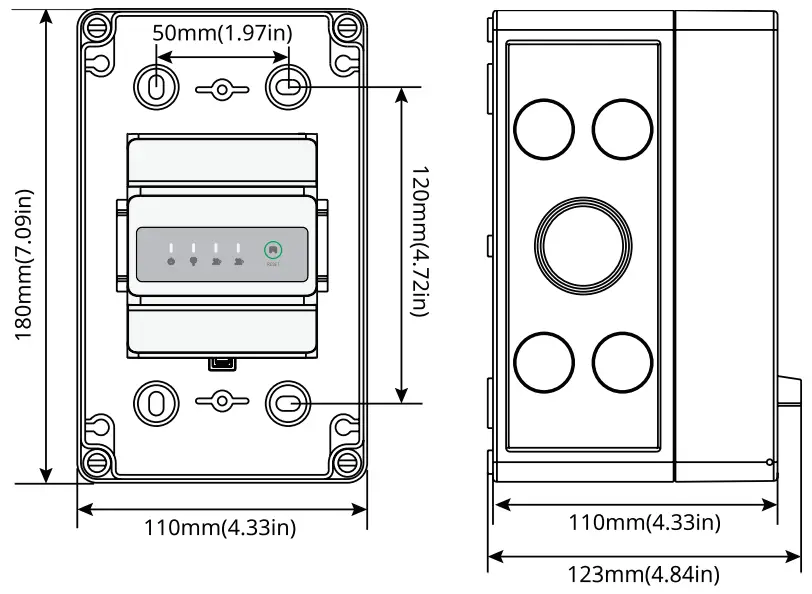
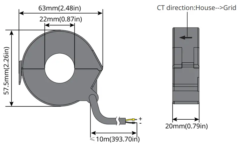
CT
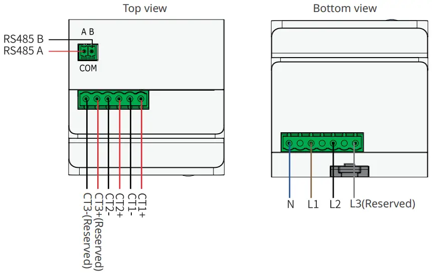
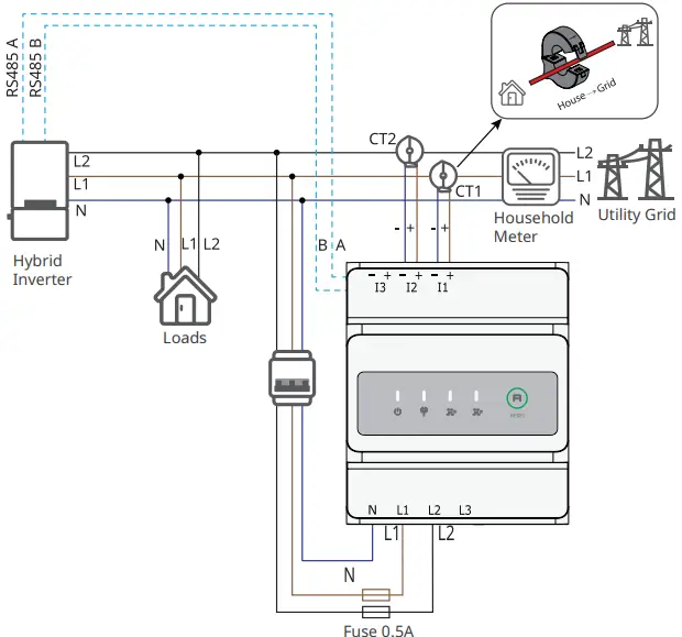
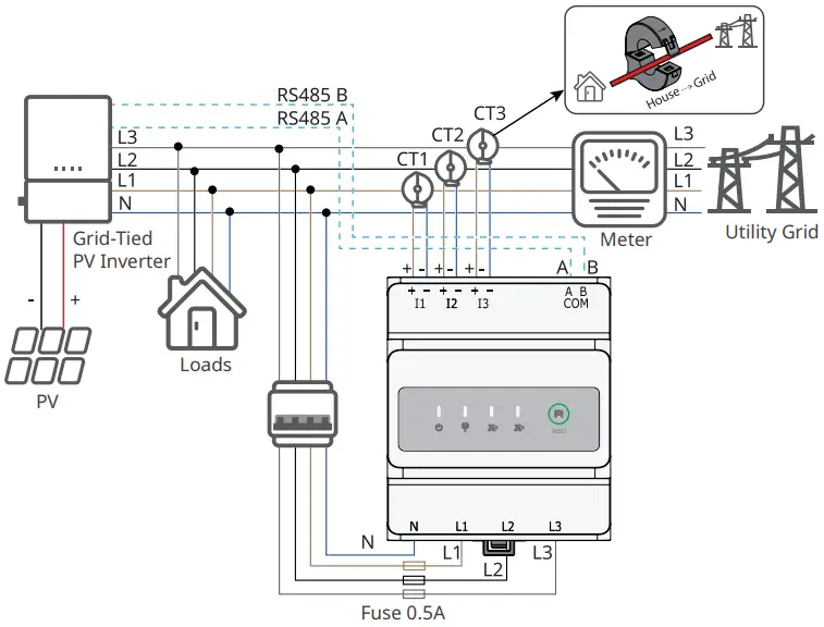
Wiring System
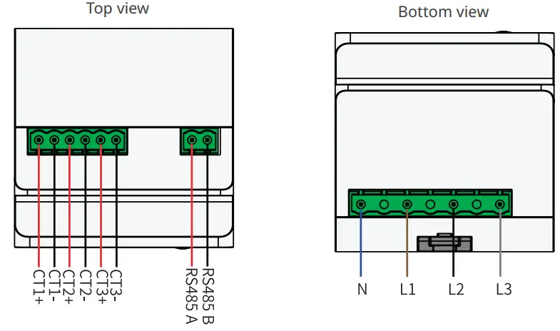
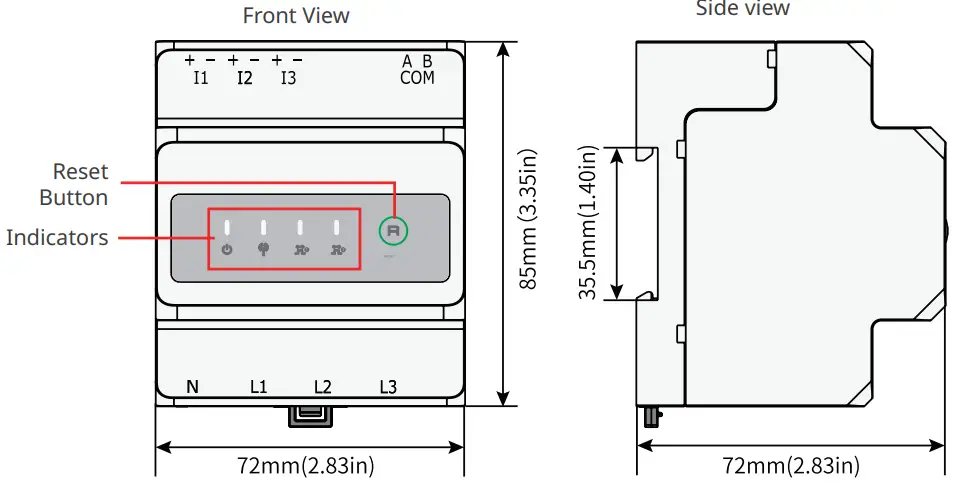
GMK120
NOTE |
|
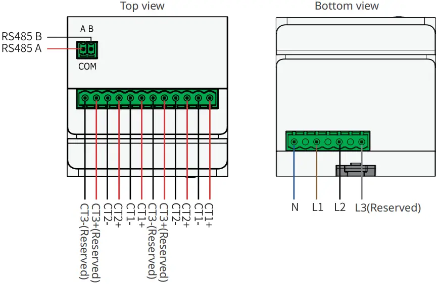
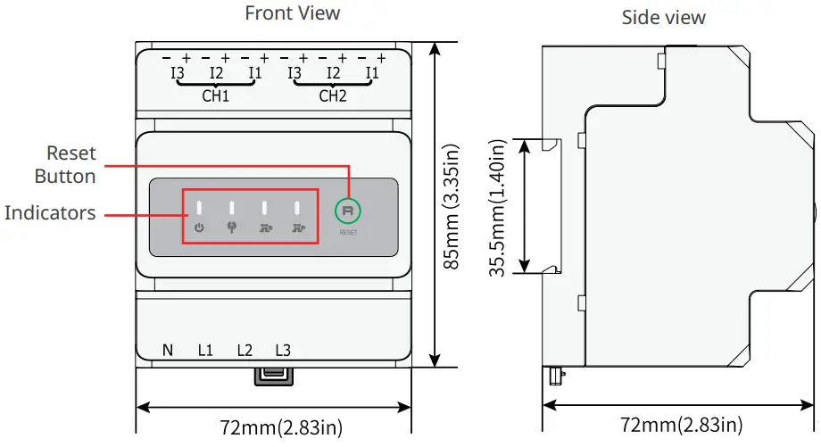
GMK140
NOTE |
|
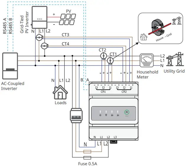
GM330
NOTE |
|
|
|


Installation
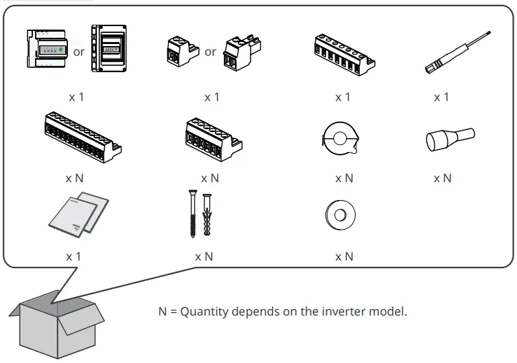
Packing List
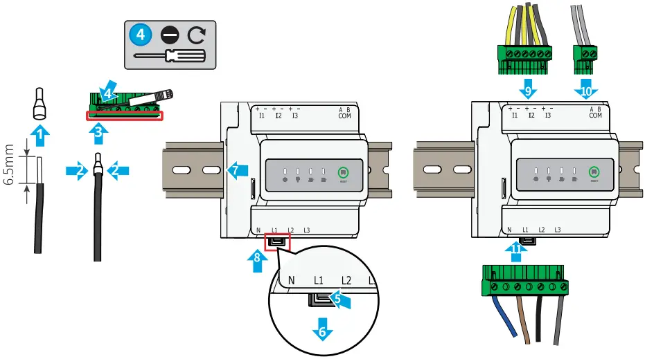
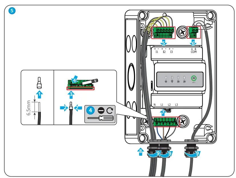
Installation and Cable Connection
|
|
NOTE |
|
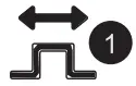
Installing the rail
Model | Tightening torque for RS485 terminals |
| GMK120 | 0.2N·m |
GMK140 | 0.2N·m |
| GM330 | 0.5N·m |
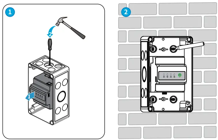
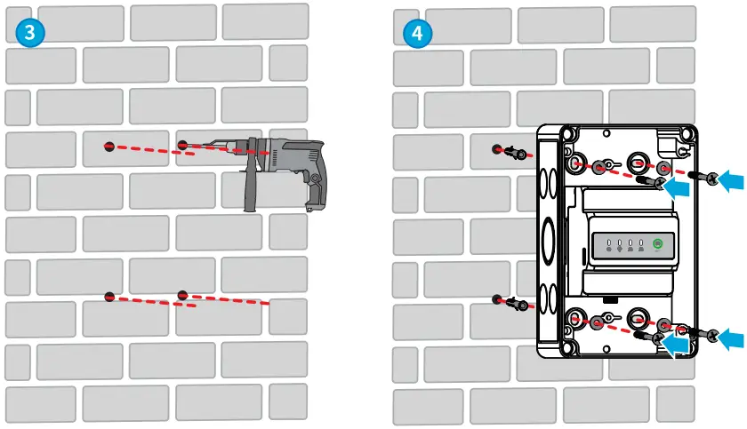
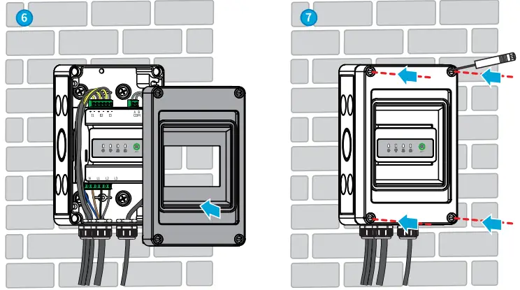
Installing the waterproof box
NOTE |
|
Commissioning
Power ON
Step 1 Connect the smart meter cables.
Step 2 Turn on the breaker on the voltage input side. Then the smart meter is powered on.
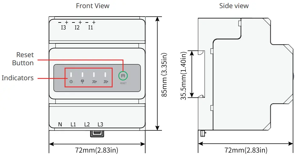
Indicator
Type | Status | Description |
| Steady on | Power on, no RS485 communication. |
| Blinking | Power on, RS485 communication works properly. | |
| Off | Power off. | |
 | Off | Reserved. |
 | Steady on | Purchasing from the utility grid. |
| Blinking | Selling to the utility grid. | |
| Off | No purchasing or selling. | |
 (Only for GMK140) | Steady on | Purchasing from the utility grid. |
| Blinking | Selling to the utility grid. | |
| Off | No purchasing or selling. |

| Press Time | Description |
| ³ 5s | Reset the smart meter. |
Maintenance
|
| Power off the smart meter before operations and maintenance. Otherwise, the smart meter may be damaged or electric shocks may occur. |
Power OFF
Turn off the breaker on the voltage input side. Then the smart meter is powered off.
|
|
Removing the Smart meter
Step1 Disconnect all the cables, including input power cable cables, CT cables, RS485 communication cables.
Step2 Press the buckle at the bottom of the device to take it from the rail.
Step3 Store the smart meter properly. If the smart meter needs to be used later, ensure that the storage conditions meet the requirements.
Technical Parameters
Model | GMK120 | GMK140 | GM330 | ||
Technical parameters | |||||
Input | Grid | Single-phase(L/N £ 265Vac) Split-phase(L/N£ 265Vac) Three-phase(3-wire,L/L£ 265Vac) Three-phase(4-wire,L/N£ 265Vac) | Three-phase(3- wire,L/L < 576Vac) Three phase(4- wire,L/N < 520Vac) | ||
| Frequency | 50/60Hz | ||||
| Voltage | Rated voltage | 208V, 120V / 240V | 277V/480V | ||
Voltage range | 0.88Un-1.1Un | ||||
Current | Rated current | 200A | 5A(MAX) | ||
| Current range | 0-200A | 0-5A | |||
Communication | RS485 interface, Modbus-RTU | ||||
| Communication Distance | RS485:1000m(Use shielded twisted-pair cables) | ||||
Display and button | 4 LED (Power supply and network communication indicator, Wireless indicator(reserved),Energy consumption indicator1,Energy consumption indicator2), Reset button | ||||
Measurement precision | Voltage/Current: 0.5 level Active energy: 0.5 level | ||||
Power supply | Power consumption £5W | ||||
| Structural parameters | Dimension (L x W x H) | 85 x 72 x 72mm/33.5×28.3×28.3in | |||
Weight | 240g/0.53lb | ||||
| Installation | Rail installation | ||||
| Environment paraments | Protection class | IP20 | |||
| Working temperature | -30℃-+70℃/-22℉-+158℉ | ||||
Storage temperature | -30℃-+70℃/-22℉-+158℉ | ||||
| Relative humidity | 0%-95%, non-condensing | ||||
Altitude | < 3000m/9842ft | ||||
NOTE |
| The smart meters are not kilowatt-hour metering devices. They can only be used to calculate the element and energy in solar and hybrid systems. Please refer to the data measured by a standard kilowatt-hour meter when you need to calculate the electricity tariff. |
Official Website
GoodWe Technologies Co., Ltd.
No. 90 Zijin Rd., New District, Suzhou, 215011, China
www.goodwe.com
[email protected]
340-00732-01
Local Contacts