![]() Meter Kit Instructions
Meter Kit Instructions
Instruction leaflet for fitting 125A Meter Pack
JK140MID
JK140MID Fitting 125A Meter Pack
Meter to be fitted when fitting incomer (see incomer instructions).
Incomer shown in place for illustration purposes.
Gently prise the DIN-rail from the support moldings.
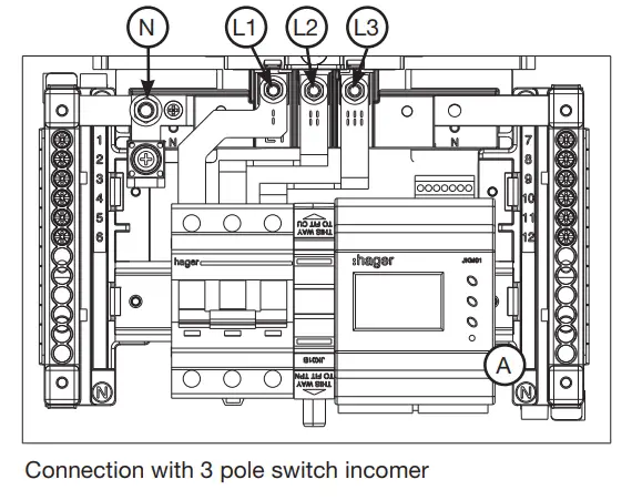
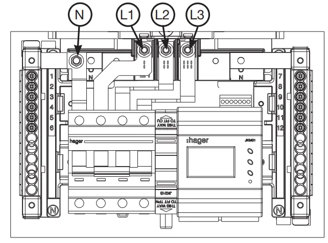
Clip the pre-wired meter to the DIN-rail (A). Ensure the cables go behind the rail. Please refer to the incomer fitting instructions for fitting of incomer links.
Clip the DIN-rail back into position. Connect the neutral link first with the M5 bolt, and then the shase links to the busbar stack, along with the loom leads (L1, L2, L3 & N)
Ensure the meter cables have sufficient clearance from the phase links.
Ensure that all electrical connections on the incomer device are tightened to 3.5Nm. Ensure the copper link upper connection points are tightened to 5Nm.
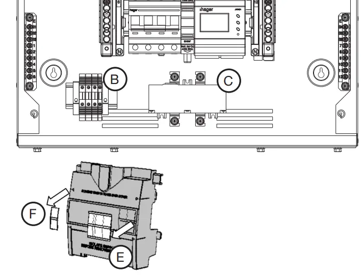
Fit the fuse rail (B) and the CT block (C) to the pre-drilled holes or using the double sided fixing tape provided.
Ensure label on front of CT reads [L1 L2 L3] when fitted.
Before fitting the shroud supplied with the meter pack kit, the device cut-out aperture needs cutting with a knife. Remove (E).
When fitting a incoming meter in a 4 – 6 way 125A TPN board it is recommended to use a JKD1125MID Meter extension box.
Hager Technical Service Centre: 01952 675 689
Hager Technical Fax: 01952 675 557
Hager Sales Service Centre: 01952 675612
Website: www.hager.co.uk
E-mail us: [email protected]
Twitter: @hageruk
ZD0893 – Issue


