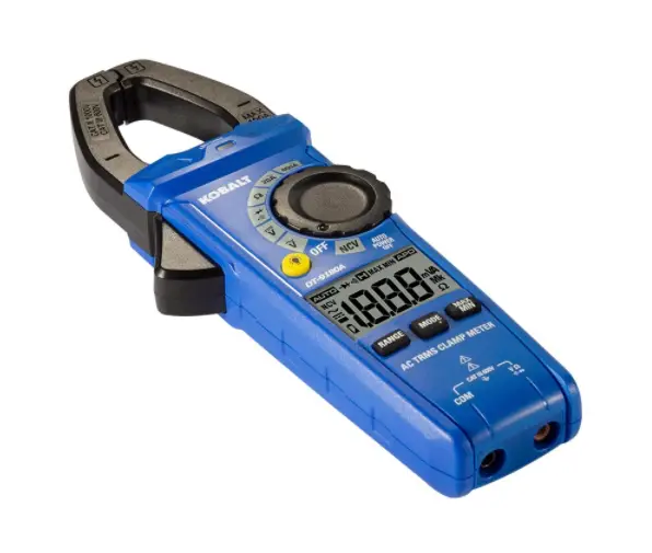
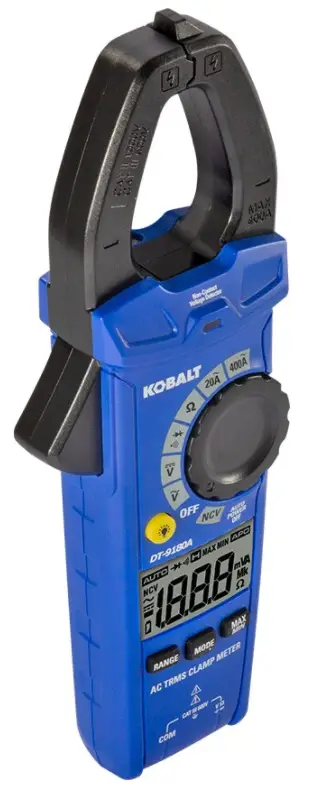
KOBALT DT-9180AKIT Clamp Meter Kit
PRODUCT SPECIFICATIONS
Input Limits
| FUNCTION | MAXIMUM INPUT |
| Voltage AC or DC | 600VAC/DC |
| Resistance, Continuity, Diode Test | 250VACIDC |
| Current AC | 400A |
Specifications
| FUNCTION | RANGE | RESOLUTION | ACCURACY |
|
AC Voltage | 2.000V | 0.001V | ±(1.2%+5 digits) |
| 20.00V | 0.01V | ||
| 200.0V | 0.1V | ||
| 600V | 1V | ||
| AllAC voltage ranges are specified from 5% of range to 100% of range. AC Voltage Bandwidth: 50 to 60Hz (All Wave); 50 to 1kHz (Sine Wave). | |||
|
DC Voltage | 200.0mV | 0.1mV | ±(0.5%+5 digits) |
| 2.000V | 0.001V | ±(0.5%+8 digits) | |
| 20.00V | 001V | ||
| 200.0V | 0.1V | ||
| 600V | 1V | ||
|
AC Current | 20.00A | 0.01A | ±(2.5%+8 digits) |
| 200.0A | 0.1A | ±(2.8%+8 digits) | |
| 400A | 1A | ||
| AllAC Current ranges are specified from 5% of range to 100% of range. Frequency Response: 50Hz to 60Hz | |||
|
Resistance | 200.0 0 | 0.10 | ±(1.2%+5 digits) |
| 2.000kO | 0.001kO | ||
| 20.00kO | 0.01kO | ||
| 200.0kO | 0.1kO | ||
| 2.000MO | 0.001MO | ±(2.0%+5 digits) | |
| 2000MO | 0.01MO | ||
Accuracy is stated at 65’F to 83’F (18’C to 28’C), less than 70% relative humidity.
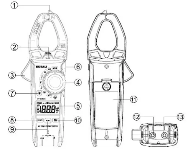
PACKAGE CONTENTS 
| PART | DESCRIPTION |
| 1 | Non-contact voltage detector |
| 2 | Non-contact voltage indicator |
| 3 | Clamp trigger |
| 4 | Rotary function switch |
| 5 | LCD display |
| 6 | HOLD and Flashlight button |
| 7 | Backlight button |
| 8 | RANGE button |
| 9 | MODE button |
| 10 | MAX/MIN button |
| 11 | Battery cover |
| 12 | COM input jack |
| 13 | V, 0, +i-, “ll input jack |
NOTE: Remove the plastic film on the LCD display before use.
Symbols
| PART | DESCRIPTION |
| & | Potential danger Indicates the user must refer to the manual for important safety information |
| & | Indicates hazardous voltages may be present. |
| [gJ | Equipment is protected by double or reinforced insulation. |
| e | This symbol advises the user that the terminal(s) so marked must not be connected to a circuit point at which the voltage with respect to earth ground exceeds (in this case) 600 VAC or VDC. |
| NCV | Non-contact AC voltage measurements |
| V | Volts |
| A | Amperes |
| 0 | Ohms |
| ~ | Alternating current/voltage |
| — | Direct current |
| . | Minus sign |
| 0 | Low battery |
| l’i.’!!ii:J | Auto ranging |
| +t | Diode test |
| • o) | Continuity |
| l:J | Display hold |
| MAX | Maximum |
| MIN | Minimum |
| Auto power off | |
| m | milli (10-3) |
| k | Kilo (103) |
| M | Mega (106) |
Safety Category Ratings
| CATEGORY RATING | BRIEF DESCRIPTION | TYPICAL APPLICATIONS |
| CATII | Single phase receptacles and connected loads | – Household appliances, power tools – Outlets more than 30ft (1Om) from a CAT 111 source – Outlets more than 60ft (20m) from a CAT IV source |
|
CATIII | Three phase circuits and single phase lighting circuits in commercial buildings | – Equipment in fixed installations such as 3-phase motors, switchgear and distribution panels – Lighting circuits in commercial buildings – Feeder lines in industrial plants – Any device or branch circuit that is close to a CAT Ill source |
The measurement category (CAT) rating and voltage rating is determined by a combination of the meter, test probes and any accessories connected to the meter and test probes. The combination rating is the LOWEST of any individual component.
Test Leads
WARNING: Operation is limited to CAT II applications when the insulated tips are removed from one or both test probes Refer to Input Limits section in this manual for Maximum voltage ratings.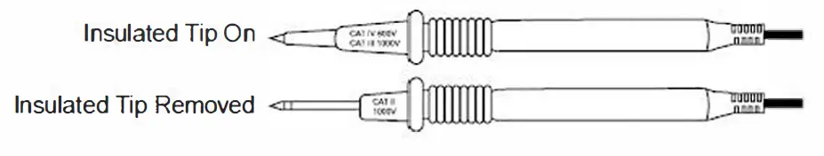
SAFETY INFORMATION
- Please read and understand this entire manual before using this product.
- Before changing functions using the rotary selector switch, always disconnect the test leads from the circuit under test.
- Ensure that the test leads are fully seated in the input jacks and keep fingers away from the metal probe tips when taking measurements.
- Use only certified test leads with the proper safety category rating.
- Verify meter’s operation by measuring a known voltage.
- Comply with all safety codes. Use approved personal protective equipment when working near live electrical circuits – particularly with regard to arc-flash potential.
- Use caution when working on or near bare conductors or bus bars.
- Use caution on live circuits. Voltages above 30V AC RMS, 42V AC peak, or 60V DC pose a shock hazard.
- Do not use the meter in wet or damp environments or during electrical storms.
- Do not use the meter near explosive vapors, dust or gasses.
- Do not use the meter if it operates incorrectly. Protection may be compromised.
- Do not operate meter while Low Battery warning is on. Replace batteries immediately.
- Do not apply voltage or current that exceeds the meter’s maximum rated input limits
OPERATING INSTRUCTIONS
RANGE Button
When the meter is first turned on, it automatically goes into Auto Ranging. This automatically selects the best range for the measurements being made and is generally the best mode for most measurements. For measurement situations requiring that a range be manually selected, perform the following:
- Press the RANGE button. The “AUTO” display indicator will turn off
- Press the RANGE button to step through the available ranges until you select the range you want.
- Press and hold the RANGE button for 2 seconds to exit the Manual Ranging mode and return to Auto Ranging.
MODE Button
Press the MODE button to select Diode Test, Continuity.
MAX/MIN Button
- Momentarily press the MAX/MIN button to activate the MAX/MIN mode. The “MAX” indicator will appear on the LCD display. The meter will display and hold the maximum reading and will update when a higher “max” occurs.
- Momentarily press the MAX/MIN button again to view the lowest reading. The “MIN” indicator meter will appear on the LCD display. The meter will display and hold the minimum reading and will update when a lower “min” occurs.
- Press and hold the MAX/MIN button to exit MAX/MIN and return to normal operation.
NOTE: The meter does not auto range when the MAX/MIN mode is active, the display will read “OL” if the range is exceeded. When this occurs, exit MAX/MIN and use the RANGE button to select a high range.
Backlight Button
- Press the Backlight button to turn on or off the backlight.
HOLD and Flashlight Button
- The hold function freezes the reading in the display. Press the HOLD and Flashlight button momentarily to activate or to exit the HOLD function.
- Press the HOLD and Flashlight butt-on for >2 second to turn on or off the flashlight function.
Auto Power Off
- To extend battery life, the meter will automatically turn off in 15 minutes if there is no operation. To disable the auto power off feature, hold down the MODE button and turn the meter on.
Low Battery Indication
- The C icon will appear on the left corner of the display when the battery voltage becomes low. Replace the battery when C icon appears.
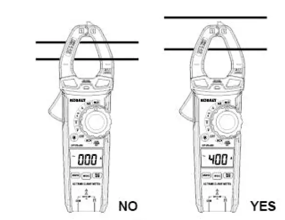
AC Current Measurements
WARNING: Disconnect the test leads and temperature probe from the meter before making current clamp measurements. Do not measure current on conductors that are more than 600V above earth ground. Observe all safety precautions when working on live conductors.
- Set the rotary function switch to the 400A or 20A AC position.
- If the range of the measured is unknown, select the higher range first then move to the lower range if necessary.
- Press the trigger to open the jaw. Clamp around a single conductor making sure the jaws are fully closed before taking a measurement. For best results, center the conductor inside the jaw.
- Read the current on the LCD display.

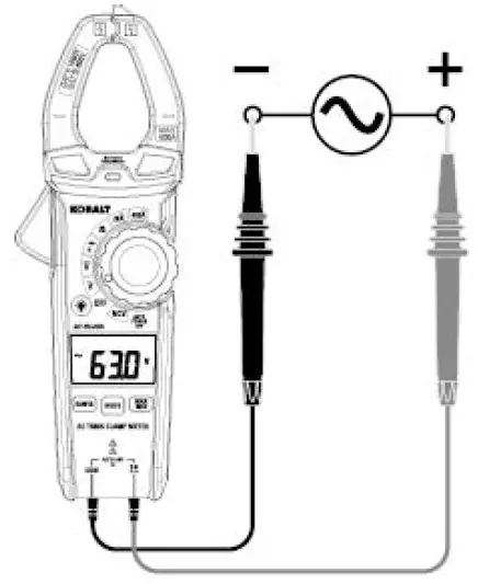
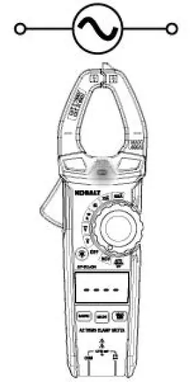
AC Voltage Measurements
WARNING: Observe all safety precautions when working on live voltages.
- Set the roatray function switch to the v position.
- Insert the black test lead banana plug into the COM input jack.
- Insert the red test lead banana plug into the V n •$ +. input jack.
- Connect the test leads in parallel to the circuit under test.
- Read the voltage on the LCD display.

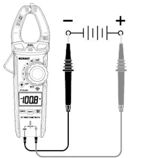
DC Voltage Measurements
WARNING: Observe all safety precautions when working on live voltages.
- Set the rotary function switch to the position.
- Insert the black test lead banana plug into the COM input jack.
- Insert the red test lead banana plug into the V n •$ +. input jack.
- Connect the test leads in parallel to the circuit under test.
- Read the voltage on the LCD display.

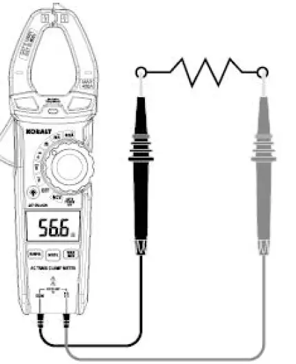
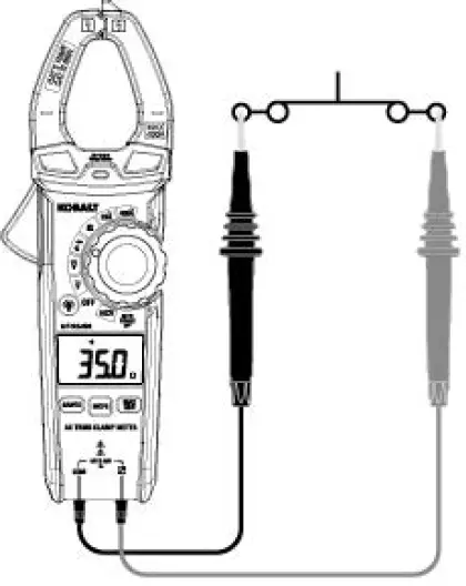
Resistance Measurements
WARNING: Never test resistance on a live circuit.
- Set the rotary function switch to the n position.
- Insert the black test lead into the COM input jack.
- Insert the red test lead into the V n •$ -+I input jack.
- Touch the test probe tips across the circuit or component under test. It is best to disconnect one side of the device under test so the rest of the circuit will not interfere with the resistance reading.
- Read the resistance on the LCD display.

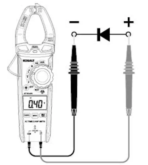
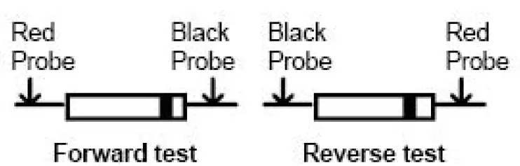
Diode Test
WARNING: Never test diodes in a live circuit.
- Set the rotary function switch to the -M-•$ position.
- Insert the black test lead into the COM input jack.
- Insert the red test lead into the V n •$ -+I input jack.
- Press the MODE button until the “-+1-” symbol appears on the LCD display.
- Touch the test lead probes to the diode under test.
- Forward voltage will indicate 0.4V to 0.7V on the LCD display. Reverse voltage will indicate “OL”. Shorted devices will indicate near OV and an open device will indicate “OL” in both polarities.


Continuity Test
WARNING: Never test continuity on a live circuit.
- Set the rotary function switch to the •• position.
- Insert the black test lead into the COM input jack. and insert the red test lead into * the V n ·$ input jack.
- Press the MODE button until the “◄” symbol appeais on the LCD display.
- Touch the test lead probes to the device or wire under test.
- A beeper will sound if the resistance is approx. 50 ohms or less and the resistance reading will be shown on the LCD display.

Non-contact AC Voltage Detector (100V to 600V)
WARNING: Risk of Electrocution. Before use, always test the Voltage Detector on a known live circuit to verify proper operation.
- Set the rotary function switch to the NCV position and the “NC\/” symbol appeais on the LCD display.
- Hold the detector close to the AC voltage being tested.
- If no voltage field is detected, the LCD will show “EF”, NCV indicator light will not flash and there will be no beeper sound.
- According to the detected voltage field, the LCD will display different horizontal lines. When the voltage field is strongest, LCD displays three horizontal lines, when the voltage field is weakest, only one line. At the same time, the NCV indicator light flashes, the beeper will make a different sound.

NOTE:
- The conductors in electrical cord sets are often twisted. For best results, rub the probe tip along a length of the cord to assure placing the tip in close proximity to the live conductor.
- The detector is designed with high sensitivity. Static electricity or other sources of energy may randomly trip the sensor. This is normal operation.
- Insulation type and thickness, distance from the voltage source, shielded wires, and other factors may affect reliable operation. Use other methods to verify live voltage, if there is any uncertainty.
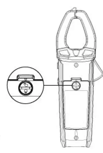
Battery Replacement
WARNINGS: To avoid electric shock, disconnect the test leads from any source of voltage before removing the battery cover. DO NOT operate this meter until the battery cover has been properly secured.
- Use small coin to unlock battery door.
- Lift up on tab below lock to remove battery door.
- Replace battery with three AAA 1.5V batteries.
- Install the battery cover and lock the battery cover securely
WARNINGS: To avoid electric shock, do not operate your meter until the battery covers is in place and fastened securely.
CARE AND MAINTENANCE
- Keep the meter dry. If it gets wet, wipe it off.
- Keep the meter clean. Wipe the dirt with a soft cloth dampened with water. Do not use chemicals, cleaning solvents, or detergents.
- Use and store the meter in normal temperatures. Temperature extremes can shorten the life of the electronic parts and distort or melt plastic parts.
- Handle the meter gently and carefully. Dropping it can damage the electronic parts or the case.
- Use only fresh batteries of the recommended size and type. Batteries are to be inserted with the correct polarity. Remove old or weak batteries so they do not leak and damage the unit.
- Do not mix old and new batteries. Do not mix different types of batteries such as alkaline, carbon-zinc, or rechargeable batteries. Non-rechargeable batteries are not to be recharged.
- If the meter is to be stored for a long period of time, the batteries should be removed to prevent damage to the unit.
TROUBLESHOOTING
| PROBLEM | POSSIBLE CAUSE | CORRECTIVE ACTION |
|
No reading on the LCD display | 1.Batteries are weak 2.Batteries are not correctly installed 3.Rusty battery pole piece 4.The LCDI meter is damaged | 1. Replace batteries 2. lnstall batteries observing polarity shown inside battery compartment 3. Wipe the battery pole piece 4. Replace meter |
| Current range measures normal, but voltage/resistance measure abnormal | 1.Test leads are broken 2.lnput stud loose 3.Low battery symbol shows on LCD display | 1.Replace test leads 2.Strengthen the input stud contact 3.Replace batteries |
| Voltage/resistance measures normal, but current measure abnormal | Poor jaw contact | Make sure the jaws are fully closed |
| Abnormal noise appears inside the device | Loose parts | Open the back cover to check and clean up |
AC Current Line Splitter
PRODUCT SPECIFICATIONS
| GEMERAL SPECIFICATIONS | |
| Voltage Rating | 125V AC maximum |
| Current | 15AAC maximum |
| Operation Environment | 32°F to 104°F(0°C to 40°C) at <70% relative humidity |
| Storage Environment | 14°F to 122 °F{-10°C to 50°C) at <80% relative humidity |
| Operating Altitude | 7000ft (2000m) maximum |
| Net Weight | Approx.0.25Ib (114g) |
| Dimensions | Approx.4.3×2.4×1.7in (110x60x42mm) |
| Safety | Conforms to UL STD. 61010-1 for measurement CAT Ill 300V, Polution Degree 2 |
PACKAGE CONTENTS
| PART | DESCRIPTION |
| 1 | Three-pin plug |
| 2 | Test circle |
| 3 | Test socket |
SAFETY INFORMATION
WARNINGS:
- Please read and understand this entire manual before using this product.
- The tester’s safety features may not protect the user if not used in accordance with the manufacturer’s instructions.
- For use on standard US and Canadian 120 volt AC outlets only.
- 15 amps AC maximum. Do not test electrical devices that exceed 15 amps.
Symbols
| PART | DESCRIPTION |
| & | Potential danger. Indicates the user must refer to the manual for important safety information |
| & | Indicates hazardous voltages may be present. |
| [g] | Equipment is protected by double or reinforced insulation. |
Safety Category Ratings
| CATEGORY RATING | BRIEF DESCRIPTION | TYPICAL APPLICATIONS |
|
CATII | Single phase receptacles and connected loads | – Household appliances, power tools – Outlets more than 30ft (10m) from a CAT Ill source – Outlets more than 60ft (20m) from a CAT IV source |
|
CATIII | Three phase circuits and single phase lighting circuits in commercial buildings | – Equipment in fixed installations such as 3-phase motors, switchgear and distribution panels – Lighting circuits in commercial buildings – Feeder lines in industrial plants -Any device or branch circuit that is close to a CAT 111 source |
The measurement category (CAT) ratiing and voltage rating is determined by a combination of the meter, test probes and any accessories connected to the meter and test probesThe combination rating is the LOWEST of any individual component.
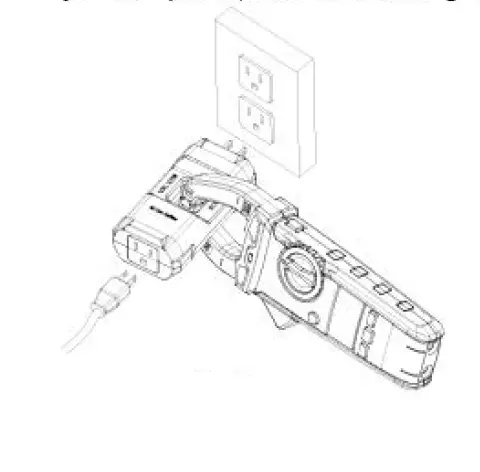
OPERATING INSTRUCTIONS
WARNINGS
For use on 120 volt AC outlets only.
- Plug the appliance or electrical device being tested into the line splitter. The splitter will work with a 2-wire or 3-wire power cord.
- Plug the line splitter into an AC outlet.
- Tum on the appliance or electrical device being tested.
- Refer to clamp meter manual for instructions on how to measure AC current.
- Clamp the jaws of the clamp meter around the square opening of the line splitter. Make sure the jaws are fully closed before taking a reading.
- Divide the current reading shown on the damp meter display by 10. For example, if the clamp meter displays 10 amps AC, the actual reading is 1 amp AC.

CARE AND MAINTENANCE
- Keep the tester dry. If it gets wet, wipe it off.
- Keep the tester clean. Wipe the dirt with a soft cloth dampened with water. Do not use chemicals, cleaning solvents, or detergents.
- Handle the meter gently and carefully. Dropping it can damage the electronic parts or the case.
- Use and store the tester in normal temperatures. Temperature extremes can shorten the life of the electronic parts and distort or melt plastic parts.
Receptacle Tester – W/GFCI
PRODUCT SPECIFICATIONS
| GENERAL SPECIFICATIONS | |
| Measure Voltage | 125VAC maximum |
| Operating Environment | 32°F to 104°F (0°C to 40°C) at <80% relative humidity |
| Storage Environment | 14°F to 140°F (-10°C to 60°C) at <80% relative humidity |
| Operating Altitude | 7000ft (2000m) maximum |
| Net Weight | Approx.0.1Ib (47g) |
| Dimension | Approx.1.3×1.7×3.8in (34x44x96mm) |
| Safety | Co lies with UL 1436 for measurement Category 11 125 , Pollution Degree 2 |
PACKAGE CONTENTS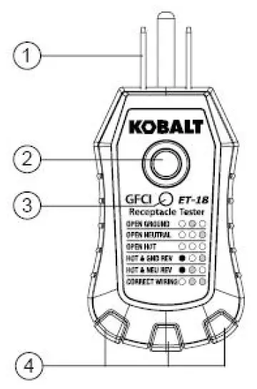
| PART | DESCRIPTION |
| 1 | Three-pin pluq |
| 2 | GFCI test button |
| 3 | GFCI LED indicator |
| 4 | Neon indicators |
Symbols
| PART | DESCRIPTION |
| & | Potential danger. Indicates the user must refer to the manual for important safety information. |
| & | Indicates hazardous voltages may be present. |
| [g) | Equipment is protected by double or reinforced insulation. |
Safety Category Ratings
The measurement category (CAT) rating and voltage rating is determined by a combination of the meter,test probes and any accessories connected to the meter and test probes. The combination rating is the LOWEST of any individual component.
SAFETY INFORMATION
WARNINGS:
- The protection provided by the tester may be impaired if used in a manner not specified by the manufacturer.
- Refer to the instruction manual for proper use. Incorrect use may result in damage to the device or its components.
- For use on 110-120VAC receptacles only.
- All appliances or equipment on the circuit being tested should be unplugged to help avoid erroneous readings.
- This tester is not a comprehensive diagnostic instrument. It will not:
- Indicate quality of the ground.
- Detect 2 hot wires in a circuit.
- Detect a combination of defects.
- Indicate reversal of grounded and grounding conductors.
- Refer all indicated problems to a qualified electrician.
OPERATING INSTRUCTIONS
Receptacle Wiring Test Instructions
WARNING: For use on 120 volt AC receptacles only.
- Before performing test, verify operation on a known good receptacle that is properly wired and live.
- Plug the tester into the receptacle being tested.
- Compare lit Neon lights to the diagnostic chart printed on the tester.
- If the tester does not indicate a properly wired outlet, consult a qualified electrician.
Diagnostic Chart
| NEON INDICATOR | FAULT | REASON FOR WIRING FAULT |
| 0 • 0• | Open Ground | Ground contact is not connected |
| 0 0 | Open Neutral | Neutral contact is not connected |
| 0 0 () | Open Hot | Hot contact is not connected |
| • 0 0 | Reversed Hot/ Ground | Hot and ground connections are interchanged |
| • • 0 | Reversed Hot/ Neutral | Hot and neutral connections are interchanged |
| 0 | Correct | Receptacle is wired correctly |
GFCI Test Instructions
WARNING: For use on 120 volt AC receptacles only.
- Check the instructions on the specific GFCI device you are testing before proceeding.
- Check to make sure the receptacle is properly wired before proceeding with the GFCI test Refer lo Receptacle Wiring Test Instructions.
- Press the test button on the GFCI receptacle. The GFCI should trip. If not, do not use the receptacle and consult a qualified electrician. If it does trip, press the reset button on the GFCI receptacle.
- Insert the tester into the receptacle being tested.
- Press the GFCI button on the tester. The GFCI should trip and the indicator lights on the tester should turn off.
- If the GFCI does not trip, either the receptacle is miswired or the GFCI is defective. Do not use the receptacle and consult a qualified electrician.
CAUTION: When testing a GFCI installed on a 2-wire (non-grounded) outlets, the tester may indicate a faulty GFCI. If this occurs, press the test button on the GFCI receptacle. The GFCI should trip. Restore power by pressing the GFCI reset button.
CARE AND MAINTENANCE
- Keep the tester dry If it gets wet, wipe it off.
- Keep the tester clean. Wipe the dirt with a soft cloth dampened with water. Do not use chemicals, cleaning solvents, or detergents.
- Handle the tester gently and carefully. Dropping it can damage the electronic parts or the case.
- Use and store the tester in normal temperatures. Temperature extremes can shorten the life of the electronic parts and distort or melt plastic parts.
TROUBLESHOOTING
| PROBLEM | POSSIBLE CAUSE | CORRECTIVE ACTION |
| GFCI no working | Test socket does not match | Switch to 6mA GFCIbutton for test |
| Neon lights no indication | Neon light damaged | Replace tester |
Users of this product are cautioned not to make modifications or changes. Doing so may void the compliance of this product with applicable laws and regulatory requirements and may result in the loss of the user’s authority to operate the equipment. “This device complies with part 15 of the FCC Rules. Operation is subject to the following two conditions: (1) This device may not cause harmful interference, and (2) this device must accept any interference received, including interference that may cause undesired operation.”
Lowe’s Home Centers LLC
1000 Lowe’s Blvd.
Mooresville, NC 28117
1-888-3KOBAL T (1-888-356-2258)
This equipment has been tested and found to comply with the limits for a Class B digital device, pursuant to part 15 of the FCC Rules. These limits are designed to provide reasonable protection against harmful interference in a residential installation. This equipment generates, uses and can radiate radio frequency energy and, if not installed and used in accordance with the instructions, may cause harmful interference to radio communications. However, there is no guarantee that interference will not occur in a particular installation. If this equipment does causeharmful interference to radio or television reception, which can be determined by turning the equipment off and on, the user is encouraged to try to correct the interference by one or more of the following measures:
- Reorient or relocate the receiving antenna.
- Increase the separation between the equipment and receiver.
- Connect the equipment into an outlet on a circuit different from that to which the receiver is connected.
- Consult the dealer or an experienced radiofTV technician for help.
CAUTION: Changes or modifications not expressly approved by the party responsible for compliance could void the user’s authority to operate the equipment.”
WARRANTY: Three-year warranty. Incidental or consequential damages are excluded from this warranty.


