![]()
C126
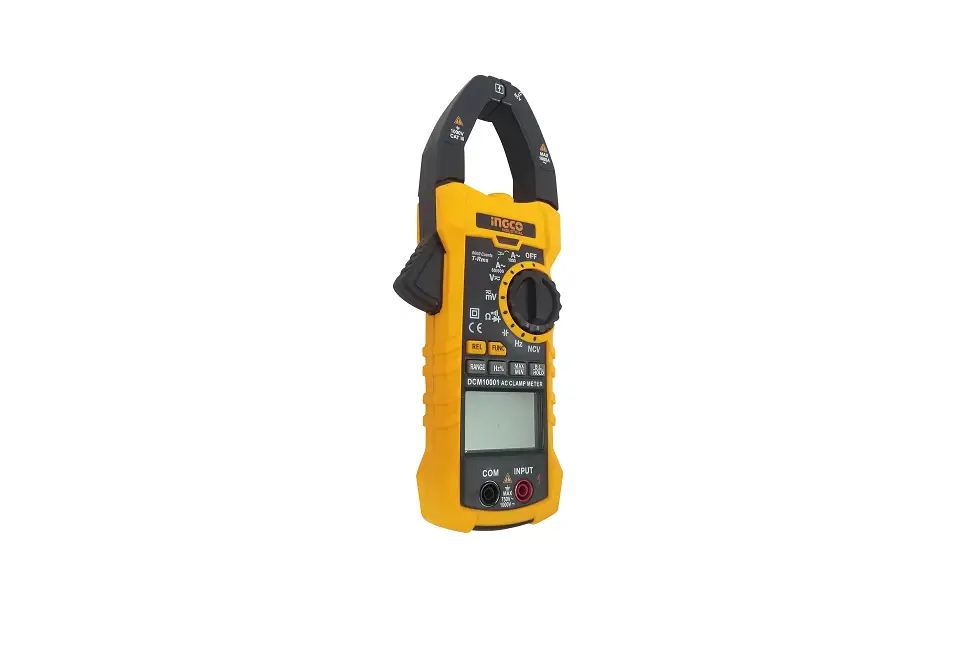
Digital 1000A AC
Clamp Meter
C128
Digital 1000A AC/DC
Clamp Meter
User Manual
REGISTER YOUR PRODUCT
www.uniks.it
The registration of your products will allow you to stay informed about news, take advantage of advantageous discounts dedicated to you for the purchase of accessories and products for your daily work.
Registration is free
1. Safety Information
![]() WARNING
WARNING
Special attention shall be paid when using the meter, improper use might cause an electric shock or damage the meter. General safety procedures shall be followed during the use and safety measures regulated by the instruction manual shall be completely respected.
To fully make use of the functions of the meter and ensure safe operation, please carefully read and follow the use method of this manual.
Instrument complies with safety requirements on electronic measuring instrument of EN-61010-1, EN-61010-2-030 and EN-61010-2-032, level II pollution, and over-voltage standard is CAT III 1000V , CAT IV 600V. The C126 model only measures AC current while the C128 model measures AC / DC current.
Please observe safety operation guide, and guarantee to use instrument in a safe manner.
1.1 Preparation
1.1.1 When use the meter, users must comply with the standard safety rules:
– General protection against electric shock
– Prevent misuse of the meter
1.1.2 After received the meter, check if it has been damaged during the delivery.
1.1.3 After been kept and delivered in shoddy conditions, check and confirm if the meter is damaged or not.
1.1.4 The pen-shape meter must be in good condition. Before use, check the pen-shape meter see if any damage to the insulation, if the metal wire of the cable is bare
1.2 Symbol
![]() Note (important security information, see the Instruction Manual)
Note (important security information, see the Instruction Manual)![]() Able to be used on dangerous electrified conductors.
Able to be used on dangerous electrified conductors.![]() Dual- insulation protection (Category II).
Dual- insulation protection (Category II).
CAT III ,CAT IV follows the over-voltage (Setup) level III and of IEC-61010-1 standard and pollution degree 2 means the impulse withstand voltage level of protection provided.![]() In line with the European Union (EU) Standard
In line with the European Union (EU) Standard![]() Grounded
Grounded
1.3 Maintenance
1.3.1 Please do not attempt to open the bottom case to adjust or repair the meter, such operation could only be performed by technicians fully aware of the meter and the risk of electric shock
1.3.2 Before opening the meter case or battery cover at the end, the pen-shape meter should be removed from the circuit being measured.
1.3.3 o avoid electric shock that might be caused by erroneous readings, when the meter displays “![]() ” symbol, the battery should be replaced immediately.
” symbol, the battery should be replaced immediately.
1.3.4 Use a damp cloth and mild detergent to clean the meter, do not use abrasive cleaning agents or solvents
1.3.5 Power supply of the meter should be turned off when not in use, range switch to the OFF position.
1.3.6 If the meter is not used for a long time, batteries should be removed to prevent damage to the meter.
2. Description
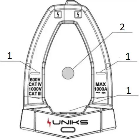
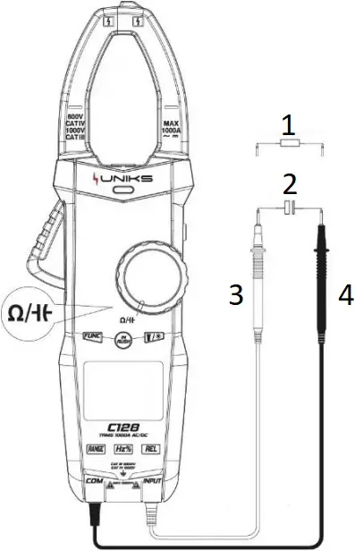
2.1 Part Name
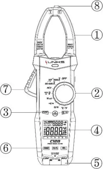
1 Current clamp head: used for measuring current
2 Rotary switch
3 Function/InRush/backlight
4 Display screen 5 Input socket
6 Function button 7 Trigger
8 Non-contact voltage detecting & inducing area
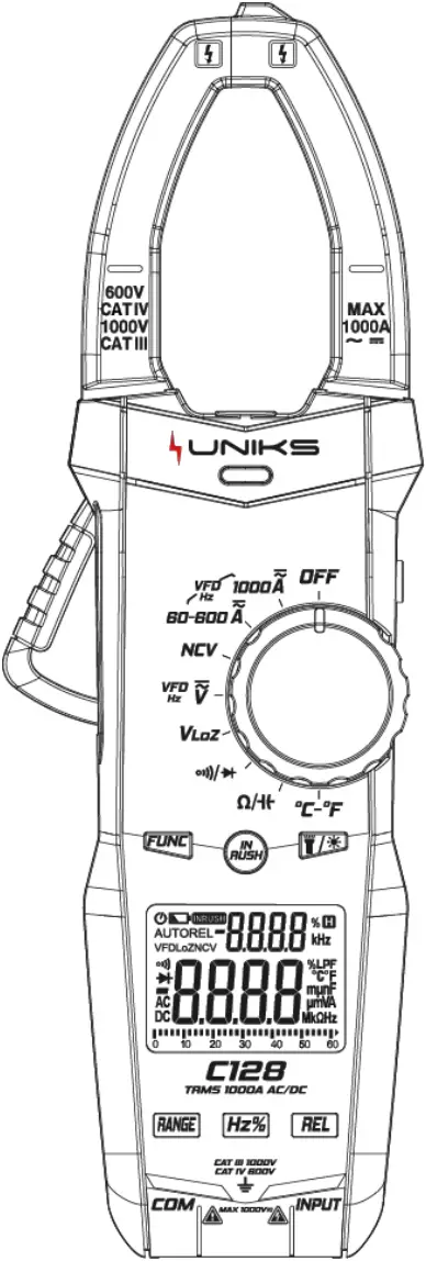
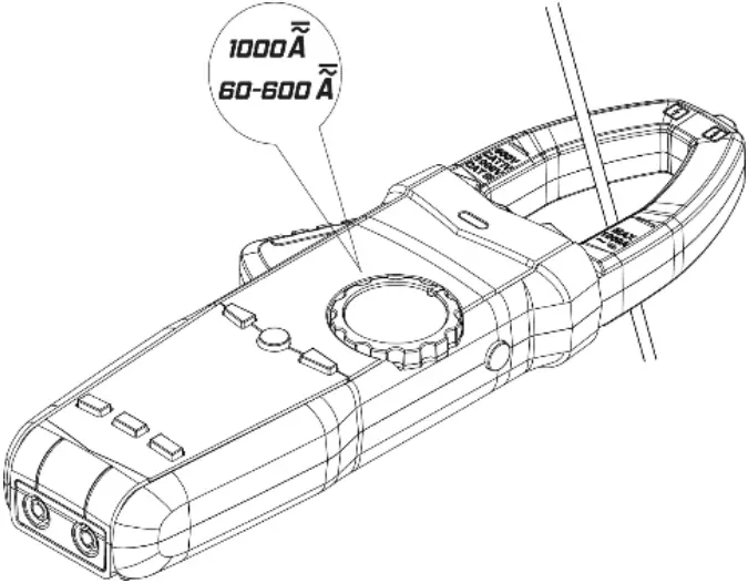
2.2 Instructions to rotary switch
![]() Meter OFF position
Meter OFF position![]() 1000A range (C126 AC and C128 AC/DC)
1000A range (C126 AC and C128 AC/DC)![]() 60A/600A range (C126 AC and C128 AC/DC)
60A/600A range (C126 AC and C128 AC/DC)![]() Non-contact voltage detection
Non-contact voltage detection![]() AC/ DC Voltage measurement
AC/ DC Voltage measurement![]() Low resistance voltage measurement
Low resistance voltage measurement![]() Continuity / Diode Test
Continuity / Diode Test![]() Resistance / Capacitance measurement
Resistance / Capacitance measurement![]() Temperature measurement
Temperature measurement
2.3 LCD display
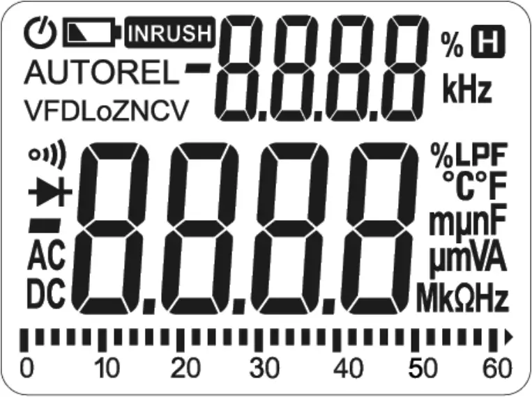
| Automatic shutdown indicate | |
| Battery low voltage indication | |
| inrush current measurement mode | |
| AUTO | Automatic range mode |
| REL | Relative measurement mode |
| VFD | Low pass filter enable prompt |
| LoZ | Low-impedance measurement mode |
| NCV | Non-contact voltage detection |
| Continuity | |
| Diode measurement tips | |
| data negative sign | |
| DC, AC | DC, AC |
| Readings hold status | |
| % | Duty cycle symbol |
| Hz, kHz | Hertz, Kilohertz |
| °C, °F | °C, °F |
| nF, μF, mF | Capacitance unit: nF, μF, mF |
| mA, A | Current value unit: mA, A |
| mV, V | Voltage value unit: mV, V |
| Ω, kΩ, MΩ | Ohm,Kilohm, Megohm (resistance) |
3. Specification
The meter should specify one year as a cycle to re-calibrate in the conditions of 18°C ~ 28°C and relative humidity less than 75%.
3.1 Overview
− Auto and Manual Range
− Overload protection for the whole measurement range.
− Maximum allowable voltage between the measuring terminal and the ground: 1000V DC or 1000V AC
− Work height: maximum 2000m
− Display: LCD
− Maximum display value: 6000 digit.
− Polar indication: automatically indicate,‘-’ means negative polarity
− Over range Indication: ‘0L’ or ‘-0L’
− Sampling time: about 3 times/s,analog strip 10 times/s.
− Unit display: with function and quantity of electricity unit display
− Automatic Power off time: 10 minutes
− Power supply: 1.5V AAA battery ×3
− Battery low voltage indication:LCD display symbol
− Temperature coefficient: < 0.1×accuracy degree/℃
− Working temperature: 18℃ ~ 28℃
− Storage temperature: -10℃ ~ 50℃
3.2 Technical Index
When measuring current, place the conductor to be measured in the center of the clamp head. If not, it can increase ±1.5% position deviation to the maximum
- Mark
- Conductor
3.2.1 AC Current TRMS
Range | Resolution | Accuracy |
| 60A | 0.01A | ± (2.5% reading +8 digits) |
600A | 0.1A | |
| 1000A | 1A |
– Minimum input value of AC current: 0.1A (RMS)
– Maximum input value of AC current: 1000A (RMS)
– Frequency range: 45Hz~1000Hz
3.2.2 DC current (only C128 model)
Range | Resolution | Accuracy |
| 60A | 0.01A | ± (3.0% reading +10 digits) |
600A | 0.1A | |
| 1000A | 1A |
– Minimum input value of DC current: 60mA
– Maximum input value of DC current: 1000A
3.2.3 AC Voltage TRMS
Range | Resolution | Accuracy |
| 6V | 0.001V | ± (0.8% reading +5 digits) |
60V | 0.01V | |
| 600V | 0.1V | |
1000V | 1V | ± (1.0% reading +5 digits) |
– Minimum input value of AC voltage: 1mV (RMS)
– Maximum input value of AC voltage: 1000V (RMS)
– Frequency range: 45Hz~1000Hz
3.2.4 DC Voltage
Range | Resolution | Accuracy |
| 6V | 0.001V | ± (0.5% reading +5 digits) |
60V | 0.01V | |
| 600V | 0.1V | |
1000V | 1V |
– Minimum input value of DC voltage: 1mV
– Maximum input value of DC voltage: 1000V
3.2.5 Frequency / Duty Cycle
3.2.5.1 Current frequency
Range | Resolution | Accuracy |
| 100Hz | 0.01Hz | ± (1.0% reading +5 digits) |
1000Hz | 0.1Hz | |
| 10kHz | 0.001kHz | |
1%-99% | 0.1% | ± (3.0% reading +2 digits) |
– Frequency input range: 10Hz~10kHz
– Input signal range: ≥ 30A AC current (RMS)
3.2.5.2 Voltage Frequency:
Range | Resolution | Accuracy |
| 100Hz | 0.01Hz | ± (1.0% reading +5 digits) |
1000Hz | 0.1Hz | |
| 10kHz | 0.001kHz | |
1%-99% | 0.1% | ± (3.0% reading +2 digits) |
– Frequency input range: 10Hz~10kHz
– Input signal range: ≥ 0.8V AC voltage (RMS)
3.2.6 Continuity
Range | Resolution | Accuracy |
1Ω | If the resistance of circuit being measured is less than 50Ω, then the beeper in the meter may sound |
– Overload protection: 1000V DC or AC (RMS)
3.2.7 Diode
Range | Resolution | Accuracy |
2.000V | 0.001V | Displays approximate value of diode forward voltage drop |
– Overload protection: 1000V DC or AC (RMS)
3.2.8 Resistance
Range | Resolution | Accuracy |
| 600Ω | 0.1Ω | ± (1.0% reading +3 digits) |
6kΩ | 0.001kΩ | |
| 60kΩ | 0.01kΩ | |
600kΩ | 0.1kΩ | |
| 6MΩ | 0.001MΩ | |
60MΩ | 0.01MΩ | ± (1.2% reading +30 digits) |
– Overload protection: 1000V DC or AC (RMS)
3.2.9 Capacitance
Range | Resolution | Accuracy |
| 60.00nF | 0.01nF | ± (4.0% reading +3 digits) |
600.0nF | 0.1nF | |
| 6.000uF | 1nF | |
60.00uF | 10nF | |
| 600.0uF | 100nF | |
6.000mF | 1uF | |
| 60.00mF | 10uF | ± (5.0% reading +5 digits) |
– Overload protection: 1000V DC or AC (RMS)
3.2.10 Temperature
Range | Resolution | Accuracy |
| -20 ~ 1000°C (-4 ~ 1832°F) | 1°C/2°F | ± (2.0% reading +2 digits) |
– Overload protection: 1000V DC or AC (RMS)
4. Operation Guide
4.1 Readings Hold
During the measuring process, if the readings are required to hold, slightly press “![]() ” button, the display value will be locked, slight press “
” button, the display value will be locked, slight press “![]() ” button again to cancel readings hold.
” button again to cancel readings hold.
4.2 Backlight /Light
In the process of measurement, if the ambient light is too dark to read the readings, press “![]() ” button to open the backlight or light:
” button to open the backlight or light:
1) Press “![]() ” button to turn on or off the LCD backlight, and it will turn off automatically about 1 minute after it is turned on.
” button to turn on or off the LCD backlight, and it will turn off automatically about 1 minute after it is turned on.
2) Press and hold “![]() ” button for more than 2 seconds to turn on or off the light. If the light turn on automatically after 1 minute.
” button for more than 2 seconds to turn on or off the light. If the light turn on automatically after 1 minute.
4.3 Auto Power Off
1) If after 10 minutes when the meter is on without any operation, it will go into hibernation and automatically shut down to save power.
2) After auto power off, Turn rotate or press any button except HOLD and REL buttons the dial to wake the meter into working status.
3) When turn the meter on, hold the “![]() ” button at the same time, then the auto power off function is canceled
” button at the same time, then the auto power off function is canceled
4.4 Manual Range
Press the “![]() ” button select the range manually.
” button select the range manually.
4.5 Relative measurements
Press “![]() ” button to enable or disable the relative measurement function. When relative measurement is enabled, the display value will be reset.
” button to enable or disable the relative measurement function. When relative measurement is enabled, the display value will be reset.
4.6 AC/DC current measurement (C126 only AC and C128 AC/DC)
Turn rotary switch to the current measurement level, hold the trigger, open the clamp head, and clamp one cable of the measured circuit, and the meter will display the current value measured.
1) Press “![]() ” button to select AC or DC current measurement. When measuring AC current, touch “
” button to select AC or DC current measurement. When measuring AC current, touch “![]() ” button to toggle the display of the frequency and duty cycle of the measured current. Press and hold “
” button to toggle the display of the frequency and duty cycle of the measured current. Press and hold “![]() ” button for more than 2 seconds to start VFD measurement function.
” button for more than 2 seconds to start VFD measurement function.
2) Press “![]() ” button to turn on the inrush current measurement function while in AC current level.
” button to turn on the inrush current measurement function while in AC current level.
4.7 AC/DC voltage measurement
Turn rotary switch to AC/DC voltage level, press “![]() ” button to switch between AC and DC voltage measurement mode, and connect the probe to the measured signal.
” button to switch between AC and DC voltage measurement mode, and connect the probe to the measured signal.
In DC mode, the red probe is connected to the positive pole of the measured signal and the black probe is connected to the negative pole of the measured signal.
When measuring AC voltage, press “![]() ” button to toggle the display of the frequency and duty cycle of the measured voltage. Press and hold the “
” button to toggle the display of the frequency and duty cycle of the measured voltage. Press and hold the “![]() ” button for more than 2 seconds to start the VFD measurement function.
” button for more than 2 seconds to start the VFD measurement function.
Note: The frequency can only be displayed when the measured value in VFD mode is greater than about 70V.
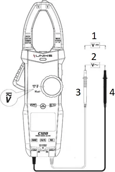
- DC voltage
- AC voltage
- Red
- Black
4.8 Low impedance voltage measurement
Turn rotary switch to “![]() “, press “
“, press “![]() ” button to switch between AC and DC voltage measurement mode to connect the probe to the measured signal.
” button to switch between AC and DC voltage measurement mode to connect the probe to the measured signal.
Note: In low-impedance measurement mode, the longest measurement time shall not be larger than 1 minute.
4.9 Continuity / Diode measurement
Turn rotary switch to “![]() “, press “
“, press “![]() ” button to switch to select the continuity, diode measurement function.
” button to switch to select the continuity, diode measurement function.
1) When choosing the on-off function measurement, the meter will display the resistance value of the measured impedance. When the measured value is less than about 50Ω, the meter buzzer will sound an alarm. When the measured resistance value is greater than about 600Ω, it will display OL.
2) When selecting the diode function for measurement, the red probe is connected to the positive pole of the measured diode and the black probe is connected to the negative pole of the measured diode, the meter displays the approximate value of the diode forward voltage drop. When the probe is connected to the measured diode in reverse, the meter will display OL.
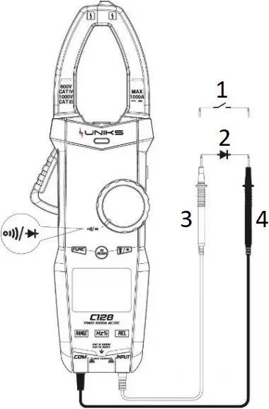
- On-Off
- Diode
- Red
- Black
4.10 Resistance/Capacitance Measurement
Turn rotary switch to “![]() “, press “
“, press “![]() ” button to switch between resistance and capacitance selecting function.
” button to switch between resistance and capacitance selecting function.
1) When resistance measurement is selected, the meter displays the measured resistance value.
2) When capacitance measurement is selected, the meter displays the measured capacitance value.
- Resistance
- Capacitance
- Red
- Black
4.11 Temperature measurement
Turn rotary switch to “![]() “, insert thermocouple probe into input socket, with the positive pole of the probe being connected to red input terminal. The primary display panel will show the measured temperature, Slightly press “
“, insert thermocouple probe into input socket, with the positive pole of the probe being connected to red input terminal. The primary display panel will show the measured temperature, Slightly press “![]() ” button to switch the unit for measuring temperature.
” button to switch the unit for measuring temperature.
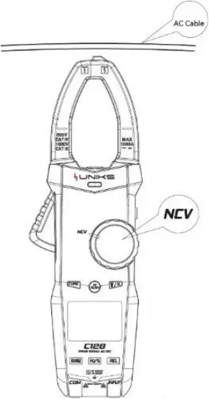
4.12 Non-contact Voltage Detection (NCV)
Turn rotary switch to “![]() “, the meter displays EF. When the NCV sensing area of the meter is close to the measured cable, the charged cable can be judged by the buzzer sound and the LED indicator on the panel.
“, the meter displays EF. When the NCV sensing area of the meter is close to the measured cable, the charged cable can be judged by the buzzer sound and the LED indicator on the panel.
Note:
The detection operation might be affected by various factors such as the socket design and insulation thickness types are different and so on. Even there is no alarm indication, the voltage might still exist. Do not judge if there exist voltage or not in the cable relying on non-contact voltage detector.
5. Maintenance
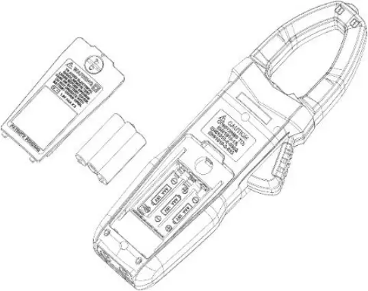
5.1 Replace Battery
![]() WARNING
WARNING
Before opening the battery cover of the meter, the pen-shape meter shall be moved from the measuring circuit first to prevent the risk of electric shock
1) If “![]() ” symbol appears, it means the battery shall be replaced
” symbol appears, it means the battery shall be replaced
2) Screw the fastening screws of the meter battery cover and move away.
3) Replace the old battery.
4) Install the battery cover as previous.
Note: Do not violate the battery polarity
5.2 Replace Pens
![]() WARNING
WARNING
When replacing the pens, the new ones shall be of the same or in equal level. The pens must be in good condition, and level of the pens is: 1000V 10A.
Note
If the insulation layer of the pens is damaged, such as the metal wire of the cable is exposed, then it must be replaced.
6. Accessories
1) Pens Level: 1000V 10A 1
2) Use Manual 1
3) Battery 1.5V AAA battery 3
4) Cloth bag 1
5) K-Type Thermocouple Probe 1
7. ASSISTANCE
7.1 WARRANTY CONDITIONS
This instrument is warranted against defects in materials and workmanship, in accordance with the general terms and conditions. During the warranty period, defective parts can be replaced, but the manufacturer reserves the right to repair or replace the product. If the instrument is to be returned to the after – sales service or to a dealer transportation is borne by the customer. The shipment must, however, be agreed. Attached to dispatch an explanatory note about the reasons of the instrument must always be inserted. For shipping only use the original packaging. Any damage caused by the use of non-original packing shall be charged to the customer. The manufacturer accepts no responsibility for damage caused to people or objects.
The warranty does not apply in the following cases:
- Repair and / or replacement of accessories and battery (not covered by warranty).
- Repairs made necessary because of a misuse of the instrument or of its use with no compatible devices.
- Repairs made necessary due to improper packaging.
- Repairs made necessary due to work carried out by unauthorized personnel.
- Modification of the instrument without the explicit permission of the manufacturer.
- Use not provided for in the specifications of the instrument or in the instruction manual.
The content of this manual may not be reproduced in any form without the permission of the manufacturer.
Our products are patented and their trademarks. The manufacturer reserves the right to change specifications and prices if this is due to technological improvements.
7.2 ASSISTANCE
If the instrument does not operate properly, before contacting the Customer Service, check the status of the battery and wear of the cables and replace them if necessary. If the instrument continues to manifest malfunctions check if the procedure of use of the same is in accordance with what is indicated in this manual. If the instrument is to be returned to the after – sales service or to a dealer transportation is borne by the customer. The shipment must, however, be agreed. Attached to dispatch an explanatory note about the reasons of the instrument must always be inserted. For shipping only use the original packaging; any damage caused by the use of non-original packing shall be charged to the customer.
![]()


Uniks Srl
Via Vittori 57
48018 Faenza (RA), Italy
0546.623002
0546.623691