![]()
GRUNDFOS INSTRUCTIONS
GiM CIU
Installation and operating instructions
be think innovate
General information
![]() Read this document before you install the product. Installation and operation must comply with local regulations and accepted codes of good practice. Read the installation and operating instructions for the relevant CIM module.
Read this document before you install the product. Installation and operation must comply with local regulations and accepted codes of good practice. Read the installation and operating instructions for the relevant CIM module.
Hazard statements
The symbols and hazard statements below may appear in Grundfos installation and operating instructions, safety instructions and service instructions.![]() DANGER Indicates a hazardous situation which, if not avoided, will result in death or serious personal injury.
DANGER Indicates a hazardous situation which, if not avoided, will result in death or serious personal injury.![]() WARNING Indicates a hazardous situation which, if not avoided, could result in death or serious personal injury.
WARNING Indicates a hazardous situation which, if not avoided, could result in death or serious personal injury.![]() CAUTION Indicates a hazardous situation which, if not avoided, could result in minor or moderate personal injury.
CAUTION Indicates a hazardous situation which, if not avoided, could result in minor or moderate personal injury.
The hazard statements are structured in the following way:![]() SIGNAL WORD
SIGNAL WORD
Description of the hazard Consequence of ignoring the warning · Action to avoid the hazard.
Notes
The symbols and notes below may appear in Grundfos installation and operating instructions, safety instructions, and service instructions.![]() Observe these instructions for explosion-proof products.
Observe these instructions for explosion-proof products.![]() A blue or grey circle with a white graphical symbol indicates that an action must be taken.
A blue or grey circle with a white graphical symbol indicates that an action must be taken.![]() A red or grey circle with a diagonal bar, possibly with a black graphical symbol, indicates that an action must not be taken or must be stopped.
A red or grey circle with a diagonal bar, possibly with a black graphical symbol, indicates that an action must not be taken or must be stopped.![]() If these instructions are not observed, it may result in malfunction or damage to the equipment.
If these instructions are not observed, it may result in malfunction or damage to the equipment.
![]() Tips and advice that make the work easier.
Tips and advice that make the work easier.
Product introduction
Product description
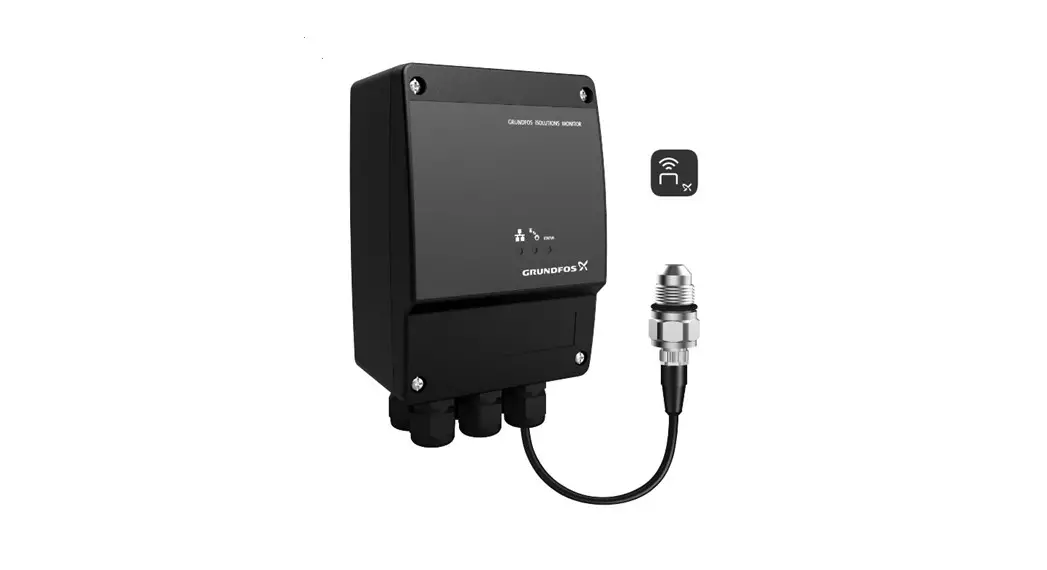
The product monitors the activity of a Grundfos CR, CRE pump. It detects possible irregularities concerning CR, CRE pumps to increase system uptime and keep service and maintenance people on track with pump operation and status for maintenance planning.
GRUNDFOS iSOLUTIONS MONITOR is referred to as “GiM CIU” in this document.
Intended use
The product is intended for use with a Grundfos CR, CRE pump. It can be used for monitoring the pump but not for controlling it.
Applications
The product is used as a communication interface between a Grundfos product and a main network. It is used together with a CIM module (CIM = Communication Interface Module) fitted in the unit.
GENIbus is optional communication between the unit and a Grundfos product.
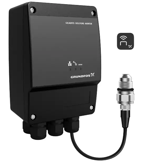
LEDs
The three LEDs are placed on the front cover of the GiM CIU. The Bluetooth button is placed on the bottom on one of the cable glands.
Explanation of the symbols
| Symbol | Description |
| Red and green status LED for the main network. See the installation and operating instructions for the CIM module for more information. | |
| Status LED for the internal communication between the CIM module and the Grundfos product. See the installation and operating instructions for the CIM module for more information. | |
| STATUS | Monitor status. See the following table for descriptions. |
| Bluetooth button for pairing between GiM CIU and Grundfos GO Remote 2.0. |
| STATUS LED | Description |
| Permanently green | The system is working. |
| Flashing green | GiM CIU is in learning mode. |
| Permanently yellow | A warning from the CR pump, for example, high media temperature, vibration or cavitation. It could also be a warning indicating, for example, a VTU sensor fault or missing power for the real-time clock. |
| Permanently red | An alarm from the CR pump, for example, dry run, high media temperature, vibration or cavitation. |
Identification
Nameplate
 TM076071
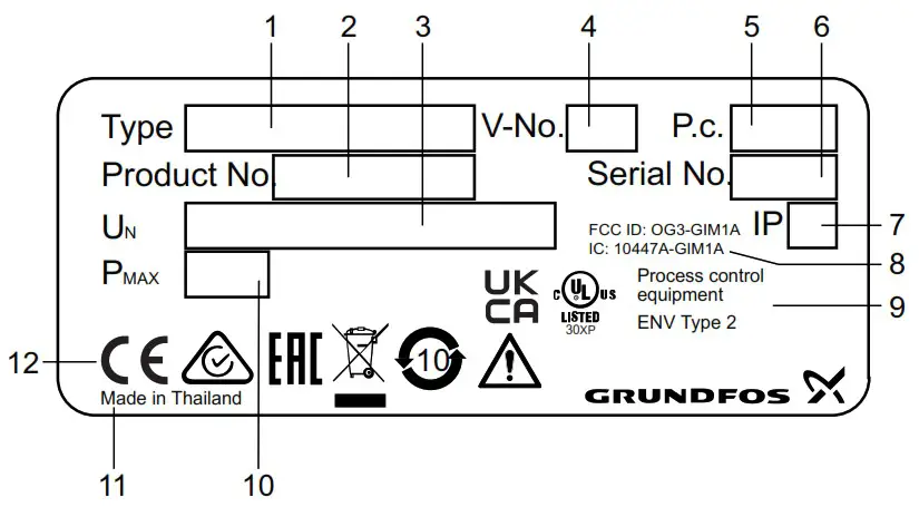
Example of a nameplate
| Pos. | Description |
| 1 | Type designation |
| 2 | Product number |
| 3 | Supply voltage |
| 4 | Version number |
| 5 | Production code (year and week) |
| 6 | Serial number |
| 7 | Enclosure class |
| 8 | FCC and IC text, only for UL variants |
| 9 | Environmental type |
| 10 | Rated power |
| 11 | Production site |
| 12 | Markings and approvals |
Related information
Location
Receiving the product
Inspecting the product
Before installing the product, do the following:
- Check that the product is as ordered.
- Check that no visible parts have been damaged.
- If parts are damaged or missing, contact your local Grundfos sales company.
Scope of delivery
The packaging contains the following items:
- GRUNDFOS iSOLUTIONS MONITOR CIU unit (GiM CIU)
- installation and operating instructions for the product.
Installation requirements
Location
Install the product in a location that meets the following requirements:
- Place the product in a flood-safe place.
- Make sure that the ambient temperature is within the limits.
- Install the product as close as possible to the connected pumps, sensors, and accessories.
- The product must be easily accessible.
- You must install the product in a protective shed or enclosure to avoid direct sunlight and rain.
- Indoor installation: The product must be installed in a well-ventilated room to ensure cooling of its components.
Related information
Nameplate
Technical data
Radio frequency radiation exposure, for Canada and US only
This equipment complies with FCC and ISED radiation exposure limits set forth for an uncontrolled environment. This equipment must be installed and operated with a minimum distance of 20 cm (0.66 feet) between the radiator and your body. FCC ID: OG3-GIM1A IC: 10447A-GIM1A
Mechanical installation
Mounting on the wall
Mount the unit on a surface. The cable glands must face downwards.
CAUTION![]() The product can fall down
The product can fall down
Minor or moderate personal injury ‐ Make sure to use screws that fit into the unit and support its weight.
- All cable screens must be connected to earth. If it is not possible to use cable clamps, the stripped part of the cable screen must be as short as possible to reduce the impedance at high frequencies.
- The cable glands must face downwards.
- Loosen the screws and remove the front cover.
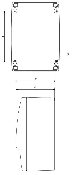
- Drill holes in the surface.
 TM076032
Pos. Dimensions [mm] (inch) 1 115 (4.53″) 2 91 (3.58″) 3 ø4.5 (0.18″) 4 81.5 (3.21″) - Insert wall plugs, if applicable.
- Fit the four screws in the mounting holes and cross-tighten the screws, 1.25 Nm.
 TM076032
Electrical connection
![]() DANGER
DANGER
Electric shock
Death or serious personal injury
- Applies to supply voltages above 30 VRMS / 60 VDC: The installation must incorporate a switch or a circuit breaker in order to switch off the mains supply. It must be close to the CIU unit and easily accessible for the operator. It must be marked as a disconnecting device for the CIU unit.
- In case of an insulation fault, the fault current may be a pulsating DC. Observe national legislation about requirements for and selection of a Residual Current Device (RCD) when installing the pump.
The residual-current circuit breaker must be marked like this:![]()
TM072868
WARNING
Electric shock![]() Death or serious personal injury
Death or serious personal injury
- Switch off the power supply before making any electrical connections. Make sure that the power supply cannot be switched on accidentally.
- The protective earth from the socket outlet must be connected to the protective earth in the pump. Therefore, the applied plug must have the same protective earth connection systems as the socket outlet, or a suitable adapter must be applied.
- Ensure that the high-voltage protection cover is mounted correctly once the installation is finished.
- Tighten the cable glands securely to avoid water coming into the unit or the cables being pulled out.
- The CIU unit and GENIbus must only be connected to SELV or SELV-E circuits.
WARNING![]() Falling off ladder
Falling off ladder
Death or serious personal injury
- Take care when installing the unit on the pump.
CAUTION![]() Hot surface
Hot surface
Minor or moderate personal injury
- Do not touch the pump. The surface may be hot.
![]() All installation work must only be carried out by qualified and authorised persons.
All installation work must only be carried out by qualified and authorised persons.
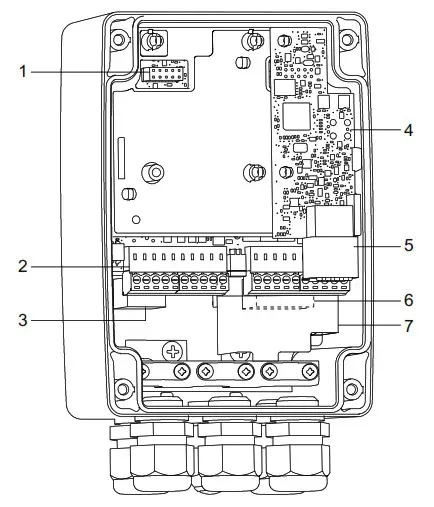 TM076522
| Pos. | Description |
| 1 | CIM connection |
| 2 | IO connections |
| 3 | GENIbus master, connection to the pump |
| 4 | VTU board |
| 5 | Sensor connections |
| 6 | Power supply |
| 7 | High-voltage protection cover |
Related information
6.2 Connecting the power supply
6.3 Connecting GENIbus to the pump
6.4.1 Mounting the sensor cable
6.5 Connecting the IO connections
Terminals
![]() Remember to tighten the cable glands before you switch on the power. The tightening torque is 1.5 Nm.
Remember to tighten the cable glands before you switch on the power. The tightening torque is 1.5 Nm.
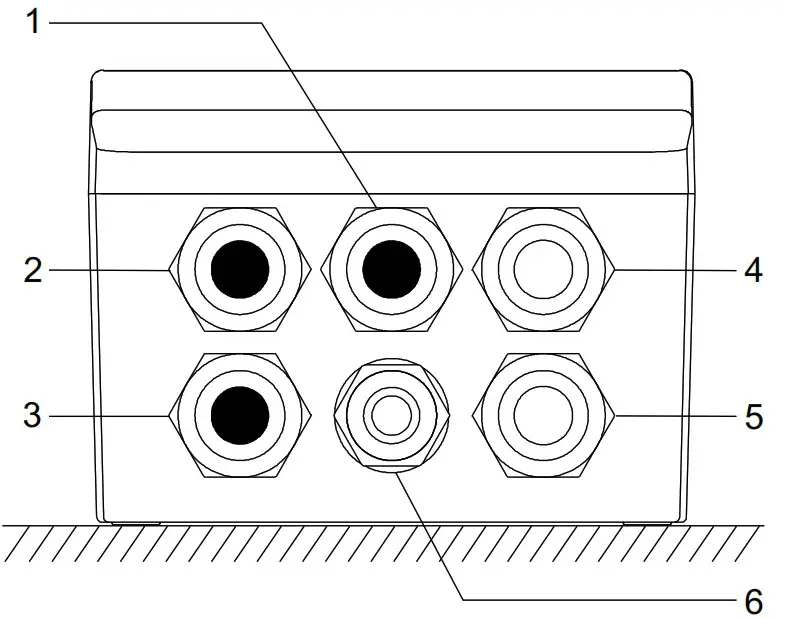
TM076411
| Pos. | Description |
| 1 | Blank (default) Options: antenna, Ethernet or IO |
| 2 | Blank (default) Options: antenna, Ethernet or IO |
| 3 | Blank (default) Options: GENIbus master (pump) or IO |
| 4 | VTU sensor |
| 5 | Power supply |
| 6 | Bluetooth connect button |
Connecting the power supply
WARNING
Electric shock
Death or serious personal injury
- Make sure there is proper insulation around the supply cable.
- The protective earth wire must be longer than the neutral and phase wires.
- Remove the front cover.
- Remove the sensor connector and the IO connections.
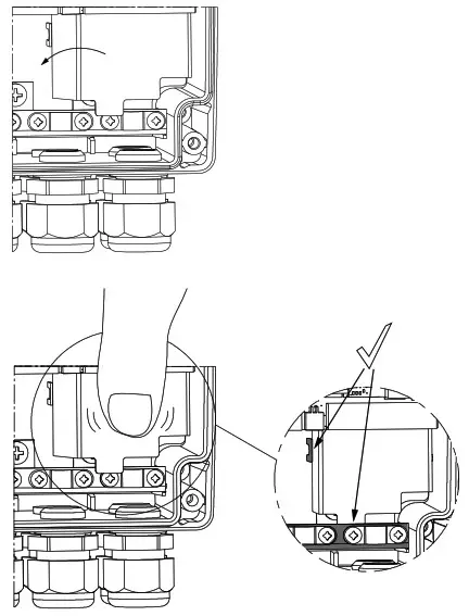
- Pull the high-voltage protection cover upwards to access the connectors.
- Lead the supply cable through the cable gland.
- Connect the supply conductors to earth, N and L.
- Tighten the cable glands.
- Fit the high-voltage protection cover again.
 TM077422
TM077423
Push the cover down firmly - Fit the front cover.
 TM077422
Example:
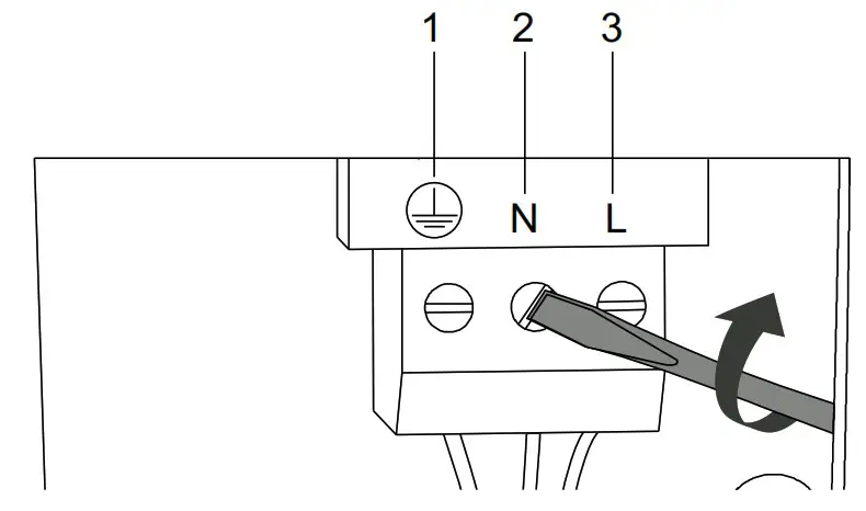 TM076416
| Pos. | Description |
| 1 | Protective earth terminal |
| 2 | Neutral terminal |
| 3 | Phase terminal |
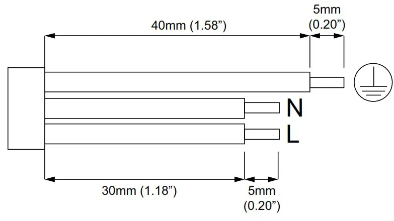
Wire requirements
Related information
6. Electrical connection
6.3 Connecting GENIbus to the pump
6.5 Connecting the IO connections
Connecting GENIbus to the pump
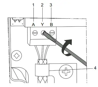
- Remove the front cover.
- Lead the GENIbus cable through the cable gland.
- Connect the conductors to terminals A, Y and B.
- Connect the cable screen under the earth clamp, and tighten the earth clamp.
- Tighten the cable gland.
- Fit the front cover.
Example:
TM076415
GENIbus connection
| Pos. | Designation | Description |
| 1 | A | GENIbus terminal A. Positive data signal. |
| 2 | Y | GENIbus terminal Y |
| 3 | B | GENIbus terminal B. Negative data signal. |
| 4 | – | Earth clamp |
Related information
6. Electrical connection
6.2 Connecting the power supply
Sensor cable
WARNING![]() Fall hazard
Fall hazard
Death or serious personal injury
- Follow local working environment regulations.
Mounting the sensor cable
- Read the GiM quick guide to see how to mount the sensor cable.
 net.grundfos.com/qr/i/99802939
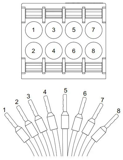
| Pos. | Colour | Designation | Description |
| 1 | White | DR | Dry run |
| 2 | Brown | V+ | Supply |
| 3 | Green | GND | Ground |
| 4 | Yellow | Rw1 | Pt100 |
| 5 | Grey | Rw2 | Pt100 |
| 6 | Pink | Vin | Analog |
| 7 | Blue | GND | Ground |
| 8 | Red | GND | Ground |
For more information on the VTU sensor, see the data sheet.

net.grundfos.com/qr/i/99873130
Related information
6. Electrical connection
Connecting the IO connections
WARNING
Electric shock![]() Death or serious personal injury
Death or serious personal injury
- The IO connections of the GIM CIU unit must be connected to SELV or SELV-E circuits only.
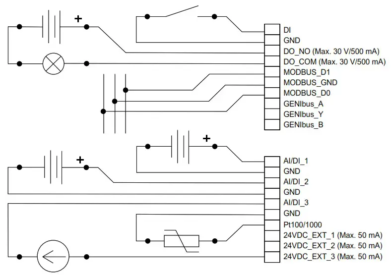
Wiring diagram
Options for configuration of connections
| Electrical signals | DI | AI/DI 1 | AI/DI 2 | AI/DI 3 | Pt100(0) |
| Digital input | x | ||||
| Analog input, 0 – 20 mA | x | x | x | ||
| Analog input, 4 – 20 mA | x | x | x | ||
| Analog input, 0 – 10 V | x | x | x | ||
| Analog input, 0 – 5 V | x | x | x | ||
| Analog input, 0.5 – 3.5 V | x | x | x | ||
| Pt100 | x | ||||
| Pt1000 | x |
Related information
6. Electrical connection
6.2 Connecting the power supply
- Connect the input and output terminals according to the drawing.
Starting up the product
Connecting the unit to Grundfos GO Remote 2.0
Before connecting the product, the Grundfos GO Remote 2.0 app must be downloaded to your smartphone or tablet. The app is free of charge and available for iOS and Android devices.
![]() CAUTION
CAUTION
Radiation
Minor or moderate personal injury
- Human tissue may be heated by RF energy. Locate the antenna at a minimum distance of 20 cm (7.87 inches) from any body parts.
- Open Grundfos GO Remote 2.0 on your device. Make sure that Bluetooth is enabled. Your device must be within reach of the product to establish Bluetooth connection.
- Press the connect icon in Grundfos GO Remote 2.0.
- Press the connect button on the product. The blue LED is flashing until your device is connected. Once the connection is established, the LED is permanently on. Grundfos GO Remote 2.0 is now loading the data for the product.
- Refer to the GiM quick guide for further information regarding startup.
net.grundfos.com/qr/i/99802939
Servicing the product
The product cannot be serviced.
- Contact Grundfos. If the product is faulty, it must be replaced.
Cleaning the product
The product must only be cleaned with a clean dry or a soapy damp cloth.
Technical data
Electrical supply
| Transient overvoltage | Category II |
| Supply voltage | 24-240 VAC/VDC, ± 10 % |
| Frequency | DC, 50/60 Hz |
| Max. power consumption | 11 W |
Cables
| Power supply cable | IEC: 0.75 – 4 mm UL: 18 – 12 AWG Use a 3-core cable thatmeets the requirements of the National Electric Code.
Use copper or copperclad aluminum conductors only. Use a power cable with an outer diameter of ø6 10 mm only. |
| Recommended communication cable | Screened, double twisted-pair Cross-section: 0.2 – 0.3 mm 2 AWG: 24 – 22 Maximum cable length: 1200 m (4000 ft) Use a communication cable with an outer diameter of ø4 – 10 mm. |
| Cable entry | 5 x M16 ø3.5 – 10 mm clamping range |
Fuses
| Back-up fuse | Maximum 10 A. Both standard fuses as well as quick- and slow-blow fuses are suitable. |
| Short-circuit protection | Use fuses that comply with IEC 60127. USA and Canada (branch circuit protection): Use a UL/CSA listed non-time delay (high capacity) fuse that complies with the UL248 series or an inverse time circuit breaker that complies with UL489. Fuse types RK1, RK5, J, and CC are acceptable. |
GENIbus master, for pump connection
| Transceiver | RS-485 |
| Protocol | GENIbus |
| Parity | None |
| Stop bits | 1 |
| Transmission speed | 9600 bit/s |
GENIbus connection, for Grundfos GO Remote PC
| Transceiver | RS-485 |
| Protocol | GENIbus |
| Parity | None |
| Stop bits | 1 |
| Transmission speed | 9600 (default), 19200, 38400, 115200 bit/s |
Modbus RTU
| Transceiver | RS-485 |
| Protocol | Modbus |
| Parity | None, odd, even (default) |
| Stop bits | 1 (default), 2 |
| Modbus address | 1-247. Default: 247. |
| Transmission speed | 9600 (default), 19200, 38400 bit/s |
Environmental conditions
| Max. altitude above sea level | 2000 m (6562 ft) |
| Relative humidity | 95 %, non-condensing |
| Pollution degree | Category 3 |
| Enclosure class | IP54 according to IEC 60529 Type 2 according to UL 50 For indoor use only. |
Ambient temperature
| During operation | -20 to +45 °C (-4 to +113 °F) |
| During storage | -20 to +60 °C (-4 to +140 °F) |
| During transport | -20 to +60 °C (-4 to +140 °F) |
Related information
4.1 Location
Disposing of the product
This product or parts of it must be disposed of in an environmentally sound way.
- Use the public or private waste collection service.
- If this is not possible, contact the nearest Grundfos company or service workshop.
 The crossed-out wheelie bin symbol on a product means that it must be disposed of separately from household waste. When a product marked with this symbol reaches its end of life, take it to a collection point designated by the local waste disposal authorities. The separate collection and recycling of such products will help protect the environment and human health.
See also end-of-life information at www.grundfos.com/product-recycling.
A.1. FCC/ISED general requirements
This device complies with FCC and ISED radiation exposure limits set forth for an uncontrolled environment. This device must be installed and operated with a minimum distance of 20 cm (7.87 inches) between the radiator and your body. This transmitter must not be co-located or operated in conjunction with any other antenna or transmitter.
FCC![]() This device complies with Part 15 of the FCC Rules. Operation is subject to the following two conditions:
This device complies with Part 15 of the FCC Rules. Operation is subject to the following two conditions:
- This device may not cause harmful interference, and
- This device must accept any interference received, including interference that may cause undesired operation.
![]() Changes or modifications made to this equipment not expressly approved by Grundfos may void the user’s authority to operate this equipment.
Changes or modifications made to this equipment not expressly approved by Grundfos may void the user’s authority to operate this equipment.
ISED![]() This device complies with ISED’s license-exempt RSSs. Operation is subject to the following two conditions:
This device complies with ISED’s license-exempt RSSs. Operation is subject to the following two conditions:
- This device may not cause harmful interference, and
- This device must accept any interference received, including interference that may cause undesired operation.
![]() Changes or modifications made to this equipment not expressly approved by Grundfos may void the user’s authority to operate this equipment.
Changes or modifications made to this equipment not expressly approved by Grundfos may void the user’s authority to operate this equipment.
This radio transmitter (IC: 10447A-GIM1A) has been approved by ISED to operate with Grundfos cellular module CIM 280-US (IC: 10447A-CIM2X034G). Only the original Grundfos supplied antenna, part no. 99838775, is permitted.
The maximum antenna gain is:
| CDMA850/LTE B5 | +0.3 dBi (824-849 MHz) |
| CDMA1900/LTE B2 | -1.2 dBi (1850-1910 MHz) |
| LTE B4 | +1.5 dBi (1710-1755 MHz) |
| LTE B17 | -7.0 dBi (704-716 MHz) |
| LTE B12 | -7.0 dBi (698-716 MHz) |
| LTE B13 | -5.0 dBi (777-787 MHz) |
Bluetooth information
| Frequency of operation | 2400 – 2483.5 MHz (ISM band) |
| Modulation type | GFSK |
| Data rate | 1 Mbps |
| Transmit power | 5 dBm EIRP with internal antenna |
A.2. Exposition aux radiations de fréquence radio
Declaration of conformity
We, Grundfos, declare under our sole responsibility that the product GiM CIU, to which the declaration below relates, is in conformity with the Council
Directives listed below on the approximation of the laws of the EU member states.
- Radio Equipment Directive 2014/53/EU. Standards used:
EN 61010-1:2010
EN 301 489-1 ver. 2.2.0
EN 301 489-17 ver. 3.2.4
EN 301 489-52 ver. 1.3.1
EN 301 908-1 ver. 11.1.1
EN 301 908-2 ver. 1.1.2
EN 301 908-13 ver. 11.1.2
EN 301 511 ver. 12.5.1
EN 300 328 ver. 2.2.0 - RoHS 2 Directives (2011/65/EU and 2015/863/EU).
Standard used: EN IEC 63000:2018
This EC declaration of conformity is only valid when published as part of the Grundfos installation and operating instructions (publication number 99802941). Bjerringbro, 1/November/2020
 Senior Manager
United Kingdom
GRUNDFOS Pumps Ltd. Grovebury Road Leighton Buzzard/Beds. LU7 4TL
Tel.: +44-1525-850000
Fax: +44-1525-850011
U.S.A.
GRUNDFOS Water Utility Head Quarters Brookshire, Texas 77423 USA
99802941
ECM 1299999
© 2020 Grundfos Holding A/S, all rights reserved.
Trademarks displayed in this material, including but not limited to Grundfos, the Grundfos logo and “be think innovate” are registered trademarks owned by The Grundfos Group. All rights reserved.
References
 net.grundfos.com/qr/i/99802939
-
net.grundfos.com/qr/i/99873130
 Slovak (Slovakia) | The full range supplier of pumps and pump solutions. As a renowned pump manufacturer, Grundfos delivers efficient, reliable, and sustainable solutions all over the globe. Step into our world.
 Bosnian (Bosnia) | The full range supplier of pumps and pump solutions
-
Dansk (Danmark) | Den komplette leverandør af pumper og pumpeløsninger. Som en berømt pumpeproducent leverer Grundfos effektive, pålidelige og bæredygtige løsninger over hele kloden. Gå ind i vores verden.
-
Product sustainability | Grundfos


