![]()
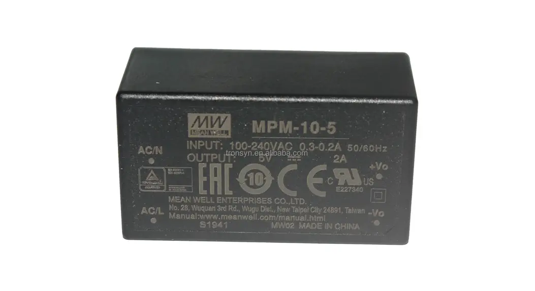
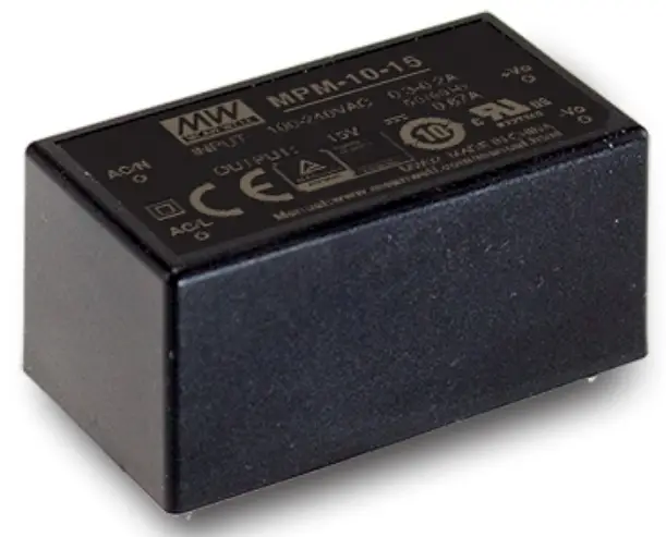
10W High Reliable Green Medical Encapsulated Type
M P M – 1 0 s e r i e s

https://www.meanwell.com/Upload/PDF/PCB_EN.pdf


Features
- 1.8″x1″ compact size
- Medical safety approved (2 x MOPP) according to ANSI/AAMI ES60601-1 and IEC/BS EN/EN60601-1
- Suitable for BF application with appropriate system consideration
- No load power consumption<0.075W
- Extremely low leakage current
- Wide operating temp. range -30 – +85°C
- EMI class B for class II configuration
- Protections: Short circuit / Overload / Over voltage / Over temperature
- No minimum load required
- 3 years warranty
Applications
- Portable medical device
- Mobile clinical workstation
- Medical computer monitor
- Medical examination instrument
GTIN CODE
MW Search https://www.meanwell.comiserviceGTIN.aspx
Description
MPM-10 is a 10W high density and small size (45.7*25.4*21.5mm) AC/DC module type medical grade power supply series offered in pin type. It features the operation for 80-264VAC, a low no load power consumption less than 0.075W, a high efficiency up to 84%, Class II (no FG) double insulation, outstanding dissipation and high lifespan thanks to the interior potting, 50 anti-vibration, high EMC performance, 4KVAC isolation, etc. The design observes IEC/BS EN/EN60601-1 and ANSI/AAMI ES60601-lversion three with 2xMOPP level and ultra-low leakage current (<80 p A). It is very suitable for BF (patient contact) type medical device or relevant equipment.
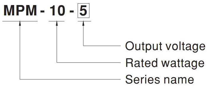
Model Encoding
SPECIFICATION
| MODEL | MPM-10-3.3 | MPM-10-5 | MPM-10-12 | MPM-10-15 | MPM-10-24 | |||
| OUTPUT | DC VOLTAGE | 3.3V | 5V | 12V | 15V | 24V | ||
| RATED CURRENT | 2.5A | 2A | 0.85A | 0.67A | 0.42A | |||
| CURRENT RANGE Note.2 | 0 ~ 2.5A | 0 ~ 2A | 0 ~ 0.85A | 0 ~ 0.67A | 0 ~ 0.42A | |||
| PEAK CURRENT | 2.75A | 2.2A | 0.94A | 0.74A | 0.46A | |||
| RATED POWER | 8.3W | 10W | 10.2W | 10W | 10W | |||
| PEAK LOAD(10sec.) Note.3 | 9W | 11W | 11.3W | 11.1W | 11W | |||
| RIPPLE & NOISE (max.) Note.4 | 120mVp-p | 100mVp-p | 180mVp-p | 180mVp-p | 200mVp-p | |||
| VOLTAGE TOLERANCE Note.5 | ±2.5% | ±2.5% | ±2.5% | ±2.5% | ±2.5% | |||
| LINE REGULATION | ±0.3% | ±0.3% | ±0.3% | ±0.3% | ±0.3% | |||
| LOAD REGULATION | ±0.5% | ±0.5% | ±0.5% | ±0.5% | ±0.5% | |||
| SETUP, RISE TIME | 1000ms, 30ms/230VAC 1000ms, 30ms/115VAC at full load | |||||||
| HOLD UP TIME (Typ.) | 40ms/230VAC 8ms/115VAC at full load | |||||||
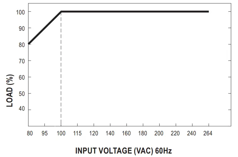
| INPUT | VOLTAGE RANGE Note.6 | 80 ~ 264VAC | ||||||
| FREQUENCY RANGE | 47 ~ 440Hz | |||||||
| EFFICIENCY (Typ.) | 78% | 81% | 83% | 83% | 84% | |||
| AC CURRENT (Typ.) | 0.3A/115VAC 0.2A/230VAC | |||||||
| INRUSH CURRENT (Typ.) | COLD START 25A/115VAC 45A/230VAC | |||||||
| LEAKAGE CURRENT (max.) Note.7 | Touch current <80μA/264VAC | |||||||
| PROTECTION | OVERLOAD | 110% ~ 180% rated output power | ||||||
| Protection type : Hiccup mode, recovers automatically after fault condition is removed | ||||||||
| OVER VOLTAGE | 3.8 ~ 5V | 5.8 ~ 6.8V | 13.8 ~ 16.2V | 17.3 ~ 20.3V | 27.6 ~ 32.4V | |||
| Protection type : Shut off o/p voltage, clamping by zener diode | ||||||||
| OVER TEMPERATURE | Protection type : Shut down o/p voltage, recovers automatically after temperature goes down | |||||||
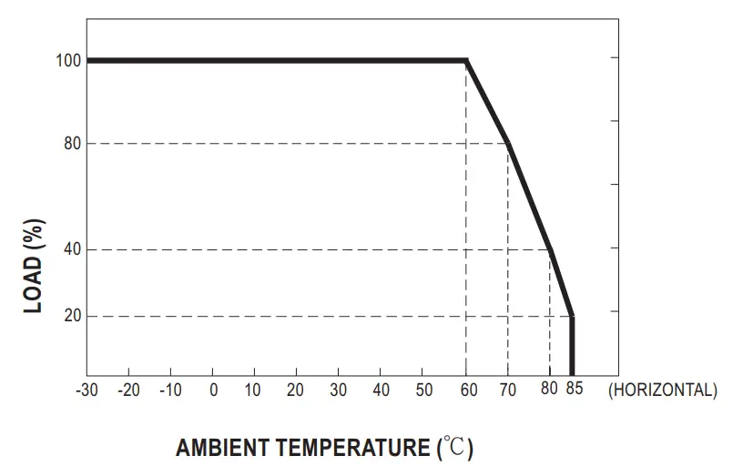
| ENVIRONMENT | WORKING TEMP. | -30 ~ +85℃ (Refer to “Derating Curve”) | ||||||
| WORKING HUMIDITY | 20 ~ 90% RH non-condensing | |||||||
| STORAGE TEMP., HUMIDITY | -40 ~ +100℃, 10 ~ 95% RH non-condensing | |||||||
| TEMP. COEFFICIENT | ±0.03%/℃ (0 ~ 60℃) | |||||||
| SOLDERING TEMPERATURE | Wave soldering: 265℃,5s (max.); Manual soldering: 390℃,3s (max.) | |||||||
| VIBRATION | 10 ~ 500Hz, 5G 10min./1cycle, period for 60min. each along X, Y, Z axes | |||||||
| OPERATING ALTITUDE Note.8 | 5000 meters | |||||||
| SAFETY & EMC (Note 9) | SAFETY STANDARDS | IEC60601-1, BS EN/EN60601-1, EAC TP TC 004, UL ANSI/AAMI ES60601-1(3.1 version), CAN/CSA-C22 3rd Edition approved ; Design refer to BS EN/EN60335-1(by request) | ||||||
| ISOLATION LEVEL | Primary-Secondary: 2xMOPP | |||||||
| WITHSTAND VOLTAGE | I/P-O/P:4KVAC | |||||||
| ISOLATION RESISTANCE | I/P-O/P:100M Ohms / 500VDC / 25℃/ 70% RH | |||||||
| EMC EMISSION | Parameter | Standard | Test Level / Note | |||||
| Conducted | BS EN/EN55011 (CISPR11) | Class B | ||||||
| Radiated | BS EN/EN55011 (CISPR11) | Class B | ||||||
| Harmonic Current | BS EN/EN61000-3-2 | Class A | ||||||
| Voltage Flicker | BS EN/EN61000-3-3 | —– | ||||||
| EMC IMMUNITY | BS EN/EN55035, BS EN/EN60601-1-2 | |||||||
| Parameter | Standard | Test Level / Note | ||||||
| ESD | BS EN/EN61000-4-2 | Level 4, 15KV air ; Level 4, 8KV contact | ||||||
| RF field susceptibility | BS EN/EN61000-4-3 | Level 3, 10V/m(80MHz~2.7GHz ) Table 9, 9~28V/m( 385MHz~5.78GHz ) | ||||||
| EFT bursts | BS EN/EN61000-4-4 | Level 3, 2KV | ||||||
| Surge susceptibility | BS EN/EN61000-4-5 | Level 3, 1KV/Line-Line | ||||||
| Conducted susceptibility | BS EN/EN61000-4-6 | Level 3, 10V | ||||||
| Magnetic field immunity | BS EN/EN61000-4-8 | Level 4, 30A/m | ||||||
| Voltage dip, interruption | BS EN/EN61000-4-11 | 100% dip 1 periods, 30% dip 25 periods, 100% interruptions 250 periods | ||||||
| OTHERS | MTBF | 9314.1K hrs min. Telcordia SR-332 (Bellcore) ; 1756.2K hrs min. MIL-HDBK-217F (25℃) | ||||||
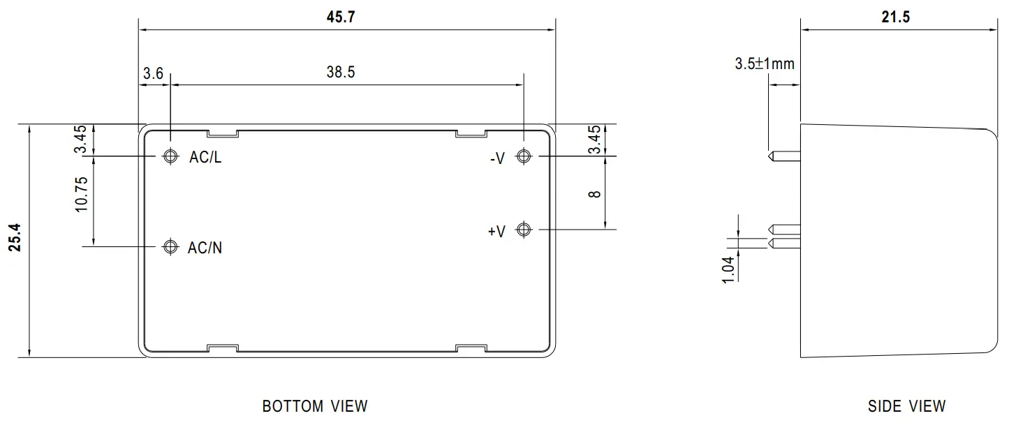
| DIMENSION | 45.7*25.4*21.5mm (L*W*H) or 1.8*1.0″0.85″ inch | |||||||
| PACKING | 0.035Kg; 270pcs/10.5Kg/0.94CUFT | |||||||
| NOTE | 1. All parameters NOT specially mentioned are measured at 230VAC input, rated load and 25℃ of ambient temperature. 2. No minimum load required. 3. 33% Duty cycle maximum within every 30 seconds. Average output power should not exceed the rated power 4. Ripple & noise are measured at 20MHz of bandwidth by using a 12″ twisted pair-wire terminated with a 0.1μf & 47μf parallel capacitor. 5. Tolerance : includes set up tolerance, line regulation and load regulation. 6. Derating may be needed under low input voltages. Please check the derating curve for more details. 7. Touch current was measured from primary input to DC output. 8. The ambient temperature derating of 3.5℃/1000m with fanless models and of 5℃/1000m with fan models for operating altitude higher than 2000m(6500ft). 9. The power supply is considered a component which will be installed into a final equipment. The final equipment must be re-confirmed that it still meets EMC directives. For guidance on how to perform these EMC tests, please refer to “EMI testing of component power supplies. (as available on http://www.meanwell.com) ※ Product Liability Disclaimer:For detailed information, please refer to https://www.meanwell.com/serviceDisclaimer.aspx | |||||||
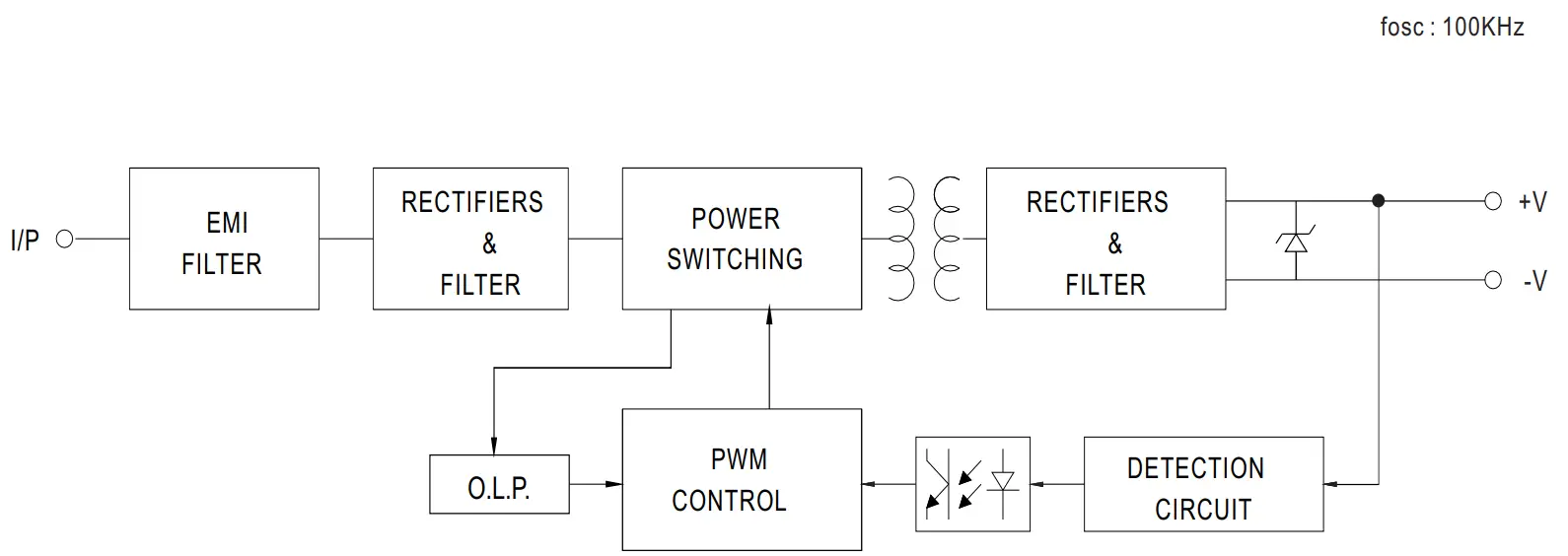
Block Diagram
Derating Curve
Output Derating VS Input Voltage
Mechanical Specification
Installation Manual
Please refer to : http://www.meanwell.com/manual.html
![]()


