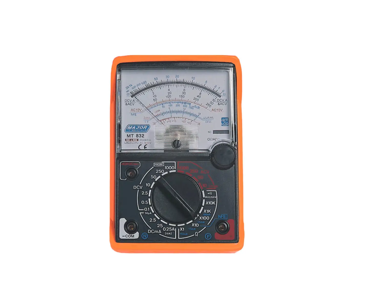
MAJOR TECH MT832 Analogue Multimeter
- READ and UNDERSTAND all of the instructions and safety information in this manual before operating or servicing this instrument!
- Keep this instruction manual handy all the time, it will help you use this instrument easily in the future!
FEATURES
- 8 Functions 20 measuring ranges.
- Fuse and diode protection
- Functions: AC/DC Voltage test, DC Current test, Resistance test, Transistor test and hFE test
SPECIFICATIONS
REFERENCE TABLE FOR READING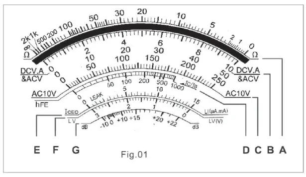
Note:
The letter “A” to “G” in Scale to Read, please refer to Fig.01
| Test | Range Position | Scale to Read | Multiplyer |
|
DC Voltage | DC 0.1V 0.5V 2.5V 10V 50V 250V 1000V | B 10 B 50 B 250 B 10 B 50 B 250 B 10 | x0.01 x0.01 x0.01 x1 x1 x1 x100 |
| AC Voltage | AC 10V 50V 250V 1000V | C 10 B 50 B 250 B 10 | x1 x1 x1 x100 |
| DC Current | DC 50μA 2.5mA 25mA 0.25A | B 50 B 250 B 250 B 250 | x1 x0.01 x0.1 x0.001 |
| Resistance | x1 x10 x100 x1K x10K | A A A A A | x1 x10 x100 x1000 x10000 |
| Decibel | AC 10V 50V 250V | G G G | x1 x1 + 14dB x1 + 28dB |
| lceo | x1 x10 | E E | x1 (For big) x1 (For small) |
| hFE | x10 | D | x1 |
RANGE SEPCIFICATIONS
| Function | Range | Accuracy | |
| DC Voltage | 0.1-0.5-2.5-10-50 -250-1000V | Full Scale Deflection: 3 (1000V:5) | |
| Sensitivity: 20kΩ/V | |||
| Extension: 25kV* | |||
| AC Voltage 40 to 60Hz | 10-50-250-1000V | Full Scale Deflection: 4 (1000V: 5) | |
| Sensitivity: 9kΩ/V | |||
| Decibel Meter | -10 to +22dB (0db=1mW/600Ω) | ||
| DC Current | 50μA (0.1V DC Position), 2.5mA, 25mA, 0.25A | Full Scale Deflection: 3 | |
|
Resistance | Range Position | x1: 0.2Ω up to 2kΩ, Mid-scale at 20Ω |
Full Scale Deflection: 3 |
| x10: 2Ω up to 20kΩ, Mid-scale at 200Ω | |||
| x100: 20Ω up to 200kΩ, Mid-scale at 2kΩ | |||
| x1k: 200Ω up to 2MΩ, Mid-scale at 20kΩ | |||
| x10k: 2kΩ up to 20MΩ, Mid-scale at 200kΩ | |||
| Iceo | 150μA-1.5mA – 15mA-150mA | ||
| hFE | 0-1000 (With connection extra) | ||
| Standard | lEC61326 CATII 600V, Pollution degree II, CE approved | ||
*An extra high voltage probe is required for this test (probe not included)
METER DESCRIPTION
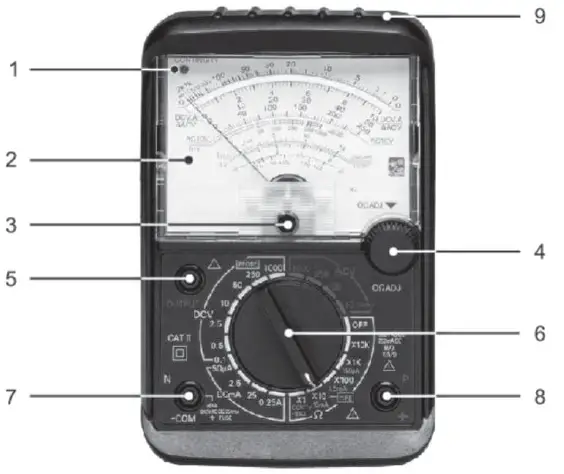
- Continuity Indicator
- Reading Panel
- Zero Corrector
- 0Ω Adjusting Knob
- Output Terminal (Series Condenser)
- Function Switch
- Measuring Terminal (-)/COM (COMMON)
- Measuring Terminal(+)
- Plastic Protection Cover
OPERATION
WARNING:
- Before using this instrument, please adjust the ZERO by Zero Corrector.
- When measuring the Resistance, make sure that there is no voltage in the circuit.
- ALWAYS turn the function switch to the OFF position when the meter is not in use.
RESISTANCE TEST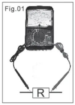
- Set the function switch to the highest Ω position.
- Insert the test leads into COM (Black lead) and “+” socket (Red lead)
- Short the test leads and turn 0Ω adjusting knob to set the pointer to zero position.
- Make sure that there is no voltage across the circuit to be tested.
- Connect the test leads to the tested resistor (Fig.01) and read the scale in accordance with the reference table. Reset the function switch to successively lower Ω positions to obtain a higher resolution reading.
CONTINUITY TEST (BUZZ AND LED)
- Plug the test leads into COM (Black lead) and “+” socket (Red lead)
- Set the range function switch to BZ/CONT’Y position, apply the test lead pins to two points to be tested. While tested circuit is continuous it should indicate to you as below:
- A. Buzz and LED lighting (ln on to 300),
- B. Only the LED lighting (Up to 300).
WARNING: It is impossible to test a point where voltage is being applied.
DCV TEST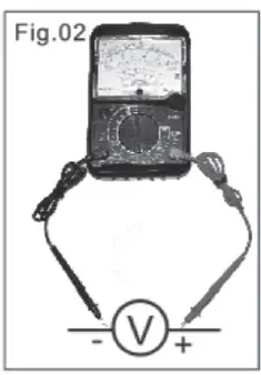
- Set the function switch to the highest VDC position.
- Insert the test leads into COM (Black lead) and “+” socket (Red lead)
- Connect the red test lead to the polarity of the circuit tested and the black one to the negative. (Fig.02)
- Read the DCV.A scale converted with the reference table. Reset the function switch to successively lower VAC positions to obtain a higher resolution reading.
Note: The voltmeter is connected in parallel. (Fig.02)
ACV TEST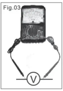
- Set the function switch to the highest ACV position.
- Insert the test leads into COM (Black lead) and “+” socket (Red lead)
- Connect the test leads to the circuit being tested, regardless of the polarities. (Fig.03)
- Read ACV scale with the reference table. Reset the function switch to successively lower ACV positions to obtain a higher resolution reading.
DECIBEL
Do this test as the ACV TEST, but read the decibel scale with the reference table of decibel not the ACV.
DCA TEST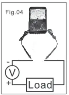
- Set the function switch to the highest DCA position.
- Insert the test leads into COM (Black lead) and “+” socket (Red lead)
- Remove power from the circuit under test, then open up the circuit at the point where you wish to measure current. (Fig.04)
- Read the DCV.A scale converted with the reference table. Reset the function switch to successively lower ACV positions to obtain a higher resolution reading.
ACV TEST ON OUTPUT TERMINAL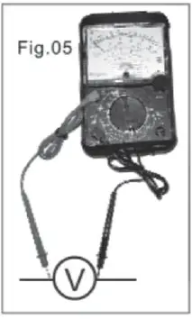
- Set the function switch to the highest DCV position.
- Insert the test leads into COM (Black lead) and “OUTPUT” socket (Red lead)
- Connect the test leads to the circuit to be tested and read the scale in the same manner as DCV test. Reset the function switch to successively lower ACV positions to obtain a higher resolution reading.(Fig.05)
Note: 1. The voltmeter is connected in parallel. 2. Such a measurement is made to block the DC voltage which 1 presents in the same circuit and must be cut so that AC voltage can be read alone.
Iceo (LEAKAGE CURRENT) TEST
- Insert the test leads into COM (Black lead) and “+” socket (Red lead).
- Set the function switch to X10 (15mA) for small size transistor, or to X1 (150mA) for big size transistor.
- Short the test leads and turn on adjusting knob to set the pointer to the zero position.
- Making Measurement:
- A. For NPN transistor, the “N” terminal of the tester is connected to the COLLECTOR (C) of the transistor, the “P” terminal is connected to the EMITTER (E) of the transistor.
- B. For PNP transistor, reverse the connection of NPN transistor connect.
- For the lceo range, if the pointer is not within the LEAK zone or the pointer moves up near to the full scale, it means that the transistor is not good. Otherwise, it is a good transistor.
hFE (DC AMPLIFICATION) TEST
- Insert the test leads into COM (Black lead) and “+” socket (Red lead).
- Set the function switch to X10.
- Short the test leads and turn on 0Ω adjusting knob to set the pointer to zero position.
- Making Measurement:
- A. For NPN FE transistor.
- ii. Plug the hFE connector into “N” terminal and connect its red clip to the collector and the black one to the base of the transistor.
- B. For the PNP transistor,
- i. Connect the “N” terminal of the tester to the emitter of the transistor.
- ii. Plug the hFE connector into the “P” terminal and connect the clips in the same way as NPN transistor connection.
- A. For NPN FE transistor.
- Read the hFE scale. The value of the reading is lc/lb, which is the DC amplication degree of the transistor.
BATTERY REPLACEMENT
- Take out the plastic protection cover first
- Remove Philips head screw and lift off the rear housing of the meter.
- Replace old battery with fresh 9V and AA type battery.
- Replace the rear cover and secure the screw.
WARNING: Disconnect the test leads from any source of voltage before removing the back cover or the battery/fuse door. Do not operate your meter until the rear housing is in place and fastened securely.
South Africa
www.major-tech.com
[email protected]
Australia
www.majortech.com.au
[email protected]


