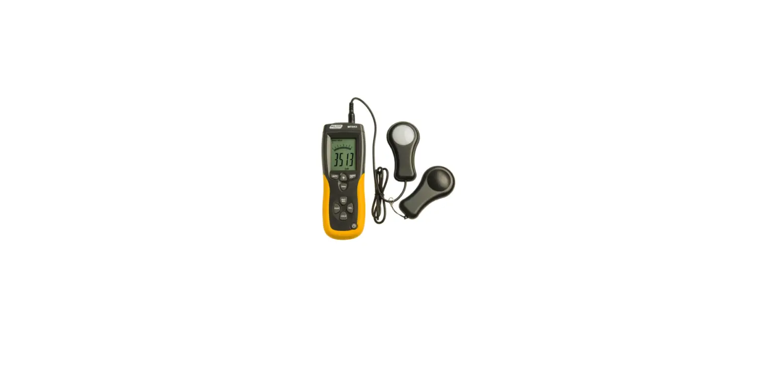
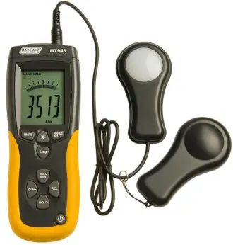
MAJOR TECH MT943 Data Logging Light Meter
INTRODUCTION
- The digital illuminance meter is a precision instrument used to measure illuminance (Lux, footcandle) in the field.
- It is meet CIE photopic spectral response.
- It is fully cosine corrected for the angular incidence of light.
- The illuminance meter is compact, tough and easy to handle owing to its construction.
- The light sensitive component used in the meter is a very stable, long-life silicon photo diode and spectral response filter.
SAFETY
- Light-measuring levels ranging form 0.1Lux~0.1kLux/0.01FC~0.01kFC, repeatedly.
- High accuracy and rapid response.
- Data-hold function for holding measuring values.
- Unit and sign display for easy reading.
- Automatic zeroing.
- Meter corrected for spectral relative efficiency.
- Correction factor need not be manually calculated for non-standard light sources.
- Short rise and fall times.
- Peak-hold function for tracing the peak signal of light pulse with least duration 10μs and keep it.
- Capable of selecting measuring mode in Lux or FC scale alternatively.
- Auto power off 15minutes or disable Auto Power Off.
- Maximum and minimum measurements.
- Relative reading .
- Easy to read large backlit display.
- USB output connect with PC.
- 4 Level ranging.
- 99 values in memory ,that could be read on the meter.
- More than 16000 values records datalogger.
SPECIFICATIONS
| Function Range | |
| Display | 3-3/4 digit LCD with high speed 40 segment bar graph. |
| Measuring Range | 400.0Lux, 4000Lux, 40.00kLux and 400.0kLux / 40.00FC, 400.0FC, 4000FC, 40.00kFC Note: 1FC=10.76Lux, 1kLux=1000Lux, 1kFC=1000FC |
| Over Range Display | LCD will show “OL” symbol. |
| Spectral Response | CIE Photopic (CIE human eye response curve). |
| Spectral Accuracy | CIE Vλ function f1’ ≤6% |
| Cosine Response | f2’ ≤2% |
| Accuracy | ±3% rdg±0.5%f.s. (<10,000Lux); ±4% |
| rdg±10d. (>10,000Lux) | |
| Repeatability | ±3% |
| Sampling Rate | 1.3 times/sec of analog bar-graph indication; 1.3times/sec of digital display. Datalogger sampling could be setup. |
| Photo Detector | One silicon photo diode and spectral response filter. |
| Operating Temperature | 0 to 40°C (32 to 104°F) |
| Operating Humidity | 0% to 80%RH |
| Storage Temperature | -10 to 50°C (14 to 140°F) |
| Storage Humidity | 0% to 70% RH |
| Power Source | 1 piece 9V battery |
| Photo Detector Lead Length | 150cm (approx.) |
| Photo Detector Dimensions | 115 x 60 x 20mm (L x W x H) |
| Meter Dimensions | 170 x 80 x 40mm (L x W x H) |
| Weight | 390g |
| Accessories | Carry Case, Instruction Manual, Battery |
DESCRIPTION
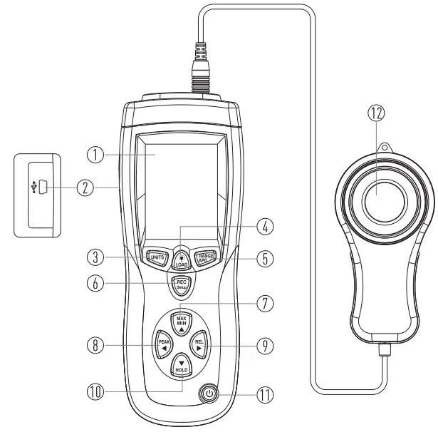
- LCD Display
- USB Interface
- UNITS Button
- Backlight/LOAD Control Button
- RANGE Button
- REC/SET Button
- MAX/MIN Button
- Peak Hold Button
- REL Button
- Data Hold Button
- Power Button
- Photo Detector
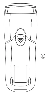
- Battery Cover
OPERATING INSTRUCTIONS
- Power-Up
- Press the Power Button to turn the meter ON or OFF.
Selecting the Lux or FC scale
- Set the RANGE Button to desired Lux or FC range.
Auto Power Off
- Press the REC/SET Button and RANGE/APO Button, enable the Auto
- Power Off or disable this function.
Over Range
- If the instrument only displays “OL”, the input signal is too strong, and a higher range should be selected.
- The range will show on the down of the LCD.
- LUX: 400->4k->40k->400k; FC: 40-> 400->4k->40k.
- 5.5. Data-Hold Mode
- Press the Data Hold Button to select Data-Hold mode.
- When Data-Hold mode is selected, the illuminance meter stops all further measurements.
- Press the Data Hold Button again to exit Data-Hold mode, then it resumes normal operation.
Peak-Hold Mode
- Press the Peak Hold Button to choose Pmax or Pmin recorder mode, and expose the photodetector to light pulse measuring field.
- Press the Peak Hold Button again to exit PEAK recorder mode, then the meter will resume normal operation.
Maximum and Minimum Mode
- Press the MAX/MIN Button to choose the Maximum (MAX) reading, Minimum (MIN) reading and current reading (MAX/MIN blink) recorder mode.
- Press the MAX/MIN Button again to exit this mode.
Relative Reading Mode
- Press the REL Button to enter Relative mode.
- The display shown zero value and the current reading will be stored as a zero-in value.
- Press the REL Button again to exit this mode.
USB Mode
- Connect with PC with USB, the “
 ” will displays in the screen.
Back-Light Function
- Press the Backlight Button to turn on; Press again to turn off.
Setup Time and Sampling Rate
- Press the MEM/SETUP Button and UNITS Button key to start to setup the time and sampling.
- The first setup target is the hour, press the PEAK or REL Button to choose the function of the setting
- Press the REL Button to choose function to repeat as below process: Hour->minter->second->sampling->month-> day->week->year- >hour……
- Press the PEAK Button to choose the function and repeat as below process: Hour->year->week->day->month-> sampling->second- >minter->hour->year……
- Press the MAX/MIN Button to add the function of setting, press the HOLD Button to reduce the function of setting.
- Hold the MEM/SETUP and UNITS Button to exit the setting time and sampling mode, and then confirm.
MEM Function
- Press the MEM/SET Button to save the present data.
- HOLD the LOAD Button for 5s to start to load the records.
- Press the MAX/MIN Button to add the number of records.
- Press the HOLD Button to reduce the number of records.
- After you do that you must hold the LOAD Button 5s to resume normal operation.
Datalogger Function
- Set up the time and sampling rate first, the default sampling rate is 1s.
- Hold the MEM/SETUP Button for 5s to start the datalogger function, the MEM on the screen will be flicker.
- If the memory IC is full,the memory number will show ‘OL’.
- Press the MEM/SETUP Button for 5s to stop the datalogger function, then the meter will resume normal operation.
- Then the datalogger number will return to 1, you could start your records again.
- HOLD the MEM/SETUP and LOAD Button for 5s to clear the 99 memory.
BATTERY CHECK-UP & REPLACEMENT
- If the battery power is not sufficient, LCD will display low battery and the replacement of one new battery is required.
- After turning off the meter, disconnect the battery cover with a screwdriver.
- Disconnect the battery from the instrument and replace it with a standard 9V battery and replace the cover
SPECTRAL SENSITIVITY CHARACTERISTIC
On the detector, the applied photodiode with filters makes the spectral sensitivity characteristic meeting C.I.E.(INTERNATIONAL COMMISSION ON ILLUMINATION) Photo curve V (λ ) as the following chart described.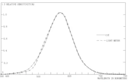
CONNECTING TO PC
System requirements
Windows 10 or higher.
Connection
- Switch the light meter on.
- Plug the other end of the connecting cable to the serial interface of the PC (USB).
- Plug the USB line connecting cable 13.6mm jack plug into the meter socket
- Start the light meter software.
- Selecting the COM port 3, note selects the 4 COM.
Note: You should switch the light meter on before you plug the USB line connecting cable 13.6mm jack plug into the meter.
INSTALLING THE SOFTWARE
- Start windows
- Insert the USB into the PC or Laptop and download the software.
- Now follow the installation program instructions.
- Once the software is installed, switch on the meter.
- Start the software.
- Selected the COM port 3, the note is 4.
- If the connection is not in order, the message “NO CONNECTION” appears on the screen.
MAINTENANCE
- The white plastic disc on the top of the detector should be cleaned with a damp cloth when necessary.
- Do not store the instrument where the temperature or humidity is excessively high.
- The reference level, as a marker on the face plate, is the tip of the photodetector globe.
- The calibration interval for the photodetector will vary according to operational conditions, but generally, the sensitivity decreases in direct proportion to the product of luminous intensity by the operational time.
- In order to maintain the basic accuracy of the instrument, periodic calibration is recommended.
RECOMMENDED ILLUMINATION
| Locations | Lux | FC | |
| Office | Conference, Reception Room | 200~750 | 18~70 |
| Clerical Work | 700~1,500 | 65~140 | |
| Typing Drafting | 1,000~2,000 | 93~186 | |
| Factory | Visual Work At Production Line | 300~750 | 28~70 |
| Inspection Work | 750~1,500 | 70~140 | |
| Electronic Parts Assembly Line | 1,500~3,000 | 140~279 | |
| Packing Work, Entrance Passage | 150~300 | 14~28 | |
| Hotel | Public Room, Cloakroom | 100~200 | 9~18 |
| Reception | 200~500 | 18~47 | |
| Cashier | 750~1,000 | 70~93 | |
| Store | Indoors Stairs Corridor | 150~200 | 14~18 |
| Show Window, Packing Table | 750~1,500 | 70~140 | |
| Forefront of Show Window | 1,500~3,000 | 140~279 | |
| Hospital | Sickroom, Warehouse | 100~200 | 9~18 |
| Medical Examination Room | 300~750 | 28~70 | |
| Operating Room, Emergency Treatment | 750~1,500 | 70~140 | |
| School | Auditorium, Indoor Gymnasium | 100~300 | 9~28 |
| Class Room | 200~750 | 18~70 | |
| Laboratory, Library, Drafting, Room | 500~1,500 | 47~140 | |
1FC=10.76Lux
South Africa
www.major-tech.com
[email protected]
Australia
www.majortech.com.au
[email protected]


