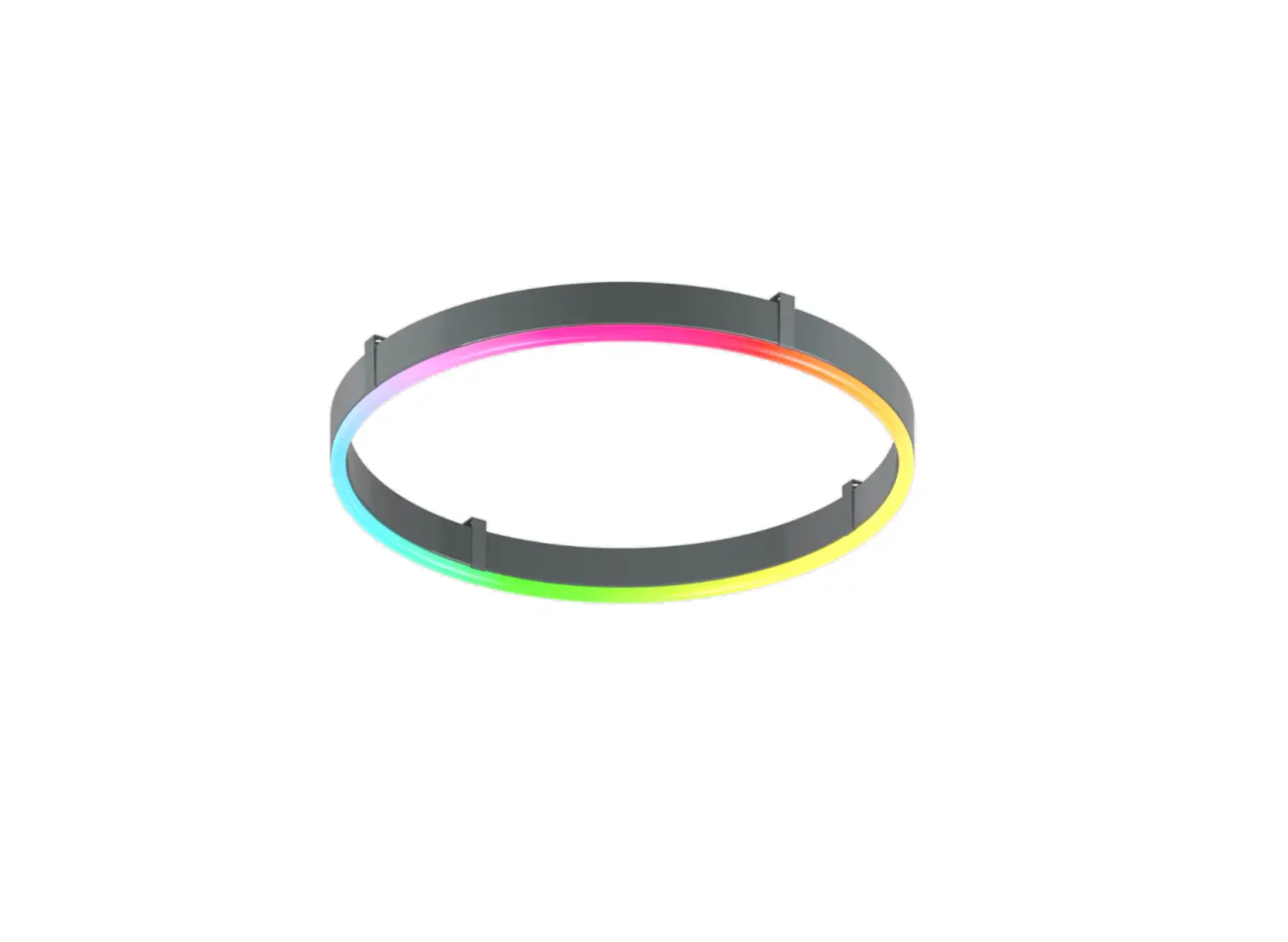
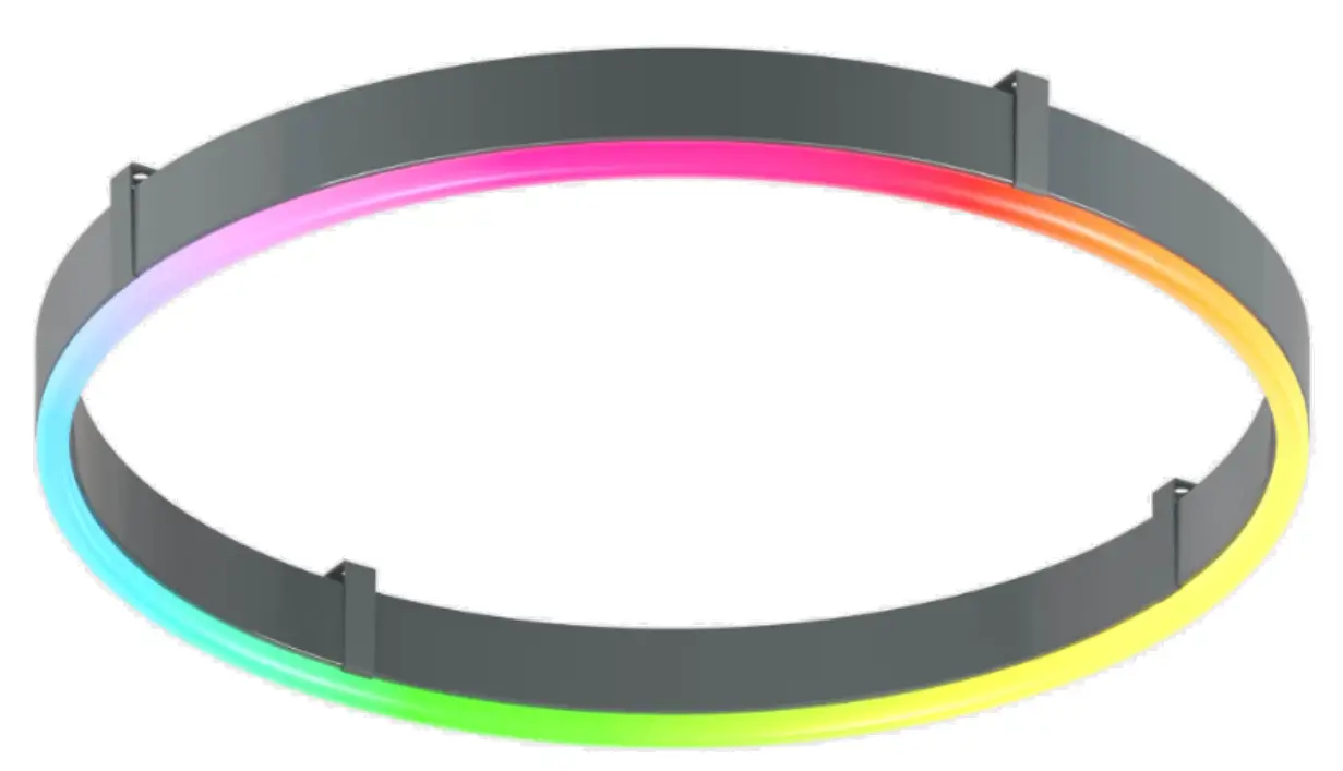
luminii Surface Dynamic Color Ring Surface Mount
Installation Instructions – Plexineon Surface Dynamic Color
Models: Plexineon Fixture Surface Mount Dynamic Color and Plexineon Rings Surface Mount Dynamic Color
Please read all instructions prior to installation and keep for future reference!
- . PRODUCT TO BE INSTALLED BY A QUALIFIED ELECTRICIAN.
- USE ONLY WITH CLASS 2 POWER UNIT
- 24 VOLTS DC
- SUITABLE FOR WET LOCATIONS
- . SURFACE MOUNT ONLY
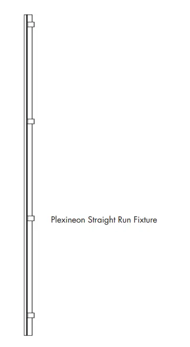 |  |
Straight run with mounting clips
| NOTE: Prior to installation all 24VDC wires must be present within 72” of the installation. Refer to the power supply installation instruction for additional information. NOTE: More than one person is recommended for this installation. |
1.1 Once the location or pattern is determined for Plexineon to be installed, start off by marking the area. Amount of mounting clips may vary dependent upon pattern. Reference diagrams below.
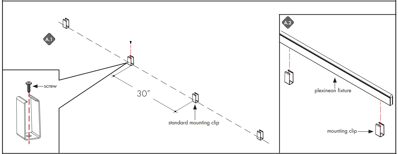
A.1 Line up and screw on the mounting clips to the mounting holes with no greater than 30” apart. Make sure it is straight by using a level.
A.2 Fix the plexineon fixture into installed mounting clips. See page 3 for clipping instructions.
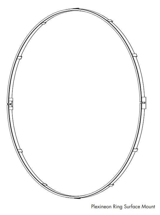
Curved run/rings with mounting clips
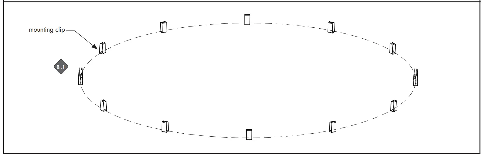
B.1 Determine the shape of the plexineon layout, then mark thel pattern onto the surface. Place the mounting clips with no greater than 30” apart. Screw onto surface.
B.2 Fix the plexineon bend/ring fixture into installed mounting clips. See page 3 for clipping instructions.
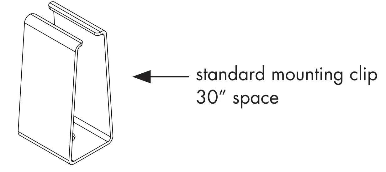
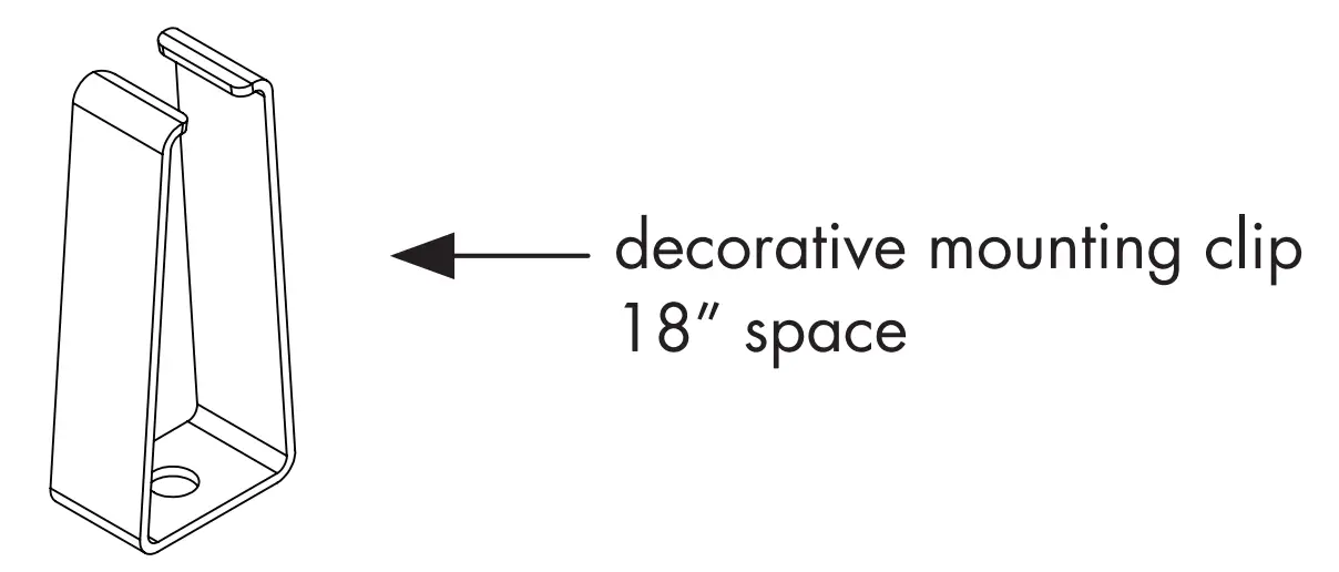
| NOTE: Standard Clips and Decorative Clips have different required spacing. |
 |  |
Install Fixtures into Mounting Clips
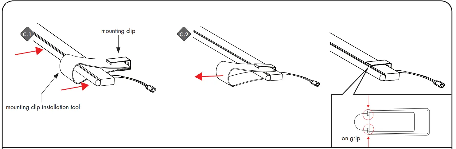
C.1 Make an U shape with mounting clip installation tool, insert two edges into mounting clip. Place plexineon fixture insde the shape. Then push the fixture into clip.
C.2 Remove the tool. Make sure mounting clip is clipped right on the grip.
RGB&RGBW WIRING DIAGRAM
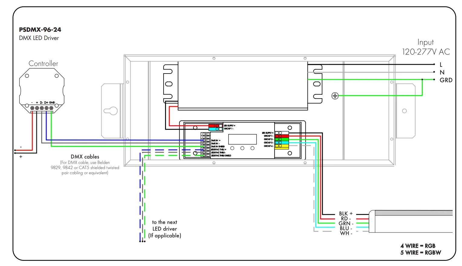
WIRING DIAGRAM
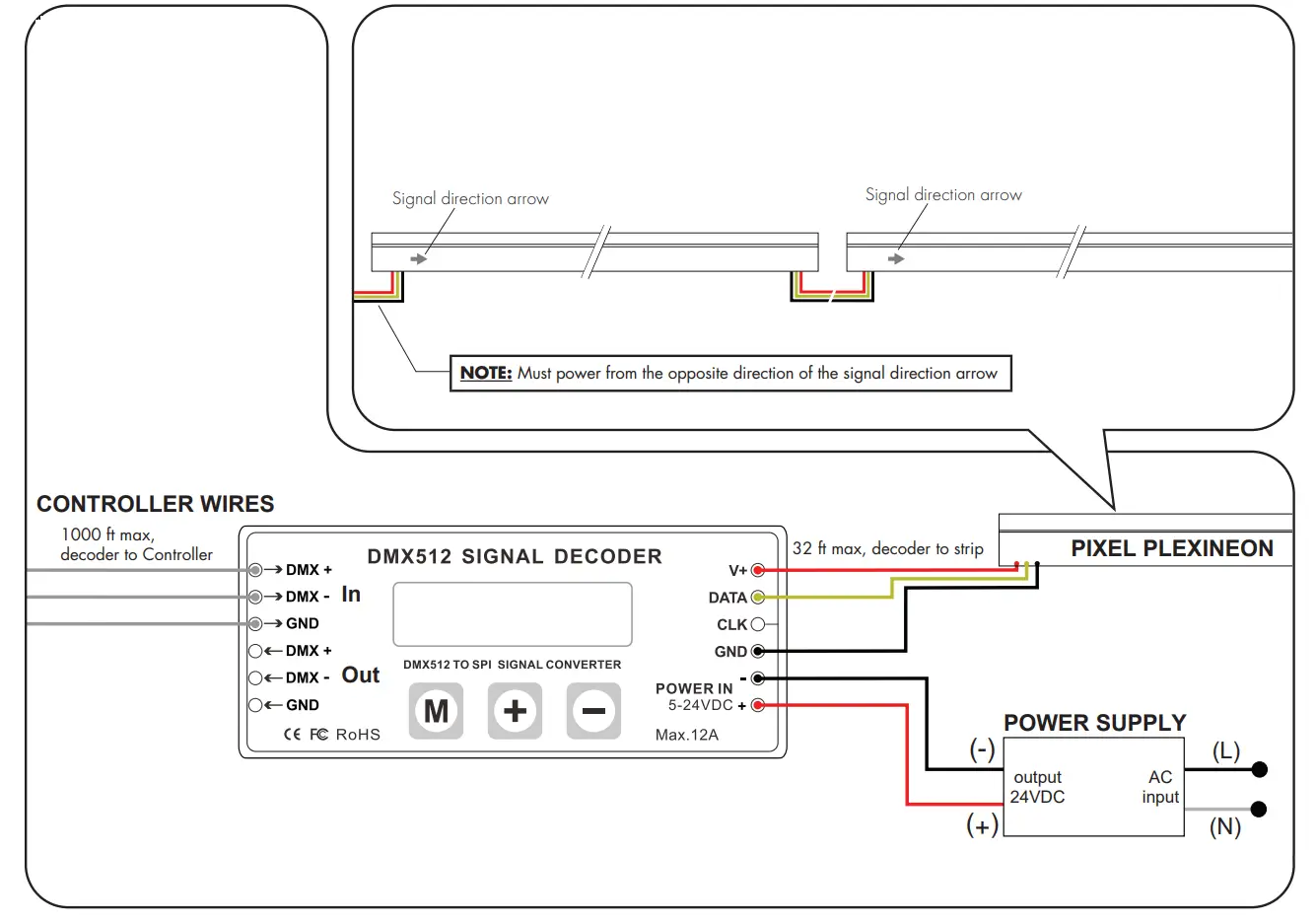
SR-DMX-SPI
Smart Pixel LineLED Decoder
| NOTE: Please make sure that power is turned off before wiring. Also, ensure that the correct power supply (voltage and wattage) is used to power the LED strips connected to the decoder. Follow illustrated wiring diagram. Use screwdriver to open and close connection slots. |
| NOTE: When connecting two or more LED strip lights or light fixtures, always make sure the signal direction arrows are pointing to same direction The signal direction arrow should appear on label of each section of LED fixture. |
OPERATING GUIDE
SR-DMX-SPI
Smart Pixel LineLED Decoder
There are three buttons on the decoder.
 | Parameter Setting |  | Increase Value |  | Decrease Value |
After operation, if no action was taken within 30s, the button lock, and backlight of the screen will turn off.
- Long press M button for 5s to unlock the buttons, and the backlight will turn on.
- Long press M button for 5s to switch between test mode and decode mode after unlocked.
During test mode, the first line of LCD will show: TEST MODE. Use test mode to verify RGBW Pixel functionality. Duirng decoder mode, the first line of LCD shows: DECODER MODE. Use decoder mode when connecting to a Controller and for final installation and customization.
The second line of the LCD Display shows the current setting and value. Note: 1 Pixel = 1 Cut Increment
| NOTE: When connected to a controller, DMX512 Signal Decoder will stay in “Decoder Mode”. |
MODE TABLE
| SETTING | LCD DISPLAY | VALUE RANGE | DESCRIPTION |
| Built-in Programs | TEST MODE MODE NO.: | 1-26 | See Program Table below |
| Program Speed | TEST MODE RUN SPEED: | 0-7 | 0: fast, 7: slow |
| DMX Address | DECODER MODE DMX ADDRESS: | 1-512 | Address of the starting point/Pixel of a program |
| DMX Signal RGB | DECODER MODE DMX RGB SEQ: | RGB, BGR, etc. | N/A |
| Pixel Quantity | DECODER MODE PIXEL QTY: | 1-170(RGB), 1-128(RGBW) | Number of Pixels to follow a program |
| IC TYPE | DECODER MODE IC TYPE: | 2903, 8903, 2904, 8904 | 2903: N/A, 2904: for RGBW, 8903: N/A, 8904: N/A |
| Color | DECODER MODE COLOR: | MONO, DUAL, RGB, RGBW | MONO: N/A, DUAL: N/A, RGB: N/A, RGBW: for RGBW |
| Pixel Merging / Pixel Size | DECODER MODE PIXEL MERGE: | 1-100 | Number of Pixels to merge together |
| RGB Sequence | DECODER MODE LED RGB SEQ: | RGBW, BGRW, etc. | Sequence of RGBW, 24 possible combinations |
| Integral Control | DECODER MODE ALL CONTROL: | YES, NO | Yes: Merge all Pixels No: Maintain individual Pixels or Merged Pixels |
| Reverse Control | DECODER MODE REV-CONTROL: | YES, NO | Reverse program order |
| Overall Brightness | DECODER MODE BRIGHTNESS: | 1-100 | 1: dimmest setting 100: brightest setting |
| NOTE: For Program Table Change: no fading/dimming between color changes Fade: fade/dim between color changes Chase: change pixel by pixel Chase with Trail: change pixel by pixel with fading between |
PROGRAM TABLE
| PROGRAM NO. | PROGRAM DESCRIPTION |
| 1 | Solid color: Red |
| 2 | Solid color: Green |
| 3 | Solid color: Blue |
| 4 | Solid color: Yellow |
| 5 | Solid color: Purple |
| 6 | Solid color: Cyan |
| 7 | Solid color: White |
| 8 | RGB change |
| 9 | Full color change |
| 10 | RGB fading |
| 11 | Full color fading |
| 12 | Red chase with trail |
| 13 | Green chase with trail |
| 14 | Blue chase with trail |
| 15 | White chase with trail |
| 16 | RGB chase with trail |
| 17 | Rainbow chase with trail |
| 18 | RGB chasing and fading |
| 19 | Red chasing green, chasing blue |
| 20 | Orange chasing purple, chasing cyan |
| 21 | Rainbow chase (7 colors) |
| 22 | Random twinkle: white over red |
| 23 | Random twinkle: white over green |
| 24 | Random twinkle: white over blue |
| 25 | White fading |
| 26 | Off |
*LUMINII RESERVES THE RIGHTS TO CHANGE SPECIFICATION & INSTRUCTION WITHOUT NOTICE

7777 Merrimac Ave
Niles, IL 60714
T 224.333.6033
F 224.757.7557
[email protected]
www.luminii.com