ARCOL FFLB Rack Mountable Resistive Load Banks
TECHNICAL DATA
GENERAL DATA
- Control/Auxiliary voltage : 230V AC or 115V AC (Based on Model Selected in Table-1)
- Control protection : Miniature Circuit Breaker (MCB)
- Over Temperature Protection : Thermal Switch
- Degree of protection : IP20
- Overall Dimensions :
Series W x D x H in mm FFLB1KW 482 x 375 x 179 FFLB3KW 482 x 375 x 311 FFLB5KW 482 x 375 x 356
LOAD DATA
| Model | Aux. Supply | Test Voltage | Power | Load Steps |
| FFLB1KW-110V AC | 230V AC | 110V AC | 1KW | 0.25KW x 4 |
| FFLB1KW-230V AC | 230V AC | 230V AC | 1KW | 0.25KW x 4 |
| FFLB3KW-110V AC | 230V AC | 110V AC | 3KW | 1KW x2; 0.5KW x1; 0.25KW x2 |
| FFLB3KW-230V AC | 230V AC | 230V AC | 3KW | 1KW x2; 0.5KW x1; 0.25KW x2 |
| FFLB5KW-110V AC | 230V AC | 110V AC | 5KW | 2KW x1; 1KW x2; 0.5KW x1; 0.25KW x2 |
| FFLB5KW-230V AC | 230V AC | 230V AC | 5KW | 2KW x1; 1KW x2; 0.5KW x1; 0.25KW x2 |
| FFLB1KW-110V AC_A | 115V AC | 110V AC | 1KW | 0.25KW x 4 |
| FFLB1KW-230V AC_A | 115V AC | 230V AC | 1KW | 0.25KW x 4 |
| FFLB3KW-110V AC_A | 115V AC | 110V AC | 3KW | 1KW x2; 0.5KW x1; 0.25KW x2 |
| FFLB3KW-230V AC_A | 115V AC | 230V AC | 3KW | 1KW x2; 0.5KW x1; 0.25KW x2 |
| FFLB5KW-110V AC_A | 115V AC | 110V AC | 5KW | 2KW x1; 1KW x2; 0.5KW x1; 0.25KW x2 |
| FFLB5KW-230V AC_A | 115V AC | 230V AC | 5KW | 2KW x1; 1KW x2; 0.5KW x1; 0.25KW x2 |
COMMISSIONING
HANDLING
Lifting handles can be used to move the equipment. Please ensure the equipment is handled carefully and that it is not dropped.
INSTALLATION
The fans on the front panel provides the forced cooling the unit needs to work efficiently. Hence care must be taken to ensure nothing blocks the fan and the air outlet. The unit is designed to provide a protection conforming to IP20 level and is intended for indoor use only.
CONNECTIONS
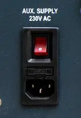
An auxiliary/control voltage is required for the operation of the fans, meters and some internal controls. A steady 230Vac 5A or 115Vac 5A (Based on Model Selected as per Table-1) source can be connected on the front panel marked Aux Supply with the cable provided.
SAFETY
- It is suggested that the unit is operated by a competent person who has received adequate training.
- Never connect or disconnect the load cables under testing. Perform a full shutting down of the load as per 3.3 before disconnection
- Never exceed the maximum test voltage of the unit.
- Extra care must be taken when relocating the load bank, dropping the unit could damage the functionality of the unit.
LOAD CONTROL
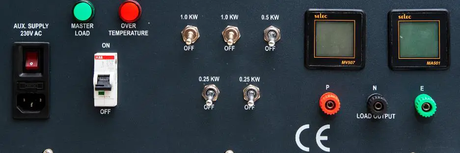
CONTROL PANEL – FFLB1KW
MASTER LOAD (Green Indicator): Indicates load is in ON condition and load step switches can be activated
OVER TEMPERATURE (Red Indicator): Indicates an over temperature in the unit.
CIRCUIT BREAKER: Protects the load unit from over current & short circuit.
STEP CONTROL SWITCHES (Toggle switches): The switches control the defined power steps. The total power
of the system will be the sum of the activated steps.
LOAD OUTPUT TERMINALS (P, N & E): The test source, Phase (P), Neutral (N) and Earth (E) should be connected to these terminals
VOLTAGE: These terminals are to be used if an external voltmeter is to be connected.
CURRENT: These terminals are to be used if an external ammeter is to be connected. The shorting link can be
removed before using an external ammeter. The link must be in place to function without an externally connected ammeter.
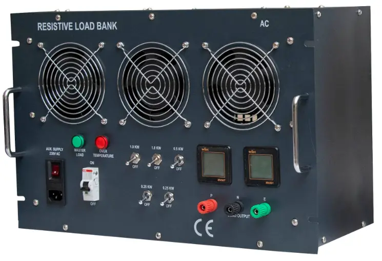
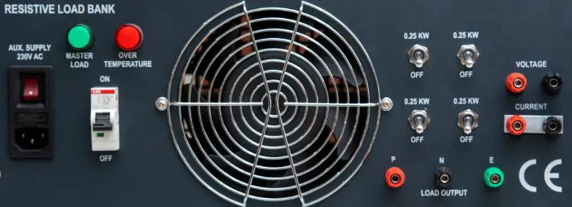
CONTROL PANEL – FFLB3KW & FFLB5KW
MASTER LOAD (Green Indicator): Indicates load is in ON condition and load step switches can be activated
OVER TEMPERATURE (Red Indicator): Indicates an over temperature in the Unit.
CIRCUIT BREAKER: Protects load unit from over current & short circuit.
STEP CONTROL SWITCHES (Toggle switches): The switches control the defined power steps. The total power of the system will be sum of the activated steps.
LOAD OUTPUT TERMINALS (P, N & E): The Phase (P), Neutral (N) and Earth (E) of the test source are to be connected to these terminals
DIGITAL METERS: Meters will show the voltage and current readings.
PROCESS FLOW
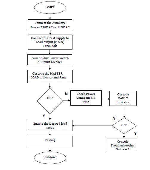
SHUTDOWN
- Turn off all the step control switches.
- Turn off the Circuit Breaker.
- Turn off the Auxiliary Supply.
Maintenance
GENERAL
- The unit is designed to have a maintenance free operation. Care to be taken that the air inlet and outlets are not blocked.
TROUBLESHOOTING
- No indicator is glowing:
- Auxiliary supply not connected or not available
- Failure of internal power supply
- Failure in control Circuit
- Fans are not running:
- Fuse may have blown out
- Failure in internal power supply
- Auxiliary Switch may have problem
- MASTER LOAD indicator is not glowing:
- Fuse may have blown out
- Indicator is damaged
- Step Control Switches are not working when it activated:
- Circuit breaker is not turned ON
- Thermal switch is not working
- Internal connection may have got disconnected
For any further queries & any information, please contact:
ARCOL UK Ltd
Unit 5, Threemilestone Industrial Estate
Threemilestone
Truro
Cornwall
TR4 9LG
U.K


